So far as I understood it, the triggering in a digital 'scope was just based on processing the data stream coming from the ADCs. This would mean that there is no trigger path available from before the channel coupling.
Checking this: my understanding wasn't correct. The triggering can still be performed in analogue terms, by taking the signal after the initial input gain (analogue). So the triggering selected may involve the sampled data, or it may not.
Presumably this is required if you want DC triggering on an AC coupled waveform.
If this wasn't done, then you would have to base the triggering on the sample data and so would not be able to implement a DC trigger level on AC coupled data (as you wouldn't know what the DC offset of the signal was). Unless there is some other process here that I am unaware of. 
(More stuff to figure out for a particular 'scope, I think. Certainly the way that trigger levels are reported back to the user varies, with Siglent not following the same convention that Tektronix does -- misleading me into assuming that this difference was a 'bug'.)
As you know but some peoples perhaps still do not know.
SDS1000X-E series (in outside China markets model SDS1202X-E) main channels trigger system is fully digital from ADC data stream as is example in R&S modern real time scopes.
In most older digital oscilloscopes there is analog side pathway after final amplifier before ADC for trigger circuits including trigger comparators.
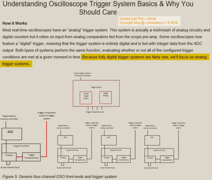
Conventional analog trigger system in some digital oscilloscopes.
In some cases traditional principle is possible to develop also very extremely good as example in some special Teledyne LeCroy models with clever trigger system.
Most simple analog pathway trigger system we can find in some older and/or bottom level digital oscilloscopes like example in Agilent, Tektronix older designs and/or bottom level models, Rigol 1000E, Siglent 1000CNL/CML/DL, Hantek.
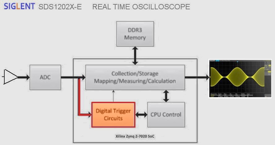
Siglent SDS1000X-E series RTO full digitall side trigger. Sidenote: Because there is one ADC chip internally interleaved for 1GSa/s for one channel mode it can not use for trig from unused main channel without reducing samplerate so there is not this function implemented.
Ext Trig do not have digital trigger system, it use conventional analog pathway with ltrigger comparator circuit. ExtTrig trigger have limited trigger functions and trigger timing quality overall is not at all in same level as trigger from main channel.
Trigger coupling AC (DC Block) 5.8Hz *
Trigger coupling LF reject (Also DC bloc and reduce < 2.08MHz * )
Trigger coupling HF reject (block or reduce > 1.27MHz * ) (also narrow trig hysteresis)
Trigger Noise reject off: normal trig hysteresis, on: wide trig hysteresis.
* limits from user manual version UM0101X-E02B


