-
Derek clearly talked about the earliest event and not what happened next, so I talked about it.QuoteFor the same reason: opening the valve emits a sound wave, because you're violently compressing/accelerating water.
The amount of energy is irrelevant. What you are not paying attention is that the energy that arrives first through space is not a spike of energy. It is a sustained continuous step and it does not disappear. When the rest of the energy flowing through space guided by the wires finally arrives, it is just added to the initial step.
Just as in the experiment proposed, it's a tiny amount of energy.
Comparing Derek's and Alpha Phoenix's setup, you'll see that the step "duration" is proportional to the length of the line. If it were 300km, it would "last" 1s. If it were infinite, it would last as much as you'd want. So, it is not a "transient", it is "standient", that doesn't go away.
If you want to know what happens next, it's in the line after:QuoteAlso there's a pressure wave propagating inside the pipe, much like there's a potential wave propagating along the wire (telegrapher's equations also work for the pipe).
It certainly deserves to be separated because the physical behavior is quite different: in the first part, you emit/receive radio waves, and it is why you get the d/c delay, but quickly decays; after, you have capacitive coupling, with a much higher power/duration and no radio waves emitted.
In both cases, you observe the exact same thing with pipes (given the impedance of air/metal/water, there's usually a very good shielding)Another problem is that some people who do not accept that the energy flows through space, are prepared to understand that the Poynting vector, perpendicular to the surface of the load, really conveys the energy that it will dissipate. But they don't understand that the wires are also resistors, and that the Poynting vector, perpendicular to whatever surface of the wire, be it radial or axial, will cause that energy to be dissipated by the wire.
Yes I can. Energy flows in wires and reappear in a lightbulb/engine/LED.
In other words, you cannot hand energy to a wire in one side and expect that this energy will reappear at the other side. The wire will dissipate it entirely.You can prove that by connecting any piece of wire to the poles of a battery. The energy will not be transferred from the negative pole to the positive pole. It'll simply be dissipated. Completely.
Yes energy is transferred from the battery to the short, through the wire.
Sounds ridiculous, but people do not connect the dots.
Saying it flows from the battery to the vacuum and then from the vacuum into the wire is not wrong, but it definitely sounds ridiculous. -
I promised an explanation of what happens in the waveform captured by Derek.
Nice.
Below with red is the voltage across the 1KOhm resistor with green is the supply voltage just after that R4 but it is an ideal voltage source so is basically the 20V supplied.
You can see that from simulation "LTspice" you get the same small power to resistor that is byproduct of charging the transmission line capacitance (I only simulated half the circuit as it is symmetrical).
Then at around 32ms current electron wave will travel half the line so at this time all line capacity is charged tho the part that charged first has already discharged not fully but significantly. Then as the electron travels on the other side of the transmission line the capacitance is being discharged starting with that far end continuing to maintain that limited amount of power for the lamp/resistor until about 65ns when the electron wave that left the source has finally arrived and rump up the lamp at full power (in fact slightly over as the remaining energy in capacitors is now basically fully discharged).
The inductors are also charged but at steady state they still contain significant amount of energy that will be delivered when switch is turned off.
(Attachment Link)
Below is the power graph (area under the graph represents energy).
Here you can see that significantly more power is provided by the source than what it ends up as heat on the lamp/resistor in the first 65ns and that difference is stored energy. The wires are much lower resistance so while there is some thermal energy wasted there it is insignificant compared to the 1K resistor.
(Attachment Link)
The full current bit is of course a no-brainer – ie the rise starting at 60.0/65.5 ns & finishing at 80.0 ns – plus the reflexion at 136.1 ns is standard stuff.
But i am very interested in the rise from 4.1 ns to 21.1/24.8 ns -- & the plateau of 3.7V at 24.8 ns, falling to 3.1V at 63.0/65.5 ns.
The 4.1 ns is only a ruff estimate, & it confirms Veritasium's claim of 3.3 ns (ie 1/c) from his first youtube gedanken.
So, can u get LTSpice to confirm the delay & rise & plateau in the first 65.5 ns?
In particular the weird angle of the initial rise from 4.1 ns to 21.1 ns.
AlphaPhoenix also got that there falling plateau in his AlphaPhoenix Xpt1 (pt2 yet to come)(if ever).
-
Nice.
The full current bit is of course a no-brainer – ie the rise starting at 60.0/65.5 ns & finishing at 80.0 ns – plus the reflexion at 136.1 ns is standard stuff.
But i am very interested in the rise from 4.1 ns to 21.1/24.8 ns -- & the plateau of 3.7V at 24.8 ns, falling to 3.1V at 63.0/65.5 ns.
The 4.1 ns is only a ruff estimate, & it confirms Veritasium's claim of 3.3 ns (ie 1/c) from his first youtube gedanken.
So, can u get LTSpice to confirm the delay & rise & plateau in the first 65.5 ns?
In particular the weird angle of the initial rise from 4.1 ns to 21.1 ns.
AlphaPhoenix also got that there falling plateau in his AlphaPhoenix Xpt1 (pt2 yet to come)(if ever).
You have a capacitor with air as dielectric and very long plates (the wires).
That initial rise in voltage is due to capacitance of the transmission line not being charged all at once as the line is long and the electron wave needs time to get from one side to the other.
The transmission line is simulated as multiple inductors and capacitors but they are ideal so it is consider the distance between plates is infinitely small so there no 3.3ns or so delay to correspond with the 1m distance between the plates (wires) in the real example.
That can be added to simulation but is not the relevant part. If you bring the wires closer you will get rid of those 3.3ns (reduce that time significantly) but the energy transfer will be done in the exact same way.
All energy travels trough wires and that initial energy is due to capacitive coupling so you are charging the capacitor (energy flows in the capacitor being stored there for later used and does not flow trough capacitor).
If that was the case then you will not need to close the switch to transfer energy as the switch is also a capacitor. -
If the gap is small then nonetheless the capacitor sits in the middle of a 1000 mm long short, & the speed of electricity is c/1 in the short, hence LTSpice should still give at least 3.3 ns.Nice.
You have a capacitor with air as dielectric and very long plates (the wires).
The full current bit is of course a no-brainer – ie the rise starting at 60.0/65.5 ns & finishing at 80.0 ns – plus the reflexion at 136.1 ns is standard stuff.
But i am very interested in the rise from 4.1 ns to 21.1/24.8 ns -- & the plateau of 3.7V at 24.8 ns, falling to 3.1V at 63.0/65.5 ns.
The 4.1 ns is only a ruff estimate, & it confirms Veritasium's claim of 3.3 ns (ie 1/c) from his first youtube gedanken.
So, can u get LTSpice to confirm the delay & rise & plateau in the first 65.5 ns?
In particular the weird angle of the initial rise from 4.1 ns to 21.1 ns.
AlphaPhoenix also got that there falling plateau in his AlphaPhoenix Xpt1 (pt2 yet to come)(if ever).
That initial rise in voltage is due to capacitance of the transmission line not being charged all at once as the line is long and the electron wave needs time to get from one side to the other.
The transmission line is simulated as multiple inductors and capacitors but they are ideal so it is consider the distance between plates is infinitely small so there no 3.3ns or so delay to correspond with the 1m distance between the plates (wires) in the real example.
That can be added to simulation but is not the relevant part. If you bring the wires closer you will get rid of those 3.3ns (reduce that time significantly) but the energy transfer will be done in the exact same way.
All energy travels trough wires and that initial energy is due to capacitive coupling so you are charging the capacitor (energy flows in the capacitor being stored there for later used and does not flow trough capacitor).
If that was the case then you will not need to close the switch to transfer energy as the switch is also a capacitor.
And, if modelled correctly, LTSpice should give the funny rise & the funny falling plateau.
Re the switch, this might be a capacitor, but before it is closed the circuit is in steady state. -
If the gap is small then nonetheless the capacitor sits in the middle of a 1000 mm long short, & the speed of electricity is c/1 in the short, hence LTSpice should still give at least 3.3 ns.
And, if modelled correctly, LTSpice should give the funny rise & the funny falling plateau.
Re the switch, this might be a capacitor, but before it is closed the circuit is in steady state.
A capacitor with a 1000mm gap between plates will require 3.3ns and one with 1mm gap will require 3.3ps
LTspice as far as I know has no option to specify the gap between plates and all comercial capacitors even the very high voltage ones will typically have much less than 1mm gap as the smaller the gap the larger the capacity.
So there is nothing strange or not understood about that 3.3ns.
When you close the switch exactly at that contact interface one electron will move from one side of the switch to the other and if a capacitor is in series in the loop as is the case in Derek's experiment then it takes 3.3ns for an electron on the other side of the 1m thick dielectric (air) to feel the effect and vacate a space.
In the battery the space is much smaller so when switch is closed and one electron moves on the other side of the switch the electron wave will travel in to battery say maybe 100mm from the switch then inside the battery the gap say is 1mm and so that electron that left from battery to switch will cause an electron from the wire connected on the other side of the battery to be accepted in the battery and so if total distance is 101mm in a straight line it may take as little as 0.33ns but likely it can not capacitively couple in straight line so it will be an ark maybe say 150mm so around 0.50ns then both sides are coupled at the same time with the wire above that is at about 1m thus 3.3nm + 0.5ns will be the total time from closing the switch until the first packet of energy is transferred from battery to the capacitor (transmission line is a capacitor) and since the lamp is in series between this two 1m capacitors all current used to charge the capacitor also will go through the lamp and be lost as heat and maybe photos. -
Surely LTSpice is told the distance tween wires, ie 1000 mm. And the small gap tween plates can be ignored.If the gap is small then nonetheless the capacitor sits in the middle of a 1000 mm long short, & the speed of electricity is c/1 in the short, hence LTSpice should still give at least 3.3 ns.
A capacitor with a 1000mm gap between plates will require 3.3ns and one with 1mm gap will require 3.3ps
And, if modelled correctly, LTSpice should give the funny rise & the funny falling plateau.
Re the switch, this might be a capacitor, but before it is closed the circuit is in steady state.
LTspice as far as I know has no option to specify the gap between plates and all comercial capacitors even the very high voltage ones will typically have much less than 1mm gap as the smaller the gap the larger the capacity.
So there is nothing strange or not understood about that 3.3ns.
When you close the switch exactly at that contact interface one electron will move from one side of the switch to the other and if a capacitor is in series in the loop as is the case in Derek's experiment then it takes 3.3ns for an electron on the other side of the 1m thick dielectric (air) to feel the effect and vacate a space.
In the battery the space is much smaller so when switch is closed and one electron moves on the other side of the switch the electron wave will travel in to battery say maybe 100mm from the switch then inside the battery the gap say is 1mm and so that electron that left from battery to switch will cause an electron from the wire connected on the other side of the battery to be accepted in the battery and so if total distance is 101mm in a straight line it may take as little as 0.33ns but likely it can not capacitively couple in straight line so it will be an ark maybe say 150mm so around 0.50ns then both sides are coupled at the same time with the wire above that is at about 1m thus 3.3nm + 0.5ns will be the total time from closing the switch until the first packet of energy is transferred from battery to the capacitor (transmission line is a capacitor) and since the lamp is in series between this two 1m capacitors all current used to charge the capacitor also will go through the lamp and be lost as heat and maybe photos.
In which case LTSpice should be able to model the initial transient delay & rise & plateau. -
Surely LTSpice is told the distance tween wires, ie 1000 mm. And the small gap tween plates can be ignored.If the gap is small then nonetheless the capacitor sits in the middle of a 1000 mm long short, & the speed of electricity is c/1 in the short, hence LTSpice should still give at least 3.3 ns.
A capacitor with a 1000mm gap between plates will require 3.3ns and one with 1mm gap will require 3.3ps
And, if modelled correctly, LTSpice should give the funny rise & the funny falling plateau.
Re the switch, this might be a capacitor, but before it is closed the circuit is in steady state.
LTspice as far as I know has no option to specify the gap between plates and all comercial capacitors even the very high voltage ones will typically have much less than 1mm gap as the smaller the gap the larger the capacity.
So there is nothing strange or not understood about that 3.3ns.
When you close the switch exactly at that contact interface one electron will move from one side of the switch to the other and if a capacitor is in series in the loop as is the case in Derek's experiment then it takes 3.3ns for an electron on the other side of the 1m thick dielectric (air) to feel the effect and vacate a space.
In the battery the space is much smaller so when switch is closed and one electron moves on the other side of the switch the electron wave will travel in to battery say maybe 100mm from the switch then inside the battery the gap say is 1mm and so that electron that left from battery to switch will cause an electron from the wire connected on the other side of the battery to be accepted in the battery and so if total distance is 101mm in a straight line it may take as little as 0.33ns but likely it can not capacitively couple in straight line so it will be an ark maybe say 150mm so around 0.50ns then both sides are coupled at the same time with the wire above that is at about 1m thus 3.3nm + 0.5ns will be the total time from closing the switch until the first packet of energy is transferred from battery to the capacitor (transmission line is a capacitor) and since the lamp is in series between this two 1m capacitors all current used to charge the capacitor also will go through the lamp and be lost as heat and maybe photos.
In which case LTSpice should be able to model the initial transient delay & rise & plateau.
Spice is not the sort of simulation you are imagining. The transmission line is done by adding a bunch of inductors and capacitors together to simulate those two wires.
And as mentioned that 3.3 or so ns delay at the beginning is irrelevant. I can add that delay but it will make no difference.
What you need to understand is that two parallel wires are a capacitor thus an energy storage device.
If you leave the ends open (the 1m pipes that connects the two parallel 10m pipes) the you will still have this first 65ns current through the lamp/resistor as the capacitor's one on each side will be charged but once they are charged you no longer have any current unless you reverse the battery polarity so that you discharge those capacitors and charge them in the other direction then it will again stop.
So energy flows in and out of capacitors and not through capacitors. Energy flows in to capacitor is the key as that energy is not doing work it is stored and just because wires have resistance and a lamp is in series it means that charging is not efficient so not all energy from the source will end up in capacitor as some will be lost to power the lamp/heat the resistor. -
Now let's consider the analogy of a spaceship returning to earth. It has both kinetic energy and gravitational potential energy. Both are converted to thermal energy as it reenters the atmosphere. So what carries the gravitational potential energy? Is it the spaceship or the Earth's gravitational field?
Gravitational potential energy is the additional energy the spaceship would gain if it were to travel a path between the two points used as the references.
It is not 'carried', it is transferred from the field as it makes the journey though the field. -
Now let's consider the analogy of a spaceship returning to earth. It has both kinetic energy and gravitational potential energy. Both are converted to thermal energy as it reenters the atmosphere. So what carries the gravitational potential energy? Is it the spaceship or the Earth's gravitational field?
Gravitational potential energy is the additional energy the spaceship would gain if it were to travel a path between the two points used as the references.
It is not 'carried', it is transferred from the field as it makes the journey though the field.
This seems to be getting out of subject but here is an explanation:
Have you seen the Einstein's explanation of gravity ?
It shows a straight fabric and when an object with mass is added it creates a valley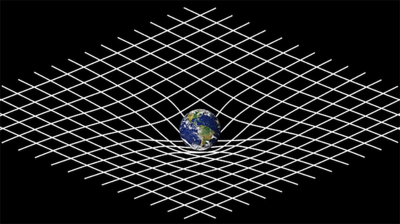
Now any other object with mass near the planet like the spaceship will also bend that fabric based on spaceship weight thus both planet and spaceship will slide closer to each other.
If there is no mass there is no gravitational field and similarly if there is no electron imbalance there is no electric field.
-
This picture is widely understood to be an analogy. It does not represent what really happens, it is only a pictorial simplification.
The complication here is that general relativity indicates that you can have gravity without mass, and an internal observer experiencing such gravity cannot tell whether the experienced gravitational field is due to mass or otherwise. -
I agree that the 1000 mm end connection is irrelevant to the initial transients.
Spice is not the sort of simulation you are imagining. The transmission line is done by adding a bunch of inductors and capacitors together to simulate those two wires.
Surely LTSpice is told the distance tween wires, ie 1000 mm. And the small gap tween plates can be ignored.If the gap is small then nonetheless the capacitor sits in the middle of a 1000 mm long short, & the speed of electricity is c/1 in the short, hence LTSpice should still give at least 3.3 ns.
A capacitor with a 1000mm gap between plates will require 3.3ns and one with 1mm gap will require 3.3ps
And, if modelled correctly, LTSpice should give the funny rise & the funny falling plateau.
Re the switch, this might be a capacitor, but before it is closed the circuit is in steady state.
LTspice as far as I know has no option to specify the gap between plates and all comercial capacitors even the very high voltage ones will typically have much less than 1mm gap as the smaller the gap the larger the capacity.
So there is nothing strange or not understood about that 3.3ns.
When you close the switch exactly at that contact interface one electron will move from one side of the switch to the other and if a capacitor is in series in the loop as is the case in Derek's experiment then it takes 3.3ns for an electron on the other side of the 1m thick dielectric (air) to feel the effect and vacate a space.
In the battery the space is much smaller so when switch is closed and one electron moves on the other side of the switch the electron wave will travel in to battery say maybe 100mm from the switch then inside the battery the gap say is 1mm and so that electron that left from battery to switch will cause an electron from the wire connected on the other side of the battery to be accepted in the battery and so if total distance is 101mm in a straight line it may take as little as 0.33ns but likely it can not capacitively couple in straight line so it will be an ark maybe say 150mm so around 0.50ns then both sides are coupled at the same time with the wire above that is at about 1m thus 3.3nm + 0.5ns will be the total time from closing the switch until the first packet of energy is transferred from battery to the capacitor (transmission line is a capacitor) and since the lamp is in series between this two 1m capacitors all current used to charge the capacitor also will go through the lamp and be lost as heat and maybe photos.
In which case LTSpice should be able to model the initial transient delay & rise & plateau.
And as mentioned that 3.3 or so ns delay at the beginning is irrelevant. I can add that delay but it will make no difference.
What you need to understand is that two parallel wires are a capacitor thus an energy storage device.
If you leave the ends open (the 1m pipes that connects the two parallel 10m pipes) the you will still have this first 65ns current through the lamp/resistor as the capacitor's one on each side will be charged but once they are charged you no longer have any current unless you reverse the battery polarity so that you discharge those capacitors and charge them in the other direction then it will again stop.
So energy flows in and out of capacitors and not through capacitors. Energy flows in to capacitor is the key as that energy is not doing work it is stored and just because wires have resistance and a lamp is in series it means that charging is not efficient so not all energy from the source will end up in capacitor as some will be lost to power the lamp/heat the resistor.
And i agree that parallel wires are a capacitor.
Old electricity i think says that electrons passing the switch will repel electrons from the other wire. Some of these will go left (towards the bulb) & some will go right.
Hence electrons will start to pass through the bulb at 3.3 ns.
The rise ends at 21.1/24.8 ns. This means that the electron wavefront passing the switch has propagated say 7.3 m at 3.3 ns/m
That propagation includes say 1 m crossing tween the wires, which leaves 6.3 m in the wires.
That 6.3 m is say 3.2 m along the primary wire, plus 3.1 m to the bulb along the secondary wire.
Hence the plateauing started when the wavefront was 3.2 m along past the switch. This is 1/3rd of the way to the end of that 10 m stretch of wire/tube.
At 24 ns the induction process of squeezing of electrons from the secondary wire reaches a peak value of 3.7V, after which the voltage across the bulb drops from 3.7v to 3.1V.
I think that the same kind of rise & plateau can be seen in the AlphaPhoenix-X.
I had a look. Brian's rise takes about 75 ns, for a gap of say 250 mm, ie ¼ of Veritasium's gap of 1000 mm.
AlphaPhoenix's L was say 250 m, & Veritasium's L was say 10 m.
AlphaPhoenix's plateaux went up not down, ie it went from say 1.8V up to 2.2V at say 1600 ns.
AlphaPhoenix's 75 ns indicates that the end of his rise was when the wavefront was 11.2 m past the switch.
Add 1 ns for the 250 mm gap, plus 11.2 m going back to the bulb, & we have our 75 ns.
I suspect that the height of the wires & tubes above the dirt would affect the rises etc.
Anyhow, any lumped element transmission line model worth its salt will surely give these kinds of numbers.
-
This picture is widely understood to be an analogy. It does not represent what really happens, it is only a pictorial simplification.
The complication here is that general relativity indicates that you can have gravity without mass, and an internal observer experiencing such gravity cannot tell whether the experienced gravitational field is due to mass or otherwise.
As any analogy it has limitations.
The fact remains that energy cannot be transferred by the electric field else capacitors will not exist.
It all reducess to whatever you think energy flows through a capacitor (demonstrably untrue) or flows in and out of a capacitor.
All you need to check this is take a battery a lamp and a capacitor and connect all of them in series. Depending how large is the capacitor (in therms of energy storage capacity) you may see the lamp light up as energy is transferred from the battery to the capacitor to be charged but once the capacitor is at same potential as the battery meaning it can not accept any more energy the current flow will stop and so no energy transfer.
Then by removing the battery and only connecting the lamp and capacitor in a loop the energy that was stored can be recovered and lamp will be illuminated for the same amount of time as it was when capacitor was charged. -
It all reducess to whatever you think energy flows through a capacitor (demonstrably untrue) or flows in and out of a capacitor.
Oh? What will you say about that?QuoteAll you need to check this is take a battery a lamp and a capacitor and connect all of them in series. Depending how large is the capacitor (in therms of energy storage capacity) you may see the lamp light up as energy is transferred from the battery to the capacitor to be charged but once the capacitor is at same potential as the battery meaning it can not accept any more energy the current flow will stop and so no energy transfer.
Then by removing the battery and only connecting the lamp and capacitor in a loop the energy that was stored can be recovered and lamp will be illuminated for the same amount of time as it was when capacitor was charged.
Congratulations. You just demonstrated that energy flows through the capacitor. -
The fact remains that energy cannot be transferred by the electric field else capacitors will not exist.
It all reducess to whatever you think energy flows through a capacitor (demonstrably untrue) or flows in and out of a capacitor.
All you need to check this is take a battery a lamp and a capacitor and connect all of them in series. Depending how large is the capacitor (in therms of energy storage capacity) you may see the lamp light up as energy is transferred from the battery to the capacitor to be charged but once the capacitor is at same potential as the battery meaning it can not accept any more energy the current flow will stop and so no energy transfer.
Then by removing the battery and only connecting the lamp and capacitor in a loop the energy that was stored can be recovered and lamp will be illuminated for the same amount of time as it was when capacitor was charged.
Are you saying that if you have a lamp between two capacitors (so all three components are in series) that it is impossible to get the lamp to glow?
Because that would be "energy passing through the capacitors" to me. If not, where did the energy that makes the lamp glow come from?
-
Congratulations. You just demonstrated that energy flows through the capacitor.
You will need to understand what energy and energy storage is to make that claim. -
Are you saying that if you have a lamp between two capacitors (so all three components are in series) that it is impossible to get the lamp to glow?
Because that would be "energy passing through the capacitors" to me. If not, where did the energy that makes the lamp glow come from?
I was mentioning a battery but yes if one of the capacitors is charged then yes.
It will only glow for a few moments and stop as soon as the two capacitors become equally charged. There is still energy to make the lamp glow in the two capacitors but they can not do that as energy will not flow through them.
There is no current flow through a dielectric (if there is then something is wrong and that is no longer a dielectric). -
Are you saying that if you have a lamp between two capacitors (so all three components are in series) that it is impossible to get the lamp to glow?
Because that would be "energy passing through the capacitors" to me. If not, where did the energy that makes the lamp glow come from?
I was mentioning a battery but yes if one of the capacitors is charged then yes.
It will only glow for a few moments and stop as soon as the two capacitors become equally charged. There is still energy to make the lamp glow in the two capacitors but they can not do that as energy will not flow through them.
There is no current flow through a dielectric (if there is then something is wrong and that is no longer a dielectric).
I've put a pair of LEDs between two caps, with a current limiting resistor. Where is the energy coming from that is making these LED glow?
I've used 2 LEDs so you can be sure that I am not playing any funny games with AC. One glows when DC voltage is applied, the other when the caps are discharged after DC is removed.
I can repeat the cycle over and over, so more energy is getting to the LEDs somehow, and charges are moving through the LEDs... but you say this energy is not going through the capacitors? -
It certainly deserves to be separated because the physical behavior is quite different:
Separated.
Since the 19th century, everybody thought that everything electric and magnetic, from DC to cosmic rays, through radio waves, heat, light, ultraviolet, X-rays and whatnot, is the manifestation of the same freaking physical phenomenon.
Now you're saying that they are different. I wonder why the Nobel Committee has not noticed you yet.QuoteYes I can. Energy flows in wires and reappear in a lightbulb/engine/LED.
QuoteYes energy is transferred from the battery to the short, through the wire.
If you say so, it must be true.
-
Considering capacitors is sure interesting, considering inductive coupling as well.
We know we can transfer energy without "wires". That's for sure. But what would the fundamental difference be? If there is any? -
I've put a pair of LEDs between two caps, with a current limiting resistor. Where is the energy coming from that is making these LED glow?
I've used 2 LEDs so you can be sure that I am not playing any funny games with AC. One glows when DC voltage is applied, the other when the caps are discharged after DC is removed.
I can repeat the cycle over and over, so more energy is getting to the LEDs somehow, and charges are moving through the LEDs... but you say this energy is not going through the capacitors?
Use a battery. You have a low quality power supply that has a lot of ripple thus your capacitors are charged and discharged continuously.
Is basically an AC supply with a DC offset. -
I am not sure about the gist of this argument, but, radio waves are not photons, & photons are not radio waves.It certainly deserves to be separated because the physical behavior is quite different:
Separated.
Since the 19th century, everybody thought that everything electric and magnetic, from DC to cosmic rays, through radio waves, heat, light, ultraviolet, X-rays and whatnot, is the manifestation of the same freaking physical phenomenon.
Now you're saying that they are different. I wonder why the Nobel Committee has not noticed you yet.QuoteYes I can. Energy flows in wires and reappear in a lightbulb/engine/LED.
QuoteYes energy is transferred from the battery to the short, through the wire.
If you say so, it must be true.
Radio waves are em radiation.
Photons are photons, they emit em radiation. -
I've put a pair of LEDs between two caps, with a current limiting resistor. Where is the energy coming from that is making these LED glow?
I've used 2 LEDs so you can be sure that I am not playing any funny games with AC. One glows when DC voltage is applied, the other when the caps are discharged after DC is removed.
I can repeat the cycle over and over, so more energy is getting to the LEDs somehow, and charges are moving through the LEDs... but you say this energy is not going through the capacitors?
Use a battery. You have a low quality power supply that has a lot of ripple thus your capacitors are charged and discharged continuously.
Is basically an AC supply with a DC offset.
My admittedly low quality PSU, replaced with a 9V battery. Same result.
Also if it was an AC supply, both LEDs would glow. -
My admittedly low quality PSU, replaced with a 9V battery. Same result.
Also if it was an AC supply, both LEDs would glow.
Not sure what you are doing there. Where is the black cable connected ? I see just what looks like a red banana plug that you touch on either positive or negative of a 9V battery. -
My admittedly low quality PSU, replaced with a 9V battery. Same result.
Also if it was an AC supply, both LEDs would glow.
Not sure what you are doing there. Where is the black cable connected ? I see just what looks like a red banana plug that you touch on either positive or negative of a 9V battery.
Black cable is held against the negative of the 9V battery. -
Black cable is held against the negative of the 9V battery.
I see so you where charging and discharging the capacitors. LED's can glow at a few uA so it will take quite some time for them to dim as capacitors charge and those capacitors may have leakage current in that region.
I just tested with a large 4700uF 35Vdc new capacitor and my small white LED had a small glow even after 30 to 50 seconds (did not count) the same level of glow it has if it conducts through my finger so I suspect a few nA
I never used electrolytic capacitors in any of my projects and did a quick search and it seems they do have some leakage current due to the type of electrolyte they use. Water based ones have the largest leakage but all have even a few uA much more than nA modern LED's can glow at.
So I learned something new and that is that electrolytics are not just capacitors but also a parallel resistor.
There are good reason I never consider electrolytics for my projects (I do not like things with finite life).
Edit: This is the exact one that I just used https://www.mouser.ca/ProductDetail/United-Chemi-Con/EGPA350ELL472MM40S?qs=beQ1fBGcmj2M%2Fui1vdONPg%3D%3D
Looking at the spec it has 4uA of leakage current so fairly significant and this is not a non brand and purchased from mouser.
Is just there on first page and that 4uA is best case can bemore https://www.mouser.ca/datasheet/2/420/GPALL_e-2509122.pdf
In my particular case should be about 705uA based on use case 8V battery 3V on LED so 5V on the capacitor 5V * 4700uF * 0.03 but mine was no where near close to that probably is worse case and was more like 10uA max based on almost invisible glow.