Received mine today as hoped.
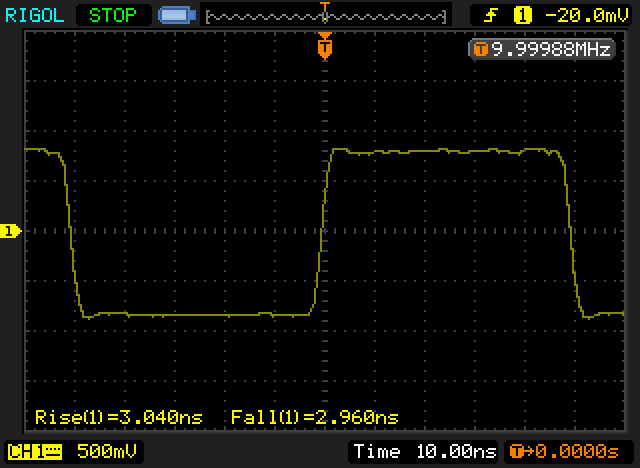
Tested on Rigol MSO2302A (300MHz, upgraded...) and Tektronix 2445A (150 MHz). Results as awaited, perfect!
The software rose an error when launched: Error '13' uncompatible type (Windows 10).
Cheers,
I am looking into the problem - looks like a decimal comma/point issue.
Leo
Hi Leo,
Works perfectly well now, including calibration. Thanks a lot

I have modified the configuration software to fix the decimal comma/point issue for locales that use decimal comma.
You should tell Rigol how to do that...
They say it's impossible to fix
their PSU control software.
we can't change it. All of our test devices needs point separator for communication
I tested a few Rigol scopes with the pulse generator.
DS1102E

DS1074Z 100 MHz


DS2072 300 MHz with 1M input


DS2072 with 50R through terminator


DS4014 500 MHz


One thing that could be noticed when testing several Rigol scopes one after another was that as the series number gets higher the user experience can be quite different and feels much snappier. Well the hardware under the hood is quite different too.
And then a few other scopes too
Keysight DSOX3014T


LeCroy WavePro 7300A


I think it would be nice to collect the results into an online spreadsheet and a chart similar to this one - any volunteers

with an estimated Tpulser ~50ps the rise-times should be accurate to 10% up to 3 or 3.5 GHz - if my chart is roughly right..
I just started a Google spreadsheet and added what's been posted in this thread so far. See attached screenshot.
Any suggested changes before I try to make it public (never made a shared one before)? What should we call it?
I just started a Google spreadsheet and added what's been posted in this thread so far. See attached screenshot.
Any suggested changes before I try to make it public (never made a shared one before)? What should we call it?
I'd make the default sort order manufacturer and then model.
I just started a Google spreadsheet and added what's been posted in this thread so far. See attached screenshot.
Any suggested changes before I try to make it public (never made a shared one before)? What should we call it?
awesome
I'd make the X-axis the manufacturer specified BW of the scope.
maybe there's a way to make a shaded background between say 0.35/BW and 0.45/BW - where we'd expect the measurements to fall.
Here are some of my scopes:
Tek 2246 100MHz Analog 50 ohm* 2070 2280
Tek 2465 300MHz Analog 50 ohm 1080 1260
Tek 7904/7A26 200MHz Analog 50 ohm* 1650 1700
Tek 7904/7A24 400MHz Analog 50 ohm 700 800
Rigol 1074Z 70MHz 1GS/sec 50 ohm* 3940 4570
Rigol 1074Z 20MHz 1GS/sec 50 ohm* 14630 15910 (20MHz bandwidth limit)
Siglent SDS1202X 200MHz 1GS/sec 50 ohm 1750 1790
OWon PDS8102T 100MHz 1GS/sec 50 ohm* 2040 1960
*= 1Meg input with external 50 ohm pass through terminator
Any suggested changes before I try to make it public (never made a shared one before)? What should we call it?
Yes, add a column with Leo's calculation for the scope's rise time
see below..
Now my last scope for this test, a Keysight MSO-X-6004A, 6 GHz, 50 Ohm
Rise time is 88 ps
Assuming total system risetime Tsystem2 = Tscope2 + Tpulser2
It checks out reasonably well:
Tsystem = 88ps, Tpulser = 50ps
From there Tscope = 72ps
MSO-X-6004A specification lists 75ps risetime.
Pleasant UI on that Fluke.
Good idea for the spreadsheet and good suggestions to improve.
Two remarks for my lines :
- first scope is in fact Rigol MSO2072A upgraded in MSO2302A (that's what appears in the system info after upgrade)
- second one is Tek 2445A, not 2445
Gixy
Hi,
I've fixed the mistakes pointed out by Gixy, added the datapoints provided by Tom45 and added a column with the calculated scope risetime taking the risetime of the pulser into consideration. The calculated bandwidth numbers are then based on the calculated risetime.
I've opened the spreadsheet up for viewing (at least I think I have):
https://docs.google.com/spreadsheets/d/1uknvUdL4gNuTyuK7MNAkCj95GFSsDtfgr7nObVppFiE/edit?usp=sharingI've yet to figure out the sorting stuff and I don't quite understand what graphing we should do. If anyone wants to help out just drop me a PM and I'll try to set you up with editing rights (or should I just allow full editing rights?)
MDO3054 from TEK @ 50 Ohm.
I've requested the edit access, can update the details on my entries.
Also, please bring back the 0.45 factor. 0.35 is useless nowadays except the analog or low-end scopes, i.e. not most scopes on the list.
I've requested the edit access, can update the details on my entries.
Also, please bring back the 0.45 factor. 0.35 is useless nowadays except the analog or low-end scopes, i.e. not most scopes on the list.
The last three columns are 0.45/risetime, user, and comment. Perhaps you need to scroll over to see them?
The last three columns are 0.45/risetime, user, and comment. Perhaps you need to scroll over to see them?
I was replying to awallin and in reference to his copy of the sheet.
and here from an Agilent DL6104 @ internal 50Ohm
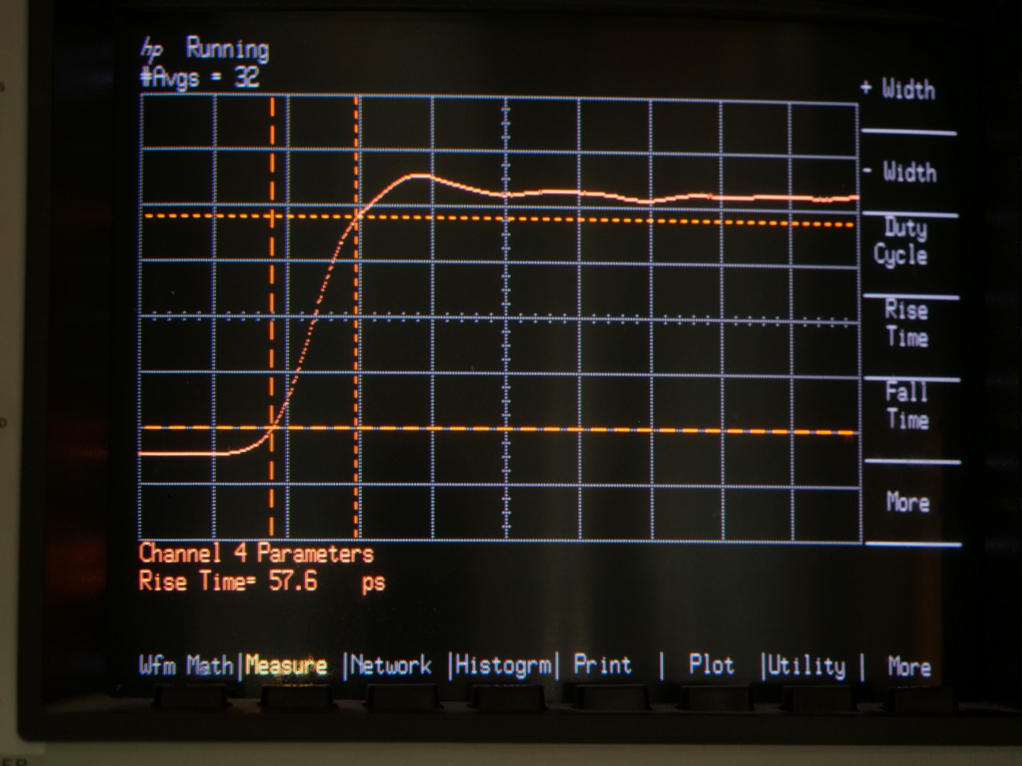
57.6ps on a 20GHz HP 54120B/54121A setup, but as this uses 3.5mm/SMA connectors, I very strongly suspect the limitation is my professionally terminated BNC-SMA cable. The best I could get out of the cable from the internal <33ps rise time TDR output of the 54121A test set with that cable (and a further BNC/SMA transition) was about the same. I tried a number of BNC/SMA interseries connectors of assorted qualities (none that I'd call professional) as well as the 12" RG223 SMA-M/BNC-F cable, and the cable gave the best results.
Hi,
Data from
mk_ and
Howardlong has been added, so has my own 2465B:
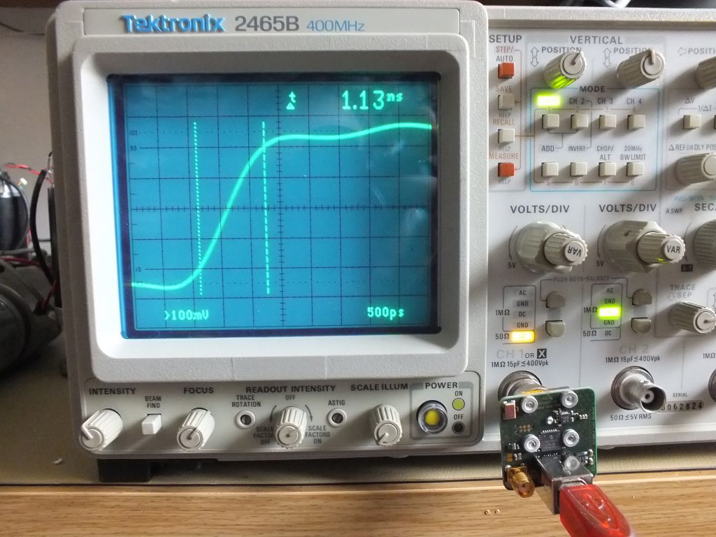
It does not quite live up to it's specification or I'm doing something wrong with it using the 10x mag
Hi,
Data from mk_ and Howardlong has been added, so has my own 2465B:
It does not quite live up to it's specification or I'm doing something wrong with it using the 10x mag
It looks like your 500ps timebase is OK.
You need to adjust the vertical gain so that the square wave top is at the solid line above the top dotted line, and the square wave bottom is at the solid line below the lower dotted line. Then the two dotted lines will be at 10% and 90%. Set the two cursors where the trace crosses the 10% and 90% dotted lines.
That should give a better result.
Also, I've noticed on my analog scopes, the shape of the trace varies some between channels. Is that because the analog scopes are old and need some TLC? Or was there that much variation when they were new? I don't know.
You might want to try 1 and 2 to see if there is a noticeable difference.
You need to adjust the vertical gain so that the square wave top is at the solid line above the top dotted line, and the square wave bottom is at the solid line below the lower dotted line. Then the two dotted lines will be at 10% and 90%. Set the two cursors where the trace crosses the 10% and 90% dotted lines.
His measurement is correct. Waveform's top and bottom should be on the dotted lines(!) and then the next solid line is the 10% and 90%. This is even marked on the overlay in the photo.
You are right! The few times I've ever needed to measure rise time I never bothered to look at the scale. I just went with my faulty memory of what I once knew. Thanks for setting me straight.
Now I need to go back and redo my Tek analog scope measurements.
Tom
