Author Topic: $20 LCR ESR Transistor checker project  (Read 3451844 times)

bffargo and 21 Guests are viewing this topic.

Offline bitseeker

  • Super Contributor
  • ***
  • Posts: 9057
  • Country: us
  • Lots of engineer-tweakable parts inside!
Re: $20 LCR ESR Transistor checker project
« Reply #4650 on: April 04, 2018, 05:32:09 pm »
My point was that, if anyone were to offer a pre-assembled device with a simple repository of builds (actually, just one or two), it would go a long way towards solving the problem.

So, something like order a batch of a particular model (e.g., AY-AT) from China (hopefully, at a discount) to resell with a case and CD of the latest k and m firmware (binary and source) for it (and/or flash it with the latest).

Quote
The real problem, as others are pointing out, is that any decent quality kit, once the cost of the better components, assembly and shipping are taken into account, would be too expensive for most users (or has to be sold at cost, making it a bad proposition for whoever assembles it)

Yeah, which is likely the reason it's not been done. I'm still amazed that the companies in China are willing to make it available so inexpensively since it's pretty niche.
TEA is the way. | TEA Time channel
 

Offline Argiros

  • Contributor
  • Posts: 10
  • Country: 00
Re: $20 LCR ESR Transistor checker project
« Reply #4651 on: April 05, 2018, 02:21:14 am »
Dear friends, finally after a long time and when the mc ATMega328p came for my bricked GM328B, I desolder as I promised the smd mc and put a  new one and everything was ok! Also I managed to program it to new versions for ex v1.29 by Markus (amazing  compared to my original crappy one) and I also put from Karl  the Mega328_colorkit version for testing it. Although I have and the good rotary GM328A version board, but I like more to play with the GM328B. This B model has 2 buttons only and it is pathetic. The one btn is the reset and doing only reset, and the other is the select button. To getting to the menu to selecting items and to get back is impossible like the rotary one. 
      And here is my question :

Can I add a rottary switch button to this model GM328B ? Where I can solder this ?

or else can I add 3 more buttons for using them for scrolling up down and for back ?

I use avr-gcc ver 4.9. Which compiler version is the best because the older makes big files and the newer are making errors. Is there any other compiler - program better ?

Thank you all for your help and a very big THANK YOU to our leader MADIRES!  :-+ you are the best man!
« Last Edit: April 05, 2018, 10:27:21 am by Argiros »
 

Offline timelessbeing

  • Frequent Contributor
  • **
  • Posts: 929
  • Country: 00
Re: $20 LCR ESR Transistor checker project
« Reply #4652 on: April 05, 2018, 06:06:51 am »
Karl's documentation has schematics which show how you can connect a rotary encoder. The documentation is pretty much required reading for anybody wanting to make modifications.

GCC problems.
« Last Edit: April 05, 2018, 06:08:57 am by timelessbeing »
 
The following users thanked this post: Argiros

Offline madires

  • Super Contributor
  • ***
  • Posts: 7767
  • Country: de
  • A qualified hobbyist ;)
Re: $20 LCR ESR Transistor checker project
« Reply #4653 on: April 05, 2018, 10:19:04 am »
Can I add a rottary switch button to this model GM328B ? Where I can solder this ?

or else can I add 3 more buttons for using them for scrolling up down and for back ?

You can use two push buttons for up/down (increase/decrease) instead of a rotary encoder (k-firmware: WITH_ROTARY_SWITCH 4, m-firmware: HW_INCDEC_KEYS, and check the portpins). The test button is mandatory, either as a separate push button or integrated in the rotary encoder. And there's no back button. As timelessbeing already has mentioned, the wiring is explained in Karl-Heinz' documentation.
 
The following users thanked this post: Argiros

Offline daemon123

  • Contributor
  • Posts: 16
  • Country: pk
Re: $20 LCR ESR Transistor checker project
« Reply #4654 on: April 06, 2018, 04:47:20 pm »
Hi,
is there firmware with support for  STE2007 96 x 68 Single Chip LCD Controller/Driver ?
 

Offline madires

  • Super Contributor
  • ***
  • Posts: 7767
  • Country: de
  • A qualified hobbyist ;)
Re: $20 LCR ESR Transistor checker project
« Reply #4655 on: April 06, 2018, 06:17:21 pm »
No, the STE2007 isn't supported. But based on the datasheet it shouldn't be hard to write a driver.
 

Offline Argiros

  • Contributor
  • Posts: 10
  • Country: 00
Re: $20 LCR ESR Transistor checker project
« Reply #4656 on: April 12, 2018, 09:55:20 am »
<madires>: Are you saying that I cannot add a rotary button but only the 2 buttons ? or I can add them either one or the other ? or maybe both rotary and buttons ?

I think I found some of the answers through Karls doc:
this schematic is explaining much. The only thing I dont know yet is if I can use both rotary and buttons through software issues.

« Last Edit: April 12, 2018, 10:47:06 am by Argiros »
 

Offline madires

  • Super Contributor
  • ***
  • Posts: 7767
  • Country: de
  • A qualified hobbyist ;)
Re: $20 LCR ESR Transistor checker project
« Reply #4657 on: April 12, 2018, 10:45:02 am »
k-firmware: You can add either a rotary encoder or two push buttons (up/down).
m-firmware: You can add a rotary encoder, two push buttons (increase/decrease) and a touch screen. Usually you would add only one because the ATmega328 doesn't provide enough I/O pins and all three do the same - just in a different way.
 
The following users thanked this post: Argiros

Offline rddube

  • Regular Contributor
  • *
  • Posts: 92
  • Country: ca
Re: $20 LCR ESR Transistor checker project
« Reply #4658 on: April 12, 2018, 12:39:39 pm »
Hello Everyone,

I bought 2 of the attached tester and installed the M version on one and the K version on the other. The one with the K version burnt the chip (v05 - diode array) and then the main chip. Should I be modifying it to use the K version? Also, with the M version, if there is nothing in the tester it gives me a reading of a capacitor of 15 pf, but seems to work ok otherwise.

I installed the latest version for both firmwares.

Any help would be appreciated. This model has the input protection circuit as you can see on the back.
« Last Edit: April 12, 2018, 12:41:50 pm by rddube »
 

Offline madires

  • Super Contributor
  • ***
  • Posts: 7767
  • Country: de
  • A qualified hobbyist ;)
Re: $20 LCR ESR Transistor checker project
« Reply #4659 on: April 12, 2018, 01:23:28 pm »
I think I found some of the answers through Karls doc:
this schematic is explaining much. The only thing I dont know yet is if I can use both rotary and buttons through software issues.

The rotary encoder and the alternative two push buttons are wired exactly the same way. With the k-firmware you can have only one of both. Anyway, it doesn't make much sense to have both because they provide the same function (up and down). Also the ATmega328 doesn't have enough I/O pins for connecting both. If you prefer push buttons over a rotary encoder then choose the push buttons, or vice versa.
 

Offline madires

  • Super Contributor
  • ***
  • Posts: 7767
  • Country: de
  • A qualified hobbyist ;)
Re: $20 LCR ESR Transistor checker project
« Reply #4660 on: April 12, 2018, 01:44:43 pm »
I bought 2 of the attached tester and installed the M version on one and the K version on the other. The one with the K version burnt the chip (v05 - diode array) and then the main chip. Should I be modifying it to use the K version? Also, with the M version, if there is nothing in the tester it gives me a reading of a capacitor of 15 pf, but seems to work ok otherwise.

A few users with the kit version of your tester had problems with the placement of the SRV05-4. When reversed the internal TVS diode will short Vcc to ground. Since it's an optional (weak) input protection the tester will also work without it. After programming the firmware please run the self-adjustment and the 15pF issue will vanish.
 

Offline rddube

  • Regular Contributor
  • *
  • Posts: 92
  • Country: ca
Re: $20 LCR ESR Transistor checker project
« Reply #4661 on: April 12, 2018, 06:43:44 pm »

[/quote]

A few users with the kit version of your tester had problems with the placement of the SRV05-4. When reversed the internal TVS diode will short Vcc to ground. Since it's an optional (weak) input protection the tester will also work without it. After programming the firmware please run the self-adjustment and the 15pF issue will vanish.
[/quote]

Hello Madires,

Are you saying that I could simply remove the SRV05 and work it that way? This was not a kit version, so I didn't install it.  But if you are saying that it is almost useless, then I will simply remove it. Please confirm and tks!
 

Offline madires

  • Super Contributor
  • ***
  • Posts: 7767
  • Country: de
  • A qualified hobbyist ;)
Re: $20 LCR ESR Transistor checker project
« Reply #4662 on: April 12, 2018, 06:50:05 pm »
The SRV05-4 isn't useless but the tester works also fine without it. Make sure you discharge any capacitor before testing.
 

Offline TechieTX

  • Contributor
  • Posts: 41
  • Country: us
Re: $20 LCR ESR Transistor checker project
« Reply #4663 on: April 13, 2018, 01:04:53 am »
I use one of the surface-mount test pads to discharge caps on the AY-AT.  They're a handy bit of metal near the ZIF socket.  Of course be careful to hit only ONE of the pads with both legs of the cap, or POOF! goes your tester.  Several other boards have something similar you can use.


I discharge all caps (regardless of type or 'built-in protection' on the board) as I've seen a number of folks complain that they've fried their tester.  My ATmega is socketed, but I don't have an endless supply of them.
"No matter where you go, there you are." ~BB
 

Offline JonnieCache

  • Contributor
  • Posts: 23
  • Country: us
Re: $20 LCR ESR Transistor checker project
« Reply #4664 on: April 13, 2018, 01:41:22 am »
I use one of the surface-mount test pads to discharge caps on the AY-AT.  They're a handy bit of metal near the ZIF socket.  Of course be careful to hit only ONE of the pads with both legs of the cap, or POOF! goes your tester.  Several other boards have something similar you can use.


I discharge all caps (regardless of type or 'built-in protection' on the board) as I've seen a number of folks complain that they've fried their tester.  My ATmega is socketed, but I don't have an endless supply of them.

I'm pretty sure that is the same thing as shorting out the capacitor. I'm not an expert, but I'm also pretty sure that is not good for the capacitor.
 

Offline Distelzombie

  • Frequent Contributor
  • **
  • Posts: 283
  • Country: de
Re: $20 LCR ESR Transistor checker project
« Reply #4665 on: April 13, 2018, 04:04:14 am »
How is the pad on the board any more better than the metal arm of the contact-array thingy?

Offline JonnieCache

  • Contributor
  • Posts: 23
  • Country: us
$20 LCR ESR Transistor checker project
« Reply #4666 on: April 13, 2018, 09:31:36 am »
How is the pad on the board any more better than the metal arm of the contact-array thingy?

It’s not. It’s the same. It is meant for testing SMDs. When testing a capacitor, you should always make sure that it is discharged before testing it. Otherwise, you could damage the tester or yourself.

The proper way to discharge a capacitor is not by shorting out the two leads. By following the advice above (putting both leads on the same pad) you are doing just that. It’s no different than if you connected the leads together themselves or with a bit of wire. I would not follow the advice above for discharging. It is a hazard and can damage the capacitor.

If you do a search on the web about discharging a capacitor safely, you can find all sorts of solutions. Some are as simple as using a resistor to connect to the leads of the capacitor. While not great for all situations, at least that would not create a short. Make sure that the discharge circuit you are using will properly handle the amount of current and voltage that the capacitor may deliver.

The ideal solution is to purchase or build a simple device with proper current protection using a series of diodes and two LEDs. So, you will be able to see visually when the capacitor is discharged enough to be handled safely.

Something like this would do the job:

http://www.instructables.com/id/Safe-Capacitor-Discharge-Tool/
 

Offline misterno

  • Contributor
  • Posts: 33
  • Country: gr
Re: $20 LCR ESR Transistor checker project
« Reply #4667 on: April 13, 2018, 09:34:58 am »
I 've post here because it looks like my own problem.

A good friend gave me a component tester with a 128X64 LCD screen like this one. The logo says: Mtester 2.07

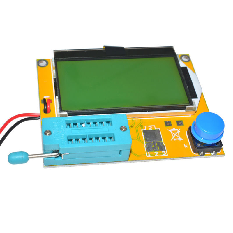
The problem is that once i plug in the battery and press the button, the display shows the home screen and the message "... Starting"
After about 20 seconds, it shows the battery cell symbol and says "cell 53mV" by changing each time the button is pressed this 53mV in different values.
After I pulled out and measured all the semiconductors, resistors, capacitors etc and after I measured the voltage in the circuit and I found it 5V, I 've tried
to read the ATMEGA328P code but no luck.

I connect the cables to the SCK, MISO, MOSI, RST, GND, VCC to my TL866A programmer i have and try to read the program.
The developer read "successfully," as the program said, but did not show anything either in the code window or in the data.
Since nothing was done, I decided to clear the MCU and reprogram it. I load the HEX code I found and i was going to flash it.
I ended up with an error message and also i 've erased the signature ID of the chip (from 1E 95 0F to 00 00 00).

I change tactics and convert an arduino mega to ISP. I run the avrdude program with the appropriate parameters and control bits after I had
get backup of flash files, efuse, lock etc.
I tried the "erase" command but no luck. I also played with -F for testing.

The chip said it had been programmed, but the device did not understand anything, and continued to turn on the display and show the signal of the cell and the message "cell 53mV"

Is it any possibility to do a forcing flash to the chip?

Now I am in the process of ordering a new ATMEGA328P with a 8MHz clock as well as the original one.

Is it anything else i can try until its arrival?
TIA
« Last Edit: April 13, 2018, 09:39:54 am by misterno »
 

Offline bugi

  • Regular Contributor
  • *
  • Posts: 249
  • Country: fi
  • Hobbyist using the ultra slow and unsure method
Re: $20 LCR ESR Transistor checker project
« Reply #4668 on: April 13, 2018, 10:32:21 am »
The ideal solution is to purchase or build a simple device with proper current protection using a series of diodes and two LEDs. So, you will be able to see visually when the capacitor is discharged enough to be handled safely.
My quick and dirty slightly overkill capacitor discharger arrangement, using bunch of resistors, couple screw terminal thingies and two leads I happened to have available. Leads are long enough to keep that monster a safe distance away (no protections/case on it so for a short moment it could be dangerous to touch). I used to it to discharge PSU primary side caps, which is why so high resistance and power handling, but for lower voltages I just move the other lead to another point along the resistor chain. This is not for the most impatient person, but for me, it is better as it "forces" to give a little bit extra time to think what I'm about to do (or if I should do) next, while waiting the high voltages to drain down. Quick enough for me.

(EDIT: note, certainly not "CAT anything" on the "probing end", but tested in practice...)
« Last Edit: April 13, 2018, 10:37:35 am by bugi »
 

Offline JonnieCache

  • Contributor
  • Posts: 23
  • Country: us
Re: $20 LCR ESR Transistor checker project
« Reply #4669 on: April 13, 2018, 10:54:20 am »
My quick and dirty slightly overkill capacitor discharger arrangement, using bunch of resistors, couple screw terminal thingies and two leads I happened to have available.

Wow! You get extra points for style! I love it! You are so right to take the extra time to think about it before you do it. I have to remind myself of that sometimes, too. Yours will certainly handle any necessary voltage! I still like to have the LEDs to make sure that it is adequately discharged, but that's just me. If you do the math (admittedly not hard) and have the right resistance (and time), you're good to go! VERY COOL!
 

Offline madires

  • Super Contributor
  • ***
  • Posts: 7767
  • Country: de
  • A qualified hobbyist ;)
Re: $20 LCR ESR Transistor checker project
« Reply #4670 on: April 13, 2018, 10:55:12 am »
The chip said it had been programmed, but the device did not understand anything, and continued to turn on the display and show the signal of the cell and the message "cell 53mV"

Some manufacturers set the lock bits and you have to erase the complete ATmega to be able to program a new firmware. The "cell" message is displayed when the tester detects a voltage at one of the probe pins. It can be caused by a fried MCU pin or some leakage current (PCB, ZIF socket, etc.).
 

Offline madires

  • Super Contributor
  • ***
  • Posts: 7767
  • Country: de
  • A qualified hobbyist ;)
Re: $20 LCR ESR Transistor checker project
« Reply #4671 on: April 13, 2018, 11:18:30 am »
My quick and dirty slightly overkill capacitor discharger arrangement, using bunch of resistors, couple screw terminal thingies and two leads I happened to have available.

I've simply taken a small plastic box with four 4mm banana jacks used for a voltage regulator before, connected inputs and outputs with a solid copper wire, soldered the next best power resistor (560 Ohms, 5 or 7W) across the red and black jacks and attached some old DMM probe leads. The "output" jacks can be used for monitoring the voltage with a DMM/VTVM. The only new part was the label I've printed ;)
 
The following users thanked this post: JonnieCache

Offline misterno

  • Contributor
  • Posts: 33
  • Country: gr
Re: $20 LCR ESR Transistor checker project
« Reply #4672 on: April 13, 2018, 11:28:11 am »
The chip said it had been programmed, but the device did not understand anything, and continued to turn on the display and show the signal of the cell and the message "cell 53mV"

Some manufacturers set the lock bits and you have to erase the complete ATmega to be able to program a new firmware. The "cell" message is displayed when the tester detects a voltage at one of the probe pins. It can be caused by a fried MCU pin or some leakage current (PCB, ZIF socket, etc.).

That's i would to do i like to erase completely the chip but my programmers refuse to do it. Is there anyway to force erasing it? I will try to isolate the pins from the socket though to see if i keep on having the "cell" error.
 

Offline rddube

  • Regular Contributor
  • *
  • Posts: 92
  • Country: ca
Re: $20 LCR ESR Transistor checker project
« Reply #4673 on: April 13, 2018, 11:49:25 am »
I 've post here because it looks like my own problem.


Have the exact same tester and very similar problems to what you are experiencing. Turned out the main chip was damaged, so I changed it and got the tester to run perfectly again..it's been almost over a year, and it's still going strong.

In retrospect, I started thinking why was the main chip damaged, and I remember doing some in circuit ESR testing and at some point something felt weird when checking a capacitor and bang that was it, it was charged and damaged the Atmega328P of my unit.
 
The following users thanked this post: misterno

Offline misterno

  • Contributor
  • Posts: 33
  • Country: gr
Re: $20 LCR ESR Transistor checker project
« Reply #4674 on: April 13, 2018, 12:39:42 pm »
I 've post here because it looks like my own problem.


Have the exact same tester and very similar problems to what you are experiencing. Turned out the main chip was damaged, so I changed it and got the tester to run perfectly again..it's been almost over a year, and it's still going strong.

In retrospect, I started thinking why was the main chip damaged, and I remember doing some in circuit ESR testing and at some point something felt weird when checking a capacitor and bang that was it, it was charged and damaged the Atmega328P of my unit.

You saved me from bad troubleshooting then. By the way i was wondering if its possible to simulate the 128X64 LCD used in this device as a VSM proteus project.
I looked for it into the web but no luck. It would be nice approach to this thread.


Share me

Digg  Facebook  SlashDot  Delicious  Technorati  Twitter  Google  Yahoo
Smf