Author Topic: Siglent SDS2000X Plus  (Read 747546 times)

0 Members and 4 Guests are viewing this topic.

Online tautechTopic starter

  • Super Contributor
  • ***
  • Posts: 28511
  • Country: nz
  • Taupaki Technologies Ltd. Siglent Distributor NZ.
    • Taupaki Technologies Ltd.
Re: Siglent SDS2000X Plus
« Reply #2425 on: February 28, 2021, 06:16:51 pm »
thanks again tautech, yes i did see that thread too,
just did not find the one important line i was looking for :-)
did anyone confirm by really trying ? to use any of the other brands LA into a siglent ?
and all channels works, all show up at correct numbers ?
As the LA probes in that post are of other brands and identical for all intensive purposes I don't see any reason why they won't work just fine.
Like scope probes they are extremely likely not to be made by the scope manufacturers but some speciality probe company and rebranded to suit the scope OEM.

Quote
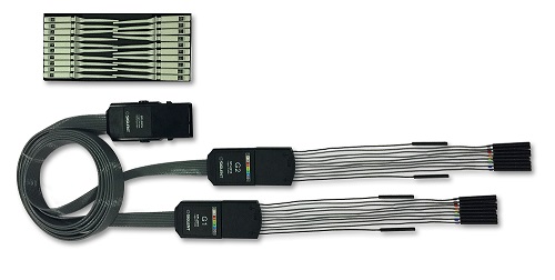
but I did find a few decent pictures of the connector and the press release and buttons,
from this i got the idea: let me drop my own home invented 3D design,
and much rather make one that looks a lot more like the original :-)
but for this, I need a lot more and better pictures, also prefered on the internal parts, how easy is it to open ?
please PM or Email me pictures ? if you got the time, Thanks in Advance.
Certainly I can post some pics if necessary or take some measurements.

Yes the release catch is nice yet I wonder for the careful user if it is necessary when we could maybe rely on the friction fit into the PCi-E socket instead.
I've looked at opening the ribbon cable breakouts however they appear to be welded shut so I'd prefer not to scalpel blade them open and risk making a mess as these are my demo LA probes for when I'm out and about at shows or at customers.
Someone instead needs to Xray them so to see if there's any active or passive circuitry inside although if TK was able to make old HPAK LA cables work with just an adapter maybe there are clues in how HPAK LA cables are constructed that can also be applied to a DIY set.

IMO crosstalk can be addressed like it was with 80 conductor IDE ribbon cables have a dead/null conductor between each active one although once you've handled a real SPL2016 with their twin narrow and supple 8pr legs you wouldn't want to make something too dissimilar. I suspect the 8 conductor cable has a shield on each conductor for them to really be an 8 way coax ribbon cable...haven't gone searching for these yet.
Also their breakout ends and their extremely supple fine silicon cables for each grabber are very nice.
This EZ Hook grabber is supplied with SPL2016:
https://e-z-hook.com/test-hooks/micro-hook/xkm-micro-test-hook-double-gripper-with-0-025-in-square-pins/

For mawyatt
Breakouts are on 20 pin plugs with 10 flying leads in total with 2 Ref/Gnd leads ~120mm and 8 further leads ~180mm long. Gnd/Ref leads are 0 Ohms through whilst all others measure 91 Ohms.
Avid Rabid Hobbyist.   Come visit us at EMEX Stand #1001 https://www.emex.co.nz/
Siglent Youtube channel: https://www.youtube.com/@SiglentVideo/videos
 
The following users thanked this post: mawyatt

Offline mawyatt

  • Super Contributor
  • ***
  • Posts: 3341
  • Country: us
Re: Siglent SDS2000X Plus
« Reply #2426 on: February 28, 2021, 06:20:57 pm »
Ok, this has got my curiosity going and we've just played around a little with the Digital option on the SDS2102X Plus we have. First time I've looked at this since we had no logic probe, thus no need to consider this Digital option. It appears the active circuitry is within the scope since you can change things which require an offset threshold to get the logic bit to toggle. This was confirmed by passing a squarewave from the AWG set to 2VPP with 1V offset, so 0 to 2V. Used a 100K resistor to very carefully poke this AWG signal into the scope connector with one hand on the scope ground at all times. If the logic threshold was default to 0 then no change in the displayed logic waveform was observed when the resistor lead touched the connector logic bit pin, however with the logic threshold set to 1V then the logic bit began to toggle when the 100K resistor lead touched the connector pin.

So it appears a completely passive logic probe is in order since the supporting bit sensing circuits are already within the scope, nice touch Siglent!!

Best,
Curiosity killed the cat, also depleted my wallet!
~Wyatt Labs by Mike~
 

Offline oz2cpu

  • Frequent Contributor
  • **
  • Posts: 850
  • Country: dk
    • webx.dk private hobby and diy stuff
Re: Siglent SDS2000X Plus
« Reply #2427 on: February 28, 2021, 06:45:16 pm »
exactly mike
all we need is an easy and simple way to access the pins
that is what my brake out pcb does, and I also made a nice 3D print to hold it
« Last Edit: February 28, 2021, 06:49:37 pm by oz2cpu »
Radioamateur OZ2CPU, Senior EE at Prevas
EMC RF SMPS SI PCB LAYOUT and all that stuff.
 
The following users thanked this post: mawyatt

Offline mawyatt

  • Super Contributor
  • ***
  • Posts: 3341
  • Country: us
Re: Siglent SDS2000X Plus
« Reply #2428 on: February 28, 2021, 07:04:50 pm »
For mawyatt
Breakouts are on 20 pin plugs with 10 flying leads in total with 2 Ref/Gnd leads ~120mm and 8 further leads ~180mm long. Gnd/Ref leads are 0 Ohms through whilst all others measure 91 Ohms.

Maybe the 91 ohms matches the coaxial bit line cable impedance from the pods back to the base?

Best,
Curiosity killed the cat, also depleted my wallet!
~Wyatt Labs by Mike~
 

Offline oz2cpu

  • Frequent Contributor
  • **
  • Posts: 850
  • Country: dk
    • webx.dk private hobby and diy stuff
Re: Siglent SDS2000X Plus
« Reply #2429 on: February 28, 2021, 07:07:42 pm »
where exactly ? and how did you measure 91 ohms
I am a bit confused, please help us ?
Radioamateur OZ2CPU, Senior EE at Prevas
EMC RF SMPS SI PCB LAYOUT and all that stuff.
 

Online tautechTopic starter

  • Super Contributor
  • ***
  • Posts: 28511
  • Country: nz
  • Taupaki Technologies Ltd. Siglent Distributor NZ.
    • Taupaki Technologies Ltd.
Re: Siglent SDS2000X Plus
« Reply #2430 on: February 28, 2021, 07:35:18 pm »
where exactly ? and how did you measure 91 ohms
I am a bit confused, please help us ?
For each of the longer coloured leads in the breakout.

For mawyatt
Breakouts are on 20 pin plugs with 10 flying leads in total with 2 Ref/Gnd leads ~120mm and 8 further leads ~180mm long. Gnd/Ref leads are 0 Ohms through whilst all others measure 91 Ohms.

Avid Rabid Hobbyist.   Come visit us at EMEX Stand #1001 https://www.emex.co.nz/
Siglent Youtube channel: https://www.youtube.com/@SiglentVideo/videos
 

Offline oz2cpu

  • Frequent Contributor
  • **
  • Posts: 850
  • Country: dk
    • webx.dk private hobby and diy stuff
Re: Siglent SDS2000X Plus
« Reply #2431 on: February 28, 2021, 07:59:52 pm »
yes that clearly makes sense, the Good TK also helped me with the resistors and CAPACITOR,
there is infact a speed up capacitor inside the HP cable set, over the 92k resistor,
TK found this important detail in the HP docs, and kindly informed me about it.. Thanks mate..
Radioamateur OZ2CPU, Senior EE at Prevas
EMC RF SMPS SI PCB LAYOUT and all that stuff.
 
The following users thanked this post: TK

Offline oz2cpu

  • Frequent Contributor
  • **
  • Posts: 850
  • Country: dk
    • webx.dk private hobby and diy stuff
Re: Siglent SDS2000X Plus
« Reply #2432 on: February 28, 2021, 08:24:48 pm »
time to try your 3D printer ?
https://www.thingiverse.com/thing:4779225

what is the Color code ? or name ? of the Siglent units ?
now I will try and see if I can get 3D printing filament in a color that is close, i down own a color meter.
Radioamateur OZ2CPU, Senior EE at Prevas
EMC RF SMPS SI PCB LAYOUT and all that stuff.
 

Offline mawyatt

  • Super Contributor
  • ***
  • Posts: 3341
  • Country: us
Re: Siglent SDS2000X Plus
« Reply #2433 on: March 01, 2021, 05:17:29 pm »
Do these Logic Analyzer lines have a series 91 ohm resistor in the front of the POD to the probe wire, followed by a parallel 92K resistor and unknown value cap to feed the longer cable with individual coaxial lines back the base that plugs into the scope?

If correct, wonder if this to terminate the coaxial cable at the input with 91 ohms series, the bypass of the 92K resistor with a cap which would pass the signal edge to the coaxial cable. If the cable were terminated at the base, or inside the scope, with an AC coupled 91 ohms to ground, then the signal edge would "see" a terminated coaxial transmission line and no reflexions to disrupt the edge detection. So the logic signal edge would "see" a 91 ohm terminated cable if fast enough, but a slower edge would "see" a higher impedance, and both type logic signals would pass the full waveform upper and lower levels based upon the time constants involved.

Anyway, just thinking out loud as to how this might work. Anyone else have some ideas about this?

Best,
Curiosity killed the cat, also depleted my wallet!
~Wyatt Labs by Mike~
 

Offline oz2cpu

  • Frequent Contributor
  • **
  • Posts: 850
  • Country: dk
    • webx.dk private hobby and diy stuff
Re: Siglent SDS2000X Plus
« Reply #2434 on: March 01, 2021, 05:32:08 pm »
here you go Mike
this is the probe tip from HP
the good TK found this info.

I want to split the 250 ohm into two resistors, like this:
i expect the two 120 ohm needs to match the cable used,
and also trim the value of the 8.2pF for hi speed performance,

see attached
Radioamateur OZ2CPU, Senior EE at Prevas
EMC RF SMPS SI PCB LAYOUT and all that stuff.
 

Offline mawyatt

  • Super Contributor
  • ***
  • Posts: 3341
  • Country: us
Re: Siglent SDS2000X Plus
« Reply #2435 on: March 01, 2021, 06:11:55 pm »
Thanks.

The 3M twisted pair ribbon cable I found has a 137 ohm balanced and 103 ohm unbalanced impedance. The load equivalent (scope side) is not what I expected tho. Need to spend some time looking into how this works.

http://www.farnell.com/datasheets/1377874.pdf

Best,
Curiosity killed the cat, also depleted my wallet!
~Wyatt Labs by Mike~
 

Offline oz2cpu

  • Frequent Contributor
  • **
  • Posts: 850
  • Country: dk
    • webx.dk private hobby and diy stuff
Re: Siglent SDS2000X Plus
« Reply #2436 on: March 01, 2021, 06:30:50 pm »
exactly mike, it dont need to be any closer than this :-)
Radioamateur OZ2CPU, Senior EE at Prevas
EMC RF SMPS SI PCB LAYOUT and all that stuff.
 

Offline TK

  • Super Contributor
  • ***
  • Posts: 1722
  • Country: us
  • I am a Systems Analyst who plays with Electronics
Re: Siglent SDS2000X Plus
« Reply #2437 on: March 01, 2021, 06:40:54 pm »
here you go Mike
this is the probe tip from HP
the good TK found this info.

I want to split the 250 ohm into two resistors, like this:
i expect the two 120 ohm needs to match the cable used,
and also trim the value of the 8.2pF for hi speed performance,

see attached
I sacrificed a probe cable... here is the picture.  The resistors and capacitor are located at the tip of the probe, very close to the end (1-2 inches).
 

Offline oz2cpu

  • Frequent Contributor
  • **
  • Posts: 850
  • Country: dk
    • webx.dk private hobby and diy stuff
Re: Siglent SDS2000X Plus
« Reply #2438 on: March 01, 2021, 06:49:24 pm »
so it is like this ?
R1 falled of ?  350 R
C1 8p2
R2 92k
R3 ?
Radioamateur OZ2CPU, Senior EE at Prevas
EMC RF SMPS SI PCB LAYOUT and all that stuff.
 

Online tautechTopic starter

  • Super Contributor
  • ***
  • Posts: 28511
  • Country: nz
  • Taupaki Technologies Ltd. Siglent Distributor NZ.
    • Taupaki Technologies Ltd.
Re: Siglent SDS2000X Plus
« Reply #2439 on: March 01, 2021, 06:58:09 pm »
Smart tweezer across Gnd/Ref lead and channel lead of the breakout pod disconnected from the LA cable = 6.5-8.5 pF.

Not that my tweezers are very accurate with low capacitance measurements but do indeed indicate a shunt capacitance across each lead.
Avid Rabid Hobbyist.   Come visit us at EMEX Stand #1001 https://www.emex.co.nz/
Siglent Youtube channel: https://www.youtube.com/@SiglentVideo/videos
 

Offline TK

  • Super Contributor
  • ***
  • Posts: 1722
  • Country: us
  • I am a Systems Analyst who plays with Electronics
Re: Siglent SDS2000X Plus
« Reply #2440 on: March 01, 2021, 07:07:56 pm »
so it is like this ?
R1 falled of ?  350 R
C1 8p2
R2 92k
R3 ?
I added the values on the image but for some reason was not saved

Resistor on the left is 250 ohms, on the right is 90.1 Kohms in parallel with the 8.2pF capacitor
 
The following users thanked this post: mawyatt

Offline mawyatt

  • Super Contributor
  • ***
  • Posts: 3341
  • Country: us
Re: Siglent SDS2000X Plus
« Reply #2441 on: March 01, 2021, 08:51:57 pm »
Here's a simulation using the circuits and values provided for the HP (TK) and Custom (oz2cpu) Logic Probes. Stimulus is from an ideal source with 1ns rise and fall at 5v, logic gate is modeled a simple series R of 50 ohms. Probe lead cable back to scope is modeled a 137 ohm transmission line of 2ns long (twisted pair 402mm assuming vel C=0.67).

Note how the HP circuit perturbs the gate waveform less at the edge, has a flatter response but lower amplitude, and is somewhat faster rise and fall times.

Note this HP result is likely because the 250 ohm, 90.9K and 8.2pF are "pushed" out closer to the inputs ahead of the 137 ohm twisted pair transmission cable.

Best,
« Last Edit: March 01, 2021, 09:04:04 pm by mawyatt »
Curiosity killed the cat, also depleted my wallet!
~Wyatt Labs by Mike~
 

Offline oz2cpu

  • Frequent Contributor
  • **
  • Posts: 850
  • Country: dk
    • webx.dk private hobby and diy stuff
Re: Siglent SDS2000X Plus
« Reply #2442 on: March 01, 2021, 10:12:42 pm »
fantastic Mike, I am now sure we are going to win over this "problem"
EDIT:
new isolated thread for this topic:
https://www.eevblog.com/forum/testgear/diy-logic-analyzer-probe-and-pods-for-siglent-scopes/
« Last Edit: March 05, 2021, 08:50:47 am by oz2cpu »
Radioamateur OZ2CPU, Senior EE at Prevas
EMC RF SMPS SI PCB LAYOUT and all that stuff.
 

Offline zerto

  • Contributor
  • Posts: 13
  • Country: fr
Re: Siglent SDS2000X Plus
« Reply #2443 on: March 05, 2021, 02:22:57 pm »
Hello,

I have been following this thread from quite some time now, big thank you to the contributors: this is great to read such quality messages.
So I decided to sell my previous scope to buy the SDS2104X Plus. I'm a hobbyist and this was the kind of scope that I would not think I could afford.
What a great value for the money, this is a fantastic scope !
The hardware version is 02-04 and I can confirm that the upgrade is still working (using Miyagi method with telnet https://www.eevblog.com/forum/testgear/siglent-sds2000x-plus-coming/msg3006340/#msg3006340)

I found something to improve regarding the Manchester decoding and I will publish a post on this topic in the bug/missing features thread.
 

Offline oz2cpu

  • Frequent Contributor
  • **
  • Posts: 850
  • Country: dk
    • webx.dk private hobby and diy stuff
Re: Siglent SDS2000X Plus
« Reply #2444 on: March 05, 2021, 03:21:15 pm »
cool about reporting bugs / missing features or feature requests
but are any one from the Siglent sw development team reading here ?
like is it wasted bytes ? or should it be addressed directly to them ?
do we have a hotline ? or support email, they actually read ? or respond to ?
Radioamateur OZ2CPU, Senior EE at Prevas
EMC RF SMPS SI PCB LAYOUT and all that stuff.
 

Online Martin72

  • Super Contributor
  • ***
  • Posts: 5918
  • Country: de
  • Testfield Technician
Re: Siglent SDS2000X Plus
« Reply #2445 on: March 05, 2021, 06:27:35 pm »
Hi,

I think it will be recognized, also we got some user here, which are beta-testers for siglent.
Have a look at my signature, thereĀ“s also a general siglent support thread.
 
The following users thanked this post: oz2cpu

Offline profanum429

  • Regular Contributor
  • *
  • Posts: 56
  • Country: us
Re: Siglent SDS2000X Plus
« Reply #2446 on: March 06, 2021, 01:18:09 am »
I didn't want to clog up the DIY logic probe thread (since this isn't so much DIY) so I figured I'd ask here and see if anyone knew. I saw earlier that the Rigol RPL2316 look suspiciously like the SPL2016 logic probes, but they hold a little differently. They have a top latch instead of the side latch like the SPL2016; does anyone have any thoughts to if they'd work with this scope? I'm pretty sure they're the same design, just a slightly different case.

I only ask because I might be able to get a set of them pretty cheaply and that'd be a pretty good solution for me for logic probes.
 

Online tautechTopic starter

  • Super Contributor
  • ***
  • Posts: 28511
  • Country: nz
  • Taupaki Technologies Ltd. Siglent Distributor NZ.
    • Taupaki Technologies Ltd.
Re: Siglent SDS2000X Plus
« Reply #2447 on: March 06, 2021, 01:28:24 am »
I didn't want to clog up the DIY logic probe thread (since this isn't so much DIY) so I figured I'd ask here and see if anyone knew. I saw earlier that the Rigol RPL2316 look suspiciously like the SPL2016 logic probes, but they hold a little differently. They have a top latch instead of the side latch like the SPL2016; does anyone have any thoughts to if they'd work with this scope? I'm pretty sure they're the same design, just a slightly different case.

I only ask because I might be able to get a set of them pretty cheaply and that'd be a pretty good solution for me for logic probes.
It fitting into the LA probe housing opening might be an issue where you might need to trim down the plug some.

SPL2016 where it fits into the housing measures 28mm x 11mm.

Edit
Insertion depth is 24mm however the plug housing extends a little past the PCB and in doing so I believe wraps around the PCI-e socket on the mainboard.
« Last Edit: March 06, 2021, 01:39:02 am by tautech »
Avid Rabid Hobbyist.   Come visit us at EMEX Stand #1001 https://www.emex.co.nz/
Siglent Youtube channel: https://www.youtube.com/@SiglentVideo/videos
 
The following users thanked this post: profanum429

Offline mawyatt

  • Super Contributor
  • ***
  • Posts: 3341
  • Country: us
Re: Siglent SDS2000X Plus
« Reply #2448 on: March 06, 2021, 02:31:01 am »
I didn't want to clog up the DIY logic probe thread (since this isn't so much DIY) so I figured I'd ask here and see if anyone knew. I saw earlier that the Rigol RPL2316 look suspiciously like the SPL2016 logic probes, but they hold a little differently. They have a top latch instead of the side latch like the SPL2016; does anyone have any thoughts to if they'd work with this scope? I'm pretty sure they're the same design, just a slightly different case.

I only ask because I might be able to get a set of them pretty cheaply and that'd be a pretty good solution for me for logic probes.

Thought the Rigol has active circuitry, the Siglent is passive I believe.

Best,
Curiosity killed the cat, also depleted my wallet!
~Wyatt Labs by Mike~
 

Online tautechTopic starter

  • Super Contributor
  • ***
  • Posts: 28511
  • Country: nz
  • Taupaki Technologies Ltd. Siglent Distributor NZ.
    • Taupaki Technologies Ltd.
Re: Siglent SDS2000X Plus
« Reply #2449 on: March 06, 2021, 02:52:19 am »
I didn't want to clog up the DIY logic probe thread (since this isn't so much DIY) so I figured I'd ask here and see if anyone knew. I saw earlier that the Rigol RPL2316 look suspiciously like the SPL2016 logic probes, but they hold a little differently. They have a top latch instead of the side latch like the SPL2016; does anyone have any thoughts to if they'd work with this scope? I'm pretty sure they're the same design, just a slightly different case.

I only ask because I might be able to get a set of them pretty cheaply and that'd be a pretty good solution for me for logic probes.

Thought the Rigol has active circuitry, the Siglent is passive I believe.

Best,
Some Rigols use the same style LA probe as SPL2016 but the 5000 cheaped out and went for the wide ribbon cable LA probe which indeed has active componentry.
See this link:
https://www.tequipment.net/Rigol/RPL2316/Logic-Probes/
Avid Rabid Hobbyist.   Come visit us at EMEX Stand #1001 https://www.emex.co.nz/
Siglent Youtube channel: https://www.youtube.com/@SiglentVideo/videos


Share me

Digg  Facebook  SlashDot  Delicious  Technorati  Twitter  Google  Yahoo
Smf