I have few computer PSUs of various configurations laying around that are generic lower quality crap that I'd never use in an expensive new system. So (as it's obligatory) I decided to convert them into a bench power supplies, or at least make a project box they can plug into that would expose the different voltage rails as female banana plugs. I would maybe add some extra smoothing and possibly some extra precision voltage regulation and a few LEDs etc etc. You get the idea. The process looked simple, basically it's just a small checklist of things to do that should work with even the most obtuse PSUs. Boy was I wrong...
DELL NPS-300GB B REV:04
Connector:Non-Standard 24-Pin
I knew being dell that it would have non standard pin outs, so the internet once again came to the rescue.
Simply connecting PS_ON (Grey) to Ground (Black) turned the PSU on, no loads or anything else was needed. 5v rail read as 5.1v, 12v rail as 11.8v. (I'm assuming regulation is better under normal load, never had time to test this). Everything was good and confidence was high
FSP Group Inc (Generic crap) FSP350-60MDN Rev A
FSP Group Inc (Generic crap) FSP215-60PNA(PF)
Connector:Standard 20-Pin ATX
This is where I hit problems with both of them:
1. I shorted PS-ON (Green) with Ground (Black).. Nothing, but I know I needed a load
2. I added a 10ohm 5w WW resistor between +5 (Red) and Ground (Black).. Nothing.. Now I'm puzzled. This should have worked as it does with 90% of the videos and tutorials on the internet.
3. I did further research. It seems on rare occasions there's a "soft" power on, so I added a 25K resistor between +5 VSB (Purple) and Ground (Black)... Nothing... Head scratching began.
4. Tried a larger 112K resistor on +5v VSB (Purple), nothing
5. I added an old hard drive to another +5v rail for an additional load.. nothing.
6. I added a 10ohm load to the 12v rail as on even rarer occasions a load is needed on the +12v rail, nothing.
7. Checked that I hadn't somehow killed the PSUs, but both powered on when plugged into a computer
8. Went back to basics, maybe stupidity had kicked in.. Checked and rechecked.. nothing.
9. Stumped and mildly pissed off that something so simple got the better of me, So I went to the pub
Notes:
1. PSUs power on when connected to a computer. The PSU's fan rotates and connected HDD spins.
2. The +5v VSB registers as ~5v with a MM
3. PG (Gray) is not connected as it's just a power on indicator for an LED or other logic.
4. I tried momentary as well as constant connections on the PS-ON (Green) and also the +5v VSB (Purple lines)
Whatever I'm missing, it's got to be something really simple. I've spent too much time looking all over the internet and nothing has worked.
Help please! and Merry Christmas and a Happy New Year to all!
I know this will sound silly, but it's worth a try... the ATX connector has quite a lot of ground wires. Eight of them, which should all be connected together at the mainboard end as well as within the PSU. Should be. It's possible the PSU uses these to sense if it is properly connected, so maybe if you were to just link all the blacks together and then try connecting PS_ON to them all?
I can't think why any designer would do this, but when you've tried everything else you have to assume something weird is going on.
If the supplies work when connected to a PC then I'm sure you'll be able to sort it out before long. Try a subtractive approach, giving it small loads on all rails and the indicator. If it works, keep removing loads until it fails.
I'm going to be the obligatory doomsayer. You mentioned adding fancier voltage regulation, LEDs and so on. You didn't mention the most important thing, though. Even if it's a little more involved, please add current limiting. ATX power supplies will be happy to spot weld for you if invited, and everyone makes mistakes.
I know this will sound silly, but it's worth a try... the ATX connector has quite a lot of ground wires. Eight of them, which should all be connected together at the mainboard end as well as within the PSU. Should be. It's possible the PSU uses these to sense if it is properly connected, so maybe if you were to just link all the blacks together and then try connecting PS_ON to them all?
I can't think why any designer would do this, but when you've tried everything else you have to assume something weird is going on.
I'll give that a try mate. Thanks.
If the supplies work when connected to a PC then I'm sure you'll be able to sort it out before long. Try a subtractive approach, giving it small loads on all rails and the indicator. If it works, keep removing loads until it fails.
I'm going to be the obligatory doomsayer. You mentioned adding fancier voltage regulation, LEDs and so on. You didn't mention the most important thing, though. Even if it's a little more involved, please add current limiting. ATX power supplies will be happy to spot weld for you if invited, and everyone makes mistakes.
Thanks for reminding me /facepalm
ATX PSUs have a sense wire for the 3.3V rail. Usually, this is crimped into pin 11/13 with one of the 3.3V wires. Sometimes, especially on low power supplies, it has the pin all to itself. Make sure that's not the case.
ATX PSUs have a sense wire for the 3.3V rail. Usually, this is crimped into pin 11/13 with one of the 3.3V wires. Sometimes, especially on low power supplies, it has the pin all to itself. Make sure that's not the case.
As you mentioned, Pin 11 has both the +3.3v (Orange) and 3.3v Sense (Brown) crimped together on both PSUs. So It can't be that :/
It seems the power supplies you want to convert are unknown to you. Do they function normally? Try using them the way they were designed, then if they work ok they should work without the connection to the motherboard. I scored a bunch of the power supplies from the local metal recycler and half worked OK and the rest did not start up.
It seems the power supplies you want to convert are unknown to you. Do they function normally? Try using them the way they were designed, then if they work ok they should work without the connection to the motherboard. I scored a bunch of the power supplies from the local metal recycler and half worked OK and the rest did not start up.
As I mentioned in my opening post; They work in a computer, but I can't get them to work outside of a system. I've done extensive Googling and from roughly 15 videos and websites, what I've tried *should* have worked. It's very puzzling.
What I've not tried (which almost all videos do) is crimp or electrically connect all wires together by colour. The reason I've not done this is because I'd like to make what I'm doing into a project box that I can connect to any computer PSU instead of hard wired to a specific one. The potential issue here may relate to what @Monkeh mentioned earlier.
Here's the plan I followed which worked for me:
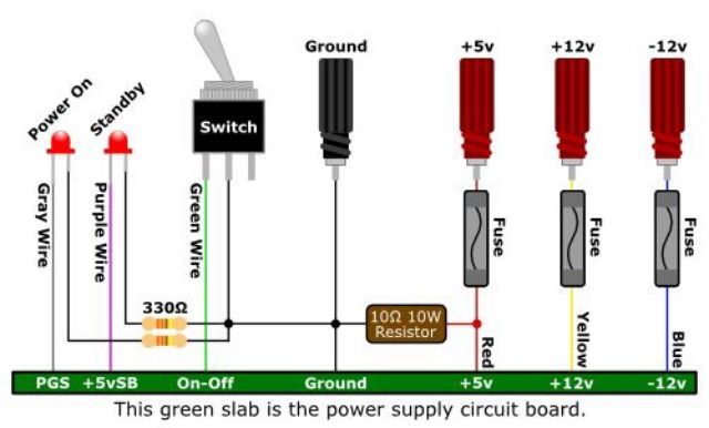
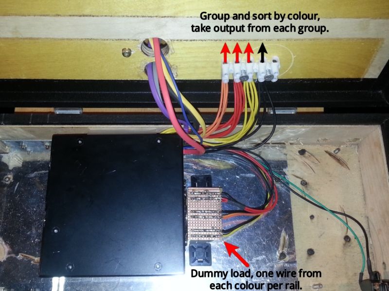
This is a WIP shot of my setup which shows the wire and load arrangements:
Good luck in your endeavour.
Thanks mate. I tried that but it didn't work. The next step is to unfortunately cut off the plugs and electrically connect all common coloured wires together to see if that makes a difference. I wanted to avoid that so I could use the "magic box" on any PSU.
Just see if all the wires of the same color have no resistance between them, no sense in chopping them.
Just see if all the wires of the same color have no resistance between them, no sense in chopping them.
I already tried that, all of the wires of the same colour had zero resistance as you'd expect. But then again so did some of different colours. So essentially it wasn't conclusive and therefore unhelpful.
Besides I've already clipped the wires and crimped them together. I need to test if this new configuration makes any difference.
Did you get it working in the end? As I'm acquiring similar results and nothing seems to be working...

