-
A serial connection is always a big problem
You need to keep it simple.
Drop Python Script: and use a simple terminal program.
If you can not easy type it on keyboard, do not send over serial.
No control codes except CR(13) and LF(10)
Get fancy later, now is time to keep is simple.
You have to get the types correct
You are wanting to read and write BYTES of data to a memory chip.
This is not a character!
Intel Hex was created for a reason, part is the working around serial port problems.
How can the Arduino check for data errors?
What you are writing is getting messed up with what you are reading.
void writebyte(byte byteValue)
Byte readbyte()
You really need this later and should do it now to help find the problems.
-
That I hadn't thought of. I guess my thinking is that current_character is reset when I call for the next byte from the serial buffer. Is that not how this works?
current_char is a global variable in your application, so you assigned it a value in Write():Code: [Select]current_character = Serial.read();
but then when you use it in Read() it will still contain that value it read from the pi which was 0xff. So you are effectively adding 0xFF to whatever you read from the data bus.Code: [Select]current_character = current_character + (digitalRead(Data_BUS[Data_Pin]) << Data_Pin);
global state is generally frowned upon, as it leads to these kind of side-effect bugs which are a pita to track down. In this Read() case you'd use a variable that was local to the functions, and wouldn't even access current_char:
// Reading Data
char dataRead = 0;
for(int Data_Pin = 0; Data_Pin < 8; Data_Pin++){
dataRead = dataRead + (digitalRead(Data_BUS[Data_Pin]) << Data_Pin);
}
-
Need a function
Void Address_to_595(int Memory_Address)
This function should do everything needed by the 595's to get "Memory_Address" on outputs of 595's
void writebyte(byte byteValue)
Byte readbyte()
The address is at the memory chip's address pins.
Do every thing else needed by memory chip.
Should take care of Arduino data buss direction and change it if needed.
Test and actual program will use these three functions.
-
Quote
Need a function
Void Address_to_595(int Memory_Address)
This function should do everything needed by the 595's to get "Memory_Address" on outputs of 595's
void writebyte(byte byteValue)
Byte readbyte()
The address is at the memory chip's address pins.
Do every thing else needed by memory chip.
Should take care of Arduino data buss direction and change it if needed.
Test and actual program will use these three functions.
This is kind of what I attempted to do with the current code, the functions definitely need revising, but I feel like they are getting there. I may have made a bit of a break through, I'm not sure. If I have got the declaration of local variables correct as rich suggested, and they are cleared each time a function ends, then I may be getting closer to finding the problem. I modified the code to cut out all the Serial garbage, as well as changed the variables to type byte. For testing purposes I have set the byte current_character to a constant value of 01000110 (which is 'F' in ASCII). I've also essentially tried to force the code into the writing part of the program. Thus the program should read what's in the current address, write to the address and then read it again to see if it's changed (as C suggested previously). If my declaration and understanding of local variables is correct, then the system is writing and reading this value correctly.
Here's the code:Code: [Select]/* This is the source file for the EPROM Programmer! The pin declarations in this file are specifically setup
* for the Arduino Micro, however you can modify the pins to fit your own Arduino Board. This code is paired with a python
* script that sends the hex file byte by byte to the Arduino, which will then put it into the correct address of the memory
*
* The hardware for this programmer is two 74HC595 Shift Registers driving the address BUS, with the data BUS and control
* pins directly connected to the Arduino Digital IO
*
* For more information please visit my website at: [url=http://www.RCtalesofarookie.weebly.com]www.RCtalesofarookie.weebly.com[/url]
*
* Created by Sam Maxwell
* FEB 2016
*/
// Constant Variables that hold pin assignments, please change these for your specific Ardunio Board
// Variables for the 74HC595 Shift Registers, used to drive the address BUS
const int Serial_Clock = 12;
const int Register_Clock = 10;
const int register_output_enable = 11;
const int Serial_Output = 9;
// Variables for the Memory Control Pins
const int memory_write_enable = 0;
const int memory_chip_enable = 1;
const int memory_output_enable = 14;
// Variables for the Data BUS
int Data_BUS[] = {2, 3, 4, 5, 6, 7, 8, 13};
// Variables for storing the current character and the current address
int current_address = 0;
// Main Code
// Setup
void setup(){
// Beginning Serial Communication with PC, used for communication with Python Script, as well as for debugging
Serial.begin(9600); // Serial at 9600 Baud
// Assigning Pin Modes that remain constant regardless of the function
// Shift Register Pin Modes
pinMode(Serial_Clock, OUTPUT);
pinMode(Register_Clock, OUTPUT);
pinMode(register_output_enable, OUTPUT);
pinMode(Serial_Output, OUTPUT);
// Memory Control Pin Modes
pinMode(memory_write_enable, OUTPUT);
pinMode(memory_chip_enable, OUTPUT);
pinMode(memory_output_enable, OUTPUT);
// IMPORTANT!!! Pin Mode assignments for the data BUS occur during the Read and Write functions as pin modes change depending on the function being used
// Making sure pins are at correct levels before cycles begin
// Shift Registers
digitalWrite(register_output_enable, HIGH);
// Memory Control Pin Levels
digitalWrite(memory_write_enable, HIGH);
digitalWrite(memory_chip_enable, HIGH);
digitalWrite(memory_output_enable, HIGH);
}
void loop(){
// Setting Local Variables
byte current_character = Serial.read();
String current_mode = "Write";
// Executing the corresponding function
if(current_mode == "Write"){
current_address = 0;
while(current_address < 35000){ // Python Script Prints } if the end of the file has been reached
if(Serial.available() > 0){
Increment_Address();
Serial.print("");
Read();
Serial.print("");
Write();
Serial.print("");
Read();
Serial.println("");
}
}
}
if(current_mode == "Read"){
current_address = 0;
while(current_address < 35000){
Increment_Address();
Read(); // Executing the Read Function if current_mode == Read
}
}
}
void Write(){
  // Write Cycle
  // Declaring Local Variables
  byte current_character = 01000111;
// Setting Data BUS Pin Modes to OUTPUT for Writing
for(int Data_Pin = 0; Data_Pin < 8; Data_Pin++){
pinMode(Data_BUS[Data_Pin], OUTPUT);
}
// Setting Data Bus Values
for(int Data_Pin = 0; Data_Pin < 8; Data_Pin++){
digitalWrite(Data_BUS[Data_Pin], bitRead(current_character, Data_Pin));
}
// Setting Memory Control Pins
digitalWrite(memory_output_enable, HIGH);
digitalWrite(memory_chip_enable, LOW);
digitalWrite(memory_write_enable, LOW);
// Sending character that is going to be written over serial port for python script
Serial.print("Current Character: ");
Serial.print(current_character);
// Delay to allow Data to become valid
delay(2);
// Setting Memory Control Pins
digitalWrite(memory_write_enable, HIGH);
digitalWrite(memory_chip_enable, HIGH);
}
void Read(){
// Read Cycle
// Declaring Local Variables
byte current_character;
byte current_string;
// Setting Data BUS Pin Modes to INPUT for Reading
for(int Data_Pin = 0; Data_Pin < 8; Data_Pin++){
pinMode(Data_BUS[Data_Pin], INPUT);
}
// Setting Memory Control Pins
digitalWrite(memory_write_enable, HIGH);
digitalWrite(memory_chip_enable, LOW);
digitalWrite(memory_output_enable, LOW);
// Delay to allow Data to become valid
delay(2);
// Reading Data
for(int Data_Pin = 0; Data_Pin < 8; Data_Pin++){
current_character = (digitalRead(Data_BUS[Data_Pin]) << Data_Pin);
current_string += current_character;
}
// Setting Memory Control Pins
digitalWrite(memory_output_enable, HIGH);
digitalWrite(memory_chip_enable, HIGH);
// Printing current character over the serial port for the python script
Serial.print("Current String");
Serial.print(current_string);
}
void Increment_Address(){
// Setting Shift Register Control Pins
digitalWrite(register_output_enable, HIGH);
digitalWrite(Register_Clock, LOW);
// Shifting Out Current Address Value
// Shifting Out High Byte
shiftOut(Serial_Output, Serial_Clock, MSBFIRST, highByte(current_address));
// Shifting Out Low Byte
shiftOut(Serial_Output, Serial_Clock, MSBFIRST, lowByte(current_address));
// Setting Shift Register Control Pins
digitalWrite(Register_Clock, HIGH);
digitalWrite(register_output_enable, LOW);
// Incrementing the value of current_address by one
current_address = current_address + 1;
Serial.print("Current Address");
Serial.print(current_address);
}
And here's the output it's giving: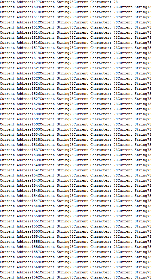
And here's my extremely crude schematic again just for good measure: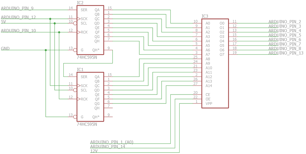
For Some Reason it's off by two always. And it's reading a value of 72 on the first read cycle on every address value but 0. This makes me think that the I still don't get the idea of local declaration of variables.
Tomorrow I am going to strip it right back to the bare minimum. I will put LED's on the data and address BUS and write some code that literally forces one input at one address. I'll then see it I get the right value back. Nothing fancy. Hopefully I shall come back with some good news. -
The local variables you have allocated inside of Read() need initialising before using them otherwise they contain whatever garbage is on the stack when the function is entered. I should've highlighted this subtle difference between local and global variables in C although my example code did set it to zero before using it!
I would suggest you always initialise every variable (local and global) where you declare them. This forces you to think about what the initial value should be, helps anyone else reading your code and avoids getting caught out by the language/compiler.
So onto your Read() function: You only need one local variable in Read() not two. Get rid of current_string and use the previous code I posted for your loop, but make sure you initialise the variable to zero before trying to add number to it for the first time. -
Just had another look at your code. You said you were setting 'F' as the character to write. But declared current_character as follows.Code: [Select]
void Write(){
// Write Cycle
// Declaring Local Variables
byte current_character = 01000111;
Now, Binary 01000111 corresponds to ASCII 'G'. Unfortunately for your program the C compiler will interpret 01000111 in Octal which happens to be ASCII 'I'. Maybe that is a source of some of the confusion. -
Go to link and read
https://www.arduino.cc/en/Reference/FunctionDeclaration
https://www.arduino.cc/en/Reference/IntegerConstants
Now fix your functions, and save some time.
Shorten up your prints so actual information is easer to read. A binary output is better choice here I think.
A: 1010101010101010 R: 01010101 W: 11110000 R: 11100100
With proper functions the following gets passed to function
byte current_character = 01000111;
errrrr NO characters here memory_byte or current_byte or _____________
doing the following
Address_to_595(1000)
byte_before = readbyte()
writebyte(B01000111)
byte_after = readbyte()
Address_to_595(1050)
writebyte(B01010111)
Address_to_595(1000)
byte_check = readbyte()
Address_to_595(1050)
byte_check1 = readbyte()
after that
byte_after == byte_check == B01000111
byte_check1 == B01010111
With the functions being passed the data or returning the data, arrays are easy to use.
Edit
Is this program a one shot thing?
Parts of it could be used many places.
The 74HC595's can give a 16-bit tri-state output by using pin 13. These could be connected to your Z80's address buss and used when the Z80's address bus is in tri-state mode. Hint ( /RESET or doing /BUSREQ and getting /BUSACK )Code: [Select]// Variables for the Data BUSWith functions a bidirectional data buss. More Arduino pins could be like this.
int Data_BUS[] = {2, 3, 4, 5, 6, 7, 8, 13};
The above two parts can be used many places.
Not far from hardware for Z80 DMA or Z80 reset boot loader.
With a little work "Data_BUS[]" above could have the software using this array adjust for different number of pins in array.
Could have two arrays "Setup_Input_Pins[]" & "Setup_Output_Pins[]" for the setup function to use with pinMode.
I think it is worth the time to get the software right and at same time simple and readable. Understanding how it works is a big plus.
This will save time now and in the future.
So keep software simple and get software working correctly. When software is working, only then slowly make changes and test the changes to see if software still works.
-
Ok, as I said I have gone back to basics. I have hooked up some LED's to the address BUS just to test that the code that increments the current address and puts it on the BUS is functioning correctly. The BUS counts up through the addresses correctly and the output is stable, so this part of the code is definitely working. Here's the code:Code: [Select]
/* This is the source file for the EPROM Programmer! The pin declarations in this file are specifically setup
* for the Arduino Micro, however you can modify the pins to fit your own Arduino Board. This code is paired with a python
* script that sends the hex file byte by byte to the Arduino, which will then put it into the correct address of the memory
*
* The hardware for this programmer is two 74HC595 Shift Registers driving the address BUS, with the data BUS and control
* pins directly connected to the Arduino Digital IO
*
* For more information please visit my website at: [url=http://www.RCtalesofarookie.weebly.com]www.RCtalesofarookie.weebly.com[/url]
*
* Created by Sam Maxwell
* FEB 2016
*/
// Constant Variables that hold pin assignments, please change these for your specific Ardunio Board
// Variables for the 74HC595 Shift Registers, used to drive the address BUS
const int Serial_Clock = 12;
const int Register_Clock = 10;
const int register_output_enable = 11;
const int Serial_Output = 9;
// Variables for the Memory Control Pins
const int memory_write_enable = 0;
const int memory_chip_enable = 1;
const int memory_output_enable = 14;
// Variables for the Data BUS
int Data_BUS[] = {2, 3, 4, 5, 6, 7, 8, 13};
// Variables for storing the current character and the current address
int current_address = 0;
// Main Code
// Setup
void setup(){
// Beginning Serial Communication with PC, used for outputting what the system is doing.
Serial.begin(9600);
// Assigning Pin Modes that remain constant regardless of the function
// Shift Register Pin Modes
pinMode(Serial_Clock, OUTPUT);
pinMode(Register_Clock, OUTPUT);
pinMode(register_output_enable, OUTPUT);
pinMode(Serial_Output, OUTPUT);
// Memory Control Pin Modes
pinMode(memory_write_enable, OUTPUT);
pinMode(memory_chip_enable, OUTPUT);
pinMode(memory_output_enable, OUTPUT);
// Making sure pins are at correct levels before cycles begin
// Shift Registers
digitalWrite(register_output_enable, HIGH);
// Memory Control Pin Levels
digitalWrite(memory_write_enable, HIGH);
digitalWrite(memory_chip_enable, HIGH);
digitalWrite(memory_output_enable, HIGH);
}
void loop(){
// Setting Shift Register Control Pins
digitalWrite(register_output_enable, HIGH);
digitalWrite(Register_Clock, LOW);
// Shifting Out Current Address Value
// Shifting Out High Byte
shiftOut(Serial_Output, Serial_Clock, MSBFIRST, highByte(current_address));
// Shifting Out Low Byte
shiftOut(Serial_Output, Serial_Clock, MSBFIRST, lowByte(current_address));
// Setting Shift Register Control Pins
digitalWrite(Register_Clock, HIGH);
digitalWrite(register_output_enable, LOW);
// Incrementing the value of current_address by one
Serial.print("Current Address: ");
Serial.println(current_address);
current_address = current_address + 1;
// Delay
delay(100);
}
Time to put this code into it's own function and then test out the data BUS. Something really important has just occurred to me though. In the old code I never reset the value of current_address to 0. So when I went for a read function after writing to the system, it would be completely the wrong address. This still doesn't solve the problem, as I did a read cycle during the writing function, but it's still super important. Need to sort that out in this code. -
I've now also confirmed that the code used to write the data onto the data BUS is working. Here's the code: (Bare in mind that the Increment_Address Function is essentially commented out).Code: [Select]
/* This is the source file for the EPROM Programmer! The pin declarations in this file are specifically setup
 *  for the Arduino Micro, however you can modify the pins to fit your own Arduino Board. This code is paired with a python
 *  script that sends the hex file byte by byte to the Arduino, which will then put it into the correct address of the memory
 *
 *  The hardware for this programmer is two 74HC595 Shift Registers driving the address BUS, with the data BUS and control
 *  pins directly connected to the Arduino Digital IO
 *
 *  For more information please visit my website at: [url=http://www.RCtalesofarookie.weebly.com]www.RCtalesofarookie.weebly.com[/url]
 *
 *  Created by Sam Maxwell
 *  FEB 2016
 */

// Constant Variables that hold pin assignments, please change these for your specific Ardunio Board
// Variables for the 74HC595 Shift Registers, used to drive the address BUS
const int Serial_Clock = 12;
const int Register_Clock = 10;
const int register_output_enable = 11;
const int Serial_Output = 9;

// Variables for the Memory Control Pins
const int memory_write_enable = 0;
const int memory_chip_enable = 1;
const int memory_output_enable = 14;

// Variables for the Data BUS
int Data_BUS[] = {2, 3, 4, 5, 6, 7, 8, 13};

// Variables for storing the current character and the current address
int current_address = 0;
char current_character = '0';

// Main Code
// Setup
void setup(){
  // Beginning Serial Communication with PC, used for outputting what the system is doing.
  Serial.begin(9600);

  // Assigning Pin Modes that remain constant regardless of the function
  // Shift Register Pin Modes
  pinMode(Serial_Clock, OUTPUT);
  pinMode(Register_Clock, OUTPUT);
  pinMode(register_output_enable, OUTPUT);
  pinMode(Serial_Output, OUTPUT);

  // Memory Control Pin Modes
  pinMode(memory_write_enable, OUTPUT);
  pinMode(memory_chip_enable, OUTPUT);
  pinMode(memory_output_enable, OUTPUT);

  // Making sure pins are at correct levels before cycles begin
  // Shift Registers
  digitalWrite(register_output_enable, HIGH);

  // Memory Control Pin Levels
  digitalWrite(memory_write_enable, HIGH);
  digitalWrite(memory_chip_enable, HIGH);
  digitalWrite(memory_output_enable, HIGH);

  // Setting Data BUS Pin Modes to OUTPUT for Writing
  for(int Data_Pin = 0; Data_Pin < 8; Data_Pin++){
    pinMode(Data_BUS[Data_Pin], OUTPUT);
  }
}

void loop(){

}

void Increment_Address(){
  // Setting Shift Register Control Pins
  digitalWrite(register_output_enable, HIGH);
  digitalWrite(Register_Clock, LOW);

  // Shifting Out Current Address Value
  // Shifting Out High Byte
  shiftOut(Serial_Output, Serial_Clock, MSBFIRST, highByte(current_address));
  // Shifting Out Low Byte
  shiftOut(Serial_Output, Serial_Clock, MSBFIRST, lowByte(current_address));

  // Setting Shift Register Control Pins
  digitalWrite(Register_Clock, HIGH);
  digitalWrite(register_output_enable, LOW);

  // Incrementing the value of current_address by one
  Serial.print("Current Address: ");
  Serial.println(current_address);
  current_address = current_address + 1;

  // Delay
  delay(100);
}

void Write(){
  // Writing the Current Character onto the Data Bus
  for(int Data_Pin = 0; Data_Pin < 8; Data_Pin++){
    digitalWrite(Data_BUS[Data_Pin], bitRead(current_character, Data_Pin));
  }
}
I'm now going to hook up the first eight bits of the address BUS to the Data Bus and see if the system is reading the data correctly and giving the right value. -
In the setup function CALL three functions
void Init_Address_Buss()
void Init_Data_Buss()
void Init_Control_Buss()
That is three simple functions where you are doing a cut & paste.
The other functions have been listed, A blank function with proper name and again a cut & paste to move code.
A simple step one.
Step two read what you have pasted.
If information from function goes out of function for other code to use, it is not a void function, but a function with a type and you need to make internal to function data be returned properly.
In most cases I have spent more time typing here then you would need to make the change!
edit Change in black above -
I don't understand what you mean by having a function for the address BUS and the data BUS. For the control BUS is it wise to have a function because it needs to be set to different values depending on whether you are reading or writing?Quote
doing the following
Address_to_595(1000)
byte_before = readbyte()
writebyte(B01000111)
byte_after = readbyte()
Address_to_595(1050)
writebyte(B01010111)
Address_to_595(1000)
byte_check = readbyte()
Address_to_595(1050)
byte_check1 = readbyte()
after that
byte_after == byte_check == B01000111
byte_check1 == B01010111
With the functions being passed the data or returning the data, arrays are easy to use.
I'm following what you said here ^^^^^^, seems to make more sense as a setup to me. But then I'm not as experienced at this.
I've verified the read function by connecting up the data BUS to the address BUS, it's reading the correct value in, so all seems good. I'm going to put this stuff into it's own function and then set then put in the code for the memory control pins. Time to see if I can actually write something into memory and then read it out again. -
Address_to_595(1000)
is a call to a function with a header like this
void Address_to_595(int AddressValue)
simple function that just takes AddressValue and gets it on the outputs of the 595's
others are more of the same idea with some returning data from function.
-
Note the change before your last post
You have been using functions that have been written by others.
You need to write a lot of very simple functions. Simple makes it easer to read and reduces area for problems.
right now you are dealing with a hardware interface.
Three separate interfaces that need to work together to do what is needed.
Address buss
Data buss
Control buss
The simple functions are called from higher level functions to do the job.
-
Quote
Time to see if I can actually write something into memory and then read it out again.
This is one place where you are going wrong.
Get the low level functions working properly.
Then when adding the to/from memory part, you are actually doing more testing of low level functions. If the low level functions are correct then the errors must be in function calling lower level functions.
-
Code: [Select]
boolean Simple_Test(){

Address_to_595(1000)
byte_before = readbyte()
writebyte(B01000111)
byte_after = readbyte()
Address_to_595(1050)
writebyte(B01010111)
Address_to_595(1000)
byte_check = readbyte()
Address_to_595(1050)
byte_check1 = readbyte()
}
Fix up the above function and you have a partial test of low level functions
-
Well, they say 3rd times the charm, and I think it might be in this case. I think it's working!

I've rewritten and tested the code in chunks, I just completed a test of the full code with the memory, and it's returning the right values! I'd like you guys to check before I proceed any further, but this seems like it's working to me! Here's the code:Code: [Select]/* This is the source file for the EPROM Programmer! The pin declarations in this file are specifically setup
* for the Arduino Micro, however you can modify the pins to fit your own Arduino Board. This code is paired with a python
* script that sends the hex file byte by byte to the Arduino, which will then put it into the correct address of the memory
*
* The hardware for this programmer is two 74HC595 Shift Registers driving the address BUS, with the data BUS and control
* pins directly connected to the Arduino Digital IO
*
* For more information please visit my website at: [url=http://www.RCtalesofarookie.weebly.com]www.RCtalesofarookie.weebly.com[/url]
*
* Created by Sam Maxwell
* FEB 2016
*/
// Constant Variables that hold pin assignments, please change these for your specific Ardunio Board
// Variables for the 74HC595 Shift Registers, used to drive the address BUS
const int Serial_Clock = 12;
const int Register_Clock = 10;
const int register_output_enable = 11;
const int Serial_Output = 9;
// Variables for the Memory Control Pins
const int memory_write_enable = A0;
const int memory_chip_enable = A1;
const int memory_output_enable = A2;
int Read_Write; // Read Cycle = 0, Write Cycle = 1
// Variables for the Data BUS
int Data_BUS[] = {2, 3, 4, 5, 6, 7, 8, 13};
// Variables for storing the ROM File and the current address
int current_address = 0;
int ROM_Array[] = {0x3B, 0x3C, 0x3A, 0x3B, 0x3D};
// Main Code
// Setup
void setup(){
// Beginning Serial Communication with PC, used for outputting what the system is doing.
Serial.begin(9600);
// Assigning Pin Modes that remain constant regardless of the function
// Shift Register Pin Modes
pinMode(Serial_Clock, OUTPUT);
pinMode(Register_Clock, OUTPUT);
pinMode(register_output_enable, OUTPUT);
pinMode(Serial_Output, OUTPUT);
// Memory Control Pin Modes
pinMode(memory_write_enable, OUTPUT);
pinMode(memory_chip_enable, OUTPUT);
pinMode(memory_output_enable, OUTPUT);
// Making sure pins are at correct levels before cycles begin
// Shift Registers
digitalWrite(register_output_enable, HIGH);
// Memory Control Pin Levels
digitalWrite(memory_write_enable, HIGH);
digitalWrite(memory_chip_enable, HIGH);
digitalWrite(memory_output_enable, HIGH);
}
void loop(){
Read();
delay(2000);
Serial.print(" ");
Write();
delay(2000);
Serial.print(" ");
Read();
delay(2000);
Serial.print(" ");
Increment_Address();
if(current_address > 33000){
Serial.println("Memory Programmed!");
Serial.println("Please Verify that the program is correct!");
while(1){
}
}
}
void Increment_Address(){
// Setting Memory Controls
digitalWrite(memory_chip_enable, HIGH);
// Setting Shift Register Control Pins
digitalWrite(register_output_enable, HIGH);
digitalWrite(Register_Clock, LOW);
// Shifting Out Current Address Value
// Shifting Out High Byte
shiftOut(Serial_Output, Serial_Clock, MSBFIRST, highByte(current_address));
// Shifting Out Low Byte
shiftOut(Serial_Output, Serial_Clock, MSBFIRST, lowByte(current_address));
// Setting Shift Register Control Pins
digitalWrite(Register_Clock, HIGH);
digitalWrite(register_output_enable, LOW);
// Incrementing the value of current_address by one
Serial.print("A: ");
Serial.println(current_address);
current_address = current_address + 1;
// Delay
delay(2);
}
void Write(){
// Setting Data BUS Pin Modes to OUTPUT for Writing
for(int Data_Pin = 0; Data_Pin < 8; Data_Pin++){
pinMode(Data_BUS[Data_Pin], OUTPUT);
}
// Setting Current Character
int current_byte = ROM_Array[current_address];
// Sending Data to Serial Terminal
Serial.print("W: ");
Serial.print(current_byte);
// Writing the Current Character onto the Data Bus
for(int Data_Pin = 0; Data_Pin < 8; Data_Pin++){
digitalWrite(Data_BUS[Data_Pin], bitRead(current_byte, Data_Pin));
}
// Setting Memory Control Pins
Read_Write = 1;
Memory_Control();
// Delay
delay(2);
// Setting Memory Control Pins
digitalWrite(memory_chip_enable, HIGH);
digitalWrite(memory_write_enable, HIGH);
digitalWrite(memory_output_enable, HIGH);
}
void Read(){
// Setting Data BUS Pin Modes to INPUT for Reading
for(int Data_Pin = 0; Data_Pin < 8; Data_Pin++){
pinMode(Data_BUS[Data_Pin], INPUT);
}
// Resetting Current String
int current_byte = 0;
// Setting Memory Control Pins
Read_Write = 0;
Memory_Control();
// Delay
delay(2);
// Reading Data
for(int Data_Pin = 0; Data_Pin < 8; Data_Pin++){
int current_bit = (digitalRead(Data_BUS[Data_Pin]) << Data_Pin);
current_byte += current_bit;
}
// Setting Memory Control Pins
digitalWrite(memory_chip_enable, HIGH);
digitalWrite(memory_output_enable, HIGH);
// Sending Data to Serial Terminal
Serial.print("R: ");
Serial.print(current_byte);
}
void Memory_Control(){
// If we are in a Read Cycle
if(Read_Write == 0){
digitalWrite(memory_write_enable, HIGH);
digitalWrite(memory_chip_enable, LOW);
digitalWrite(memory_output_enable, LOW);
}
// If we are in a Write Cycle
if(Read_Write == 1){
digitalWrite(memory_output_enable, HIGH);
digitalWrite(memory_chip_enable, LOW);
digitalWrite(memory_write_enable, LOW);
}
}
And here's an image of the output it's giving: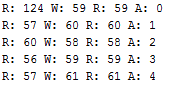
That awesome feeling of success! Can't thank you enough for your help guys! I just need to modify the control pins for the EPROM's, and then I'm good too go I think. After I have typed the whole of the ROM file into the ROM_Array[] that is.
Thanks again! -
It's come a long way since your first code. You should be proud of the progress

There are a few more refactors you shoud make though. C has said this before, but I'll phrase it differnetly for you:
You need to move beyound treating functions as just a grouping of statements and exploit the fact they can be passed data and return data.
One of the issues you have created for yourself by not passing data to/from your functions is that you are forced to mix your global application state mutations (e.g. incrementing address and reading serial ports) inside of what should be primitive functions that somebody else could easily use as a bias for their application without unexpected side-effects.
Go back and read the thread again with your newfound skills - the type of functions have already been suggested multiple times.
-
Ok, that makes more sense. Apologies to C who has said it multiple times, it's just taken me a bit of time to understand what your trying to tell me.
-
I'm full of mistakes! The system is still working as far as I can tell, but I forgot that I had moved some of the jumper leads from the data BUS to the data pins on the memory. When I was looking at the data that was coming back from the system before I remedied my mistake, I was seeing rare occurrences where the data would be wrong, but it would be write for the same value one cycle later. Having moved the jumper leads back to the correct place the system is working very reliably.
My question is, how was the data coming through when I had the jumper leads one row off on every data line. What I've learnt in physics tells me it's either something to do with the magnetic fields induced in around the tracks, although they would be very small. Or some kind of capacitance?
-
Thanks rich
This may work, but you are not seeing the big picture.QuoteThat awesome feeling of success! Can't thank you enough for your help guys! I just need to modify the control pins for the EPROM's, and then I'm good too go I think. After I have typed the whole of the ROM file into the ROM_Array[] that is.
You typing or translating that rom image in Intel Hex format is going to allow more errors. Is a big waist of time also and would have to be done again for a new rom image.
If you treat the Arduino as a dumb device, just three simple commands are needed for a program on the PC to read the Intel Hex rom image and talk to the Arduino and program the chip. Not great way to do this but can be faster then you adding errors with translation.
Pc just needs to be able to,
1. Tell the Arduino the address.
2. Tell the Arduino what byte value to write.
3. Ask the Arduino what is the byte value.
You are making it harder on you self getting the job done.
You have made progress in programming but not seeing big picture again.
There are many reasons to use the Intel Hex format directly on the Arduino. You can get the above and then add this step with out much loss of time. Do it right and things grow real easy.
Questions
In how many other programs on Arduino could you have a use for a few Arduino pins giving you more output by using a 595? And just by adding an additional 595 on hardware side get 8 more bits of output?
Using good functions here, passing data to and from the functions will let this become an easy copy and paste. It also helps this program!
Your program gets simple and easy to read. It also allows easy additions.
So think big
Most programming tools for the Z80 create Intel Hex format files. Easy way to use of these files makes your life easer.
If You hold the Z80 with the /RESET line low, think you will find that the Z80 Address, Data & Control lines are in the tri-state mode.
The 595's have a tri-state output.
What you are using on Arduino for data & control buss can be set as inputs. To Z80 this is same as tri-state.
The Arduino using a pin connected the Z80 /RESET pin could make the /RESET pin go low. The Z80 then tri-states as above.
The Arduino could then enable it's outputs and program Z80 memory.
When done the Arduino makes all outputs tri-state or inputs and releases the Z80 /reset pin.
You have just started the Z80 with a new program that can easily be changed. A great way to learn the Z80 with out having to program and erase proms.
The kicker is that this can also read Z80 memory.
A small addition and Arduino can read & write Z80 memory while the Z80 is running a program!!
Many people giving you hints.
Think of the iceburg, most is under water while the hints point to what you can see.I'm full of mistakes! The system is still working as far as I can tell, but I forgot that I had moved some of the jumper leads from the data BUS to the data pins on the memory. When I was looking at the data that was coming back from the system before I remedied my mistake, I was seeing rare occurrences where the data would be wrong, but it would be write for the same value one cycle later. Having moved the jumper leads back to the correct place the system is working very reliably.
My question is, how was the data coming through when I had the jumper leads one row off on every data line. What I've learnt in physics tells me it's either something to do with the magnetic fields induced in around the tracks, although they would be very small. Or some kind of capacitance?
bad programming or the ram chip not caring.
A scrambled address buss in to ram works fine.
A scrambled data buss in to ram works fine.
-
Hmm ok, however long it's taken me, I am cottoning on to the point you are making. It took me a while, but I understand what you mean about looking at the bigger picture. Less hardware specific functions can be used in all sorts of code, as you say if I ever need a 595, I can use code that I have previously written. This makes a world of sense. Also I never really thought about the Arduino being an active part of the system in terms of programming memory, acting as a sort of boot loader. What's great about this is that the Arduino can also be used to access more modern devices on the I2C and SPI BUS, as you were explaining to me in my other post.
I'm starting to see what's below the surface, just takes a while to understand the basics of your surroundings. This computer build has been a great learning process so far and will continue to be, a few months ago I didn't understand anything about the internal workings of processors, memory, etc. Now I understand how the basic system works, and what it's actually doing. It definitely gives me a new found respect for what's happening inside my computers processor as I type this. -
The hardware will work properly when you have a good program and proper connections.
The Important thing now is to re-read this thread and fix proper functions.
When you have this, the remaining parts can be done fast and easy.
-
Remove the serial prints from your last code post and put them in separate functions.
-
Ok, so I tried to program one of my OTPROM's before I modify the code more. I've got something working so I am inclined to get one programmed ROM so that I can test the rest of the build. I will being going back and making the changes you have suggested however.
Now I don't know whether its an issue with the read cycle of the system, or something worse. But the data I am getting back is extremely weird. There are repeating patterns, nothing like what the code is supposed to look like. I fed 12 volts into the VPP pin as the datasheet suggested, and made sure the control pins were correct for the OTPROM chips and not the SRAM. So I don't know what's wrong. I added a capacitor from VPP to ground as the datasheet also suggested.
Here's the output of the file: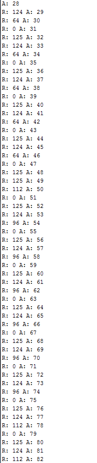
And here's the modified code:Code: [Select]/* This is the source file for the EPROM Programmer! The pin declarations in this file are specifically setup
* for the Arduino Micro, however you can modify the pins to fit your own Arduino Board. This code is paired with a python
* script that sends the hex file byte by byte to the Arduino, which will then put it into the correct address of the memory
*
* The hardware for this programmer is two 74HC595 Shift Registers driving the address BUS, with the data BUS and control
* pins directly connected to the Arduino Digital IO
*
* For more information please visit my website at: [url=http://www.RCtalesofarookie.weebly.com]www.RCtalesofarookie.weebly.com[/url]
*
* Created by Sam Maxwell
* FEB 2016
*/
// Constant Variables that hold pin assignments, please change these for your specific Ardunio Board
// Variables for the 74HC595 Shift Registers, used to drive the address BUS
const int Serial_Clock = 12;
const int Register_Clock = 10;
const int register_output_enable = 11;
const int Serial_Output = 9;
// Variables for the Memory Control Pins
const int memory_chip_enable = A1;
const int memory_output_enable = A2;
int Read_Write; // Read Cycle = 0, Write Cycle = 1
// Variables for the Data BUS
int Data_BUS[] = {2, 3, 4, 5, 6, 7, 8, 13};
// Variables for storing the ROM File and the current address
int current_address = 0;
// Main Code
// Setup
void setup(){
// Beginning Serial Communication with PC, used for outputting what the system is doing.
Serial.begin(9600);
// Assigning Pin Modes that remain constant regardless of the function
// Shift Register Pin Modes
pinMode(Serial_Clock, OUTPUT);
pinMode(Register_Clock, OUTPUT);
pinMode(register_output_enable, OUTPUT);
pinMode(Serial_Output, OUTPUT);
// Memory Control Pin Modes
pinMode(memory_chip_enable, OUTPUT);
pinMode(memory_output_enable, OUTPUT);
// Making sure pins are at correct levels before cycles begin
// Shift Registers
digitalWrite(register_output_enable, HIGH);
// Memory Control Pin Levels
digitalWrite(memory_chip_enable, HIGH);
digitalWrite(memory_output_enable, HIGH);
}
void loop(){
Read();
delay(10);
Serial.print(" ");
delay(100);
Increment_Address();
if(current_address > 33000){
Serial.println("Memory Programmed!");
Serial.println("Please Verify that the program is correct!");
while(1){
}
}
}
void Increment_Address(){
// Setting Memory Controls
digitalWrite(memory_chip_enable, HIGH);
// Setting Shift Register Control Pins
digitalWrite(register_output_enable, HIGH);
digitalWrite(Register_Clock, LOW);
// Shifting Out Current Address Value
// Shifting Out High Byte
shiftOut(Serial_Output, Serial_Clock, MSBFIRST, highByte(current_address));
// Shifting Out Low Byte
shiftOut(Serial_Output, Serial_Clock, MSBFIRST, lowByte(current_address));
// Setting Shift Register Control Pins
digitalWrite(Register_Clock, HIGH);
digitalWrite(register_output_enable, LOW);
// Incrementing the value of current_address by one
Serial.print("A: ");
Serial.println(current_address);
current_address = current_address + 1;
// Delay
delay(2);
}
void Write(){
// Setting Data BUS Pin Modes to OUTPUT for Writing
for(int Data_Pin = 0; Data_Pin < 8; Data_Pin++){
pinMode(Data_BUS[Data_Pin], OUTPUT);
}
// Setting Current Character
char current_byte = Serial.read();
// Sending Data to Serial Terminal
Serial.print("W: ");
Serial.print(current_byte);
// Writing the Current Character onto the Data Bus
for(int Data_Pin = 0; Data_Pin < 8; Data_Pin++){
digitalWrite(Data_BUS[Data_Pin], bitRead(current_byte, Data_Pin));
}
// Setting Memory Control Pins
Read_Write = 1;
Memory_Control();
// Delay
delay(2);
// Setting Memory Control Pins
digitalWrite(memory_chip_enable, HIGH);
digitalWrite(memory_output_enable, HIGH);
}
void Read(){
// Setting Data BUS Pin Modes to INPUT for Reading
for(int Data_Pin = 0; Data_Pin < 8; Data_Pin++){
pinMode(Data_BUS[Data_Pin], INPUT);
}
// Resetting Current String
int current_byte = 0;
// Setting Memory Control Pins
Read_Write = 0;
Memory_Control();
// Delay
delay(2);
// Reading Data
for(int Data_Pin = 0; Data_Pin < 8; Data_Pin++){
int current_bit = (digitalRead(Data_BUS[Data_Pin]) << Data_Pin);
current_byte += current_bit;
}
// Setting Memory Control Pins
digitalWrite(memory_chip_enable, HIGH);
digitalWrite(memory_output_enable, HIGH);
// Sending Data to Serial Terminal
Serial.print("R: ");
Serial.print(current_byte);
}
void Memory_Control(){
// If we are in a Read Cycle
if(Read_Write == 0){
digitalWrite(memory_chip_enable, HIGH);
digitalWrite(memory_output_enable, LOW);
}
// If we are in a Write Cycle
if(Read_Write == 1){
digitalWrite(memory_output_enable, HIGH);
digitalWrite(memory_chip_enable, LOW);
}
}
Thanks for all the help, hopefully there is a solution to this as well, I just can't wait to see my computer going for the first time!
-
wasting everyone's time again.