-
I want to measure the voltage from a 150 Vdc generator to Arduino.
The voltage will change from 0 - 150 Vdc.
What equipment should I use to separate the ground system?
-
Can you clarify the following?
1.) Do you want to measure between 0 and 150V using an an Arduino's ADC?
2.) Can you re-explain what you mean by: "What equipment should I use to separate the ground system?"
What's your application? -
Yes - a bit more detail would help here ... especially about why you ask this:
What equipment should I use to separate the ground system?
Do you have incompatible ground reference points? And if you do, we would need to know more about the situation to be able to comment intelligently. -
I want to measure the voltage from a 150 Vdc generator to Arduino.
Hi MISAKAREE
The voltage will change from 0 - 150 Vdc.
What equipment should I use to separate the ground system?
This is a common requirement where you have two systems with different 0V references (grounds) and you want to keep them separate.
You can do it with some fancy electronics, using an isolated communications interface, but the simplest way is with a swinging capacitor.
I will knock up a schematic to show how it works. -
If the circuits both share the same reference, then a potential divider is all that's required.
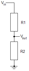
R1 = 180k or 1M8
R2 = 62k or 620k
Will give an output of 4.995V, with an input of 150V, an error of -0.1%.
Put a 10nF capacitor across R2 to provide a low impedance AC path for the MCU's sample and hold capacitor's charge to flow in/out of.
The component values were selected using the calculator linked below:
https://www.random-science-tools.com/electronics/divider.htm -
UPDATE #1 Although the principle illustrated is sound, the circuit below has a major error in the value for R1, which means a modification is required.
+ MISAKAREE
Attached below is the schematic for the swinging capacitor isolating circuit mentioned in reply#3:
This is how it works:
The relay, when de-energized, connects C1 across the voltage to be measured in the remote unit, so that C1 always has that voltage across its terminals.
When you want to read the voltage by the MCU, you energies the relay by setting the MCU output line to high.
Then do an input voltage read.
It is important to do the switching and reading as fast as possible, so that C1 does not loose too much of it's charge and thus give erroneous voltage readings.
Once the input read is complete, de-energies the relay so that C1 is once more connected to the 0V and 150V line of the remote unit.
C1 is a polypropylene capacitor, with a voltage rating of 180V or more. The absolute value of C1 is unimportant, as long as it is not much less than 100nF.
R1/R2 attenuation has a ratio of more or less 150V:5V, but it is not exact as I have used standard resistor values. You can change the attenuation to whatever you like, by changing the value of R2, but best to leave R1 as is. Alternatively, you can do any necessary corrections in software.
The circuit is pretty much functional, but decoupling capacitors are not shown. Note the usual warning that the NMOSFET gate stopper resistor must be mounted with short leads on the gate side and connected directly to the gate pin, or pretty near.
-
Good idea spec.
A resistor in series with the input would be a good idea to limit the charge current through C1 and prolong the life of the relay contacts: 220R to 2k2 would do.
I think you've got the the decimal point wrong when calculating R1 and R2. R1 = 10M and R2 = 330R will give 4.95mV, not 4.95V. Use the values in my previous post: R1 = 180k and R2 = 62k for 4.995V or you could go for 100k and 3k3 for 4.8V, which will provide some headroom.
A buffer amplifier might be required, as ADCs require a low impedance source to charge/discharge the sample and hold capacitor. With a plain potential divider, a capacitor can be connected across the ADC input and 0V, but this won't work for a switched capacitor, as it takes time for the voltage to stabilise.
The paper linked below describes the problem of using an ADC with a high impedance source:
http://www.ti.com/lit/an/spna061/spna061.pdf
Another thing to note is the level of isolation provided by most relay contacts is insufficient to protect against shock, only the coil is has adequate separation, but 150V isn't that higher voltage, so shouldn't by a safety hazard.
-
Looks like a good way to get the wrong answer to me!
If i was doing it that way, and i wouldn't, i'd put the divider on the HV side and switch the cap across to the ADC, that way its capacitance acts to charge the sample and hold capacitance of the ADC itself. With your system, you'll have to have the cap switched to the ADC side for long enough to ensure the smaple and hold capacitance is charger,which with a 10Meg resistor in line will be ages, and with the lower resistor in parallel with the ADC, that resistor will take the bulk of the current from the switching cap.......
i'd either:
1) run a low power micro straight off the 150vdc, and through a fixed resistive divider into the ADC, and then i'd stick the data out over an optoisolated serial link. That gives you your isolation, and no worries about messing around with caps and relays etc, and will probably be cheaper (relays are expensive compared to opto's)
or
2) use one of the modern, low cost V2F converter ICs, (https://www.analog.com/en/products/clock-and-timing/timerblox.html for example) to simply digitise the analogue potential, then pass that across an opto into the Input capture on the micro.....
-
max_torque: I agree put the switch on the capacitor on the potential divider output as it will eliminate the need for a buffer amplifier and current limiting resistor and the capacitor will only ever see 5V, so can be smaller and cheaper.
-
The only reason to put just the cap on the HV side is to allow the system to rest without any parasitic drain on the HV side. However, generally speaking, anything with 150V in it usually won't care much about a few uA of current draw
-
Hi Zero999 and max_torque,
I see you spotted the missing k on the value of R2 in reply #5 schematic. When I make errors, I don't mess about. When I did that design, I was keen to illustrate the swinging capacitor principle to the OP, but did not have too much time to do it. It is unfortunate that correcting the error has the knock-on effect of increasing the output impedance to 330k, which would necessitate a buffer, as Zero999 says.
I did consider the alternative arrangements for the swinging capacitor approach, that you have both mentioned, but I think that the reply #5 arrangement is probably the best compromise, when you take all factors into account. Like all designs, there are always trade-offs and critical factors. In this case the critical factor is the relay. I am still pretty busy, but hope to expand on this soon.
As i mentioned, the critical factor in the swinging capacitor approach is the relay, specifically it's contacts. If either of you, or any other members, could find a DPDT or even SPDT relay, that is reasonably fast and can switch a zero volts and zero current signal without oxidizing up, that would be the break-through that would enable a really 'nice' circuit to be used. Perhaps there is another type of switching element- solid state even. I have done a limited search but, so far, the best relay for the job I could find, is the type shown in the reply #5 schematic.
I hope to post a revised post #5 schematic, and the 'nice' schematic for you to have a look at.
I have also considered another approach (similar to one of max_torque's ideas it turns out) to meet the OP's requirement and hope to develop that sufficiently to post, errors and all.
-
Another thing to note is the level of isolation provided by most relay contacts is insufficient to protect against shock, only the coil is has adequate separation, but 150V isn't that higher voltage, so shouldn't by a safety hazard.
This is a very important point and illustrates the dangers of posting designs on public forums. It all boils down to what is meant by isolation. Is it the formal safety standard definition or is it isolation in the strictly electronic functional sense?
I have assumed the latter, but this should be made clear. As you say, relays have high isolation between the coil and other parts, but between contacts it is much lower: typically 200V for most small DPDT relays and 250V to 300V for SPDT types. There are special, and expensive, high-voltage relays, with isolation of 400V, but only in SPST form, which would necessitate the use of four relays instead of one or two.
So, with 200V isolation between the contacts of the relay, the reply #5 circuit will be safe in practical terms. -
Looks like a good way to get the wrong answer to me!
It is a great shame about the tone of your post max_torque, because you have some good ideas. I hope we will see some schematics for complete systems showing these ideas in action.
If i was doing it that way, and i wouldn't, i'd put the divider on the HV side and switch the cap across to the ADC, that way its capacitance acts to charge the sample and hold capacitance of the ADC itself. With your system, you'll have to have the cap switched to the ADC side for long enough to ensure the smaple and hold capacitance is charger,which with a 10Meg resistor in line will be ages, and with the lower resistor in parallel with the ADC, that resistor will take the bulk of the current from the switching cap.......
i'd either:
1) run a low power micro straight off the 150vdc, and through a fixed resistive divider into the ADC, and then i'd stick the data out over an optoisolated serial link. That gives you your isolation, and no worries about messing around with caps and relays etc, and will probably be cheaper (relays are expensive compared to opto's)
or
2) use one of the modern, low cost V2F converter ICs, (https://www.analog.com/en/products/clock-and-timing/timerblox.html for example) to simply digitise the analogue potential, then pass that across an opto into the Input capture on the micro.....
-
Sorry, but there's no way i'll be posting any design content beyond my initial architectural suggestions.
This is because far too much critical information is missing to allow a proper analysis of the problem. For example:
1) what is the bandwidth, resolution and precision requirements for the measurement
2) what is the sign off criteria and to what legislative or certification standard (isolation/EMC/fault consequences etc)
3) What is the normal operational voltage range that needs measuring and critically what is the potential (pun intended) "fault" or "abnormal" range that the system could experience
4) What should the system response be to the "fault" range (Measure it without failing, not fail, fail)
5) Are there any requirements to limit the parasitic energy taken by the measurement process from the voltage supply being measured
6) What is the intended operational environment (there's a world of difference between having a relay occasionally clacking back and forth in a dry domestic environment compared to using the same relay say in an automotive environment -
As i mentioned, the critical factor in the swinging capacitor approach is the relay, specifically it's contacts. If either of you, or any other members, could find a DPDT or even SPDT relay, that is reasonably fast and can switch a zero volts and zero current signal without oxidizing up, that would be the break-through that would enable a really 'nice' circuit to be used. Perhaps there is another type of switching element- solid state even. I have done a limited search but, so far, the best relay for the job I could find, is the type shown in the reply #5 schematic.
Congratulations, because that's what you've done!
The relay you've chosen will do that. It has gold plated silver contacts and is perfect. It's specified for a drop of 10 mVDC at 10μA. It may be slightly worse than that with the tiny leakage current through the capacitor, but it should be still acceptable. The switch on and off times are 2ms and 1ms respectively, so the relay will need to be energised for a bit longer than that before the ADC reading is taken.
https://content.kemet.com/datasheets/KEM_R7002_EC2_EE2.pdf
Moving the relay and capacitor to the 5V side of the potential divider is certainly the way to go.QuoteThis is a very important point and illustrates the dangers of posting designs on public forums. It all boils down to what is meant by isolation. Is it the formal safety standard definition or is it isolation in the strictly electronic functional sense?
The relay you've selected well exceeds those requirements for withstand voltage. It just doesn't quite meet the requirements for mains double insulation, but I doubt that's a requirement.
I have assumed the latter, but this should be made clear. As you say, relays have high isolation between the coil and other parts, but between contacts it is much lower: typically 200V for most small DPDT relays and 250V to 300V for SPDT types. There are special, and expensive, high-voltage relays, with isolation of 400V, but only in SPST form, which would necessitate the use of four relays instead of one or two.
So, with 200V isolation between the contacts of the relay, the reply #5 circuit will be safe in practical terms.
-
As i mentioned, the critical factor in the swinging capacitor approach is the relay, specifically it's contacts. If either of you, or any other members, could find a DPDT or even SPDT relay, that is reasonably fast and can switch a zero volts and zero current signal without oxidizing up, that would be the break-through that would enable a really 'nice' circuit to be used. Perhaps there is another type of switching element- solid state even. I have done a limited search but, so far, the best relay for the job I could find, is the type shown in the reply #5 schematic.
Congratulations, because that's what you've done!
The relay you've chosen will do that. It has gold plated silver contacts and is perfect. It's specified for a drop of 10 mVDC at 10μA. It may be slightly worse than that with the tiny leakage current through the capacitor, but it should be still acceptable. The switch on and off times are 2ms and 1ms respectively, so the relay will need to be energised for a bit longer than that before the ADC reading is taken.
https://content.kemet.com/datasheets/KEM_R7002_EC2_EE2.pdf
Moving the relay and capacitor to the 5V side of the potential divider is certainly the way to go.QuoteThis is a very important point and illustrates the dangers of posting designs on public forums. It all boils down to what is meant by isolation. Is it the formal safety standard definition or is it isolation in the strictly electronic functional sense?
The relay you've selected well exceeds those requirements for withstand voltage. It just doesn't quite meet the requirements for mains double insulation, but I doubt that's a requirement.
I have assumed the latter, but this should be made clear. As you say, relays have high isolation between the coil and other parts, but between contacts it is much lower: typically 200V for most small DPDT relays and 250V to 300V for SPDT types. There are special, and expensive, high-voltage relays, with isolation of 400V, but only in SPST form, which would necessitate the use of four relays instead of one or two.
So, with 200V isolation between the contacts of the relay, the reply #5 circuit will be safe in practical terms. I was just about to draw exactly the same thing up. I have since found some better relays (links below) even though, as you say, that one will do.
The slight drawback with putting the potential divider on the west side is that it is intrusive, in that there is a constant drain caused by the 10M resistor, which could be a problem for some high impedance circuits. It just depends what the OP wants. I did consider upping the value of the 10M resistor to 100M, say, but I decided against it as there may not be enough current to keep the relay contacts clean.
In theory, the MCU needs to perform a relay contact cleaning routine every so often, but the contacts will probably be all right in practice. I did a little circuit to do the job but, on balance, decided to ditch it.
By the way, the NMOSFET and gate stopper resistor can be replaced by a jellybean BJT (BC337 etc) and 2k2 resistor if the OP wants.
I have found some nice high-value resistors too, which should come in handy for future designs (last datasheet link below).
http://www.kemet.com/Lists/ProductCatalog/Attachments/514/KEM_R7001_EA2_EB2.pdf
https://omronfs.omron.com/en_US/ecb/products/pdf/en-g5v_2.pdf
https://www.panasonic-electric-works.com/pew/de/downloads/ds_61008_en_gq.pdf
https://www.te.com/commerce/DocumentDelivery/DDEController?Action=showdoc&DocId=Specification+Or+Standard%7F108-98001%7FV%7Fpdf%7FEnglish%7FENG_SS_108-98001_V_IM_0614_v1.pdf%7F4-1462039-1
https://www.te.com/commerce/DocumentDelivery/DDEController?Action=srchrtrv&DocNm=1773267&DocType=DS&DocLang=English -
+ Zero999,
Now that the swinging capacitor circuit has been sorted, do you fancy giving the remote MCU approach some thought?
The idea is that there is a small low-power MCU (aduino etc) with the swinging capacitor potential divider and voltage measuring capability on the west side.
The west side MCU then communicates with the east side MCU over a suitable low-power isolated link.
The only slightl difficulty is getting 5V power across the border to power the west side electronics. I see this as being done by an isolated 5V to 5V buck/boost SMPS.
It sounds a bit heavy, but I'm pretty sure the whole thing can be done quite cheaply using standard modules.
And after that we could look at providing an AC voltage measuring capability, which I think has been asked for by another OP.
-
I know I can look it up, but how long, typically, does it take for a run-of-the mill MCU to read a voltage input at full scale.
-
If you want to use two MCUs, then it would be easier to ditch the switched capacitor, replace it with an ADC on the west side, as you say and send the data across a digital isolator, such as the SI8621AB, which will probably be cheaper than the relay and faster so can be used for AC.
https://www.silabs.com/documents/public/data-sheets/si86xx-1Mbps-datasheet.pdf
https://uk.farnell.com/silicon-labs/si8621ab-b-is/digital-isolator-35ns-nsoic-8/dp/2423245?st=Si8621
https://uk.rs-online.com/web/p/digital-isolators/8232050/ -
If you want to use two MCUs, then it would be easier to ditch the switched capacitor, replace it with an ADC on the west side, as you say and send the data across a digital isolator, such as the SI8621AB, which will probably be cheaper than the relay and faster so can be used for AC.
Perhaps I confused the issue. This a completely different approach without the swinging capacitor or relay- that is the whole idea. It is only the potential divider from the swinging capacitor approach that is used on the west side to get the 150V down to 5V.
https://www.silabs.com/documents/public/data-sheets/si86xx-1Mbps-datasheet.pdf
https://uk.farnell.com/silicon-labs/si8621ab-b-is/digital-isolator-35ns-nsoic-8/dp/2423245?st=Si8621
https://uk.rs-online.com/web/p/digital-isolators/8232050/
-
The relay you've chosen will do that. It has gold plated silver contacts and is perfect. It's specified for a drop of 10 mVDC at 10μA. It may be slightly worse than that with the tiny leakage current through the capacitor,
Just noticed the bit about capacitor leakage. I specified a Polypropylene film capacitor which has, in practical terms, no leakage current.
https://industrial.panasonic.com/content/data/CP/PDF/Film/film_ecwfa_e.pdf -
I wouldn't worry about the lack of current through the relay contacts. Gold doesn't oxidise, so there's no layer to breakdown, so the contacts will make a good electrical connection, even with the femtoamp current leaking through the capacitor.
Anyway, it appears the original poster isn't interested, as they haven't responded in nearly four days: I hate it when that happens. -
Or he has just electrocuted himself with those 150V.

-
I wouldn't worry about the lack of current through the relay contacts. Gold doesn't oxidise, so there's no layer to breakdown, so the contacts will make a good electrical connection, even with the femtoamp current leaking through the capacitor.
It is not the capacitor leakage that provides the contact cleaning current but the discharging and charging currents of the capacitor when it swings from the west side to the east side. The longer the capacitor is held at the east side the more it discharges into the input resistance of the MCU and consequently the more it charges when it swings back to the west side. So there may be an advantage in holding the capacitor on the east side longer than is absolutely necessary for the MCU to read the capacitor voltage.
Hmm, that is interesting about the characteristics of gold clad contacts and would open up a whole new avenue of applications, but are you sure it is true? Do you have a reference for this?
In general, relay (and switch) contacts, are full of gotchas, as I have discovered over the years. Just in case, there are a wide range of contact materials, ranging from tungsten through silver to gold. But the contacts are never solid gold, they are either gold flash or gold clad (plated).
The gold flash is very thin and not intended to be part of the switching function. Instead it is to protect the contact from oxidization/contamination during storage and before first use. This is especially important for silver contacts. So with gold flash contacts, the gold flash vaporizes on first use and you are left with the contact base material, normally silver.
On the other hand, with gold clad contacts, the gold is used as the contact material for low level signals, but if you use a gold clad contact for high currents/voltages the gold cladding vaporizes and you are left with a contact of the underlying material.
I am not sure that the 10mV/10uA figures on the data sheet for gold clad contact relays is not an implied minimum to keep the contacts clean. In fact, the datasheet for the Panasonic DS relay, linked below implies as much.
The other gotcha with relays is the galvanic voltage, which is variously listed as 10mV, which is quite considerable if you are switching low level signals (the 0 to 150V on the west side could be at a very low voltage). That, burden, and contact cleaning, are the reasons why I originally chose to switch at the full 0V to 150V rather than 0V to 5V.
Relay manufacturers are a bit reticent about the details and performance of their contacts, and I never did get around to establishing the actual position with 'gold' clad contacts.
https://www.mouser.co.uk/datasheet/2/315/mech_eng_ds-1299285.pdf