-
Hi everyone,
New to the forum, but I've been watching EEVblog videos for a while now.
Unfortunately I've gathered enough knowledge to be feared by most of the electronics around me, but I still have a long way to go.
The other problem is, I have ideas that I shouldn't really be trying with my current knowledge.
So what I want to do is:
build a PCB that switches a PCIe 3.0 16x lane into 2x slots that are PCIe 3.0 8x.
It is done by motherboard manufactures for a while already.
If I understand correctly they use ASMedia ASM1480 switches to switch 4 lanes per chip.
https://dl.dropboxusercontent.com/u/15977794/ASM1480_Data_Sheet_R1_4.pdf
So if 1 card is inserted all chips are switched to send the PCIe lanes to the first slot, giving is the full 16x bandwidth.
If a second card is inserted 2 of the cips are switched to send a total of 8 PCIe lanes to the second slot, giving each card half the bandwidth.
Now if this is true and I want to build a PCB that has 2 slots that are 8x do I actually need these chips?
Couldn't I just route the first 8 lanes to the first slot and the back 8 lanes to the second slot?
I will always have 2 cards installed so I wouldn't need to "optimize" bandwidth allocation.
I've already found this PCIe Riser card which doesn't really seem to have any special components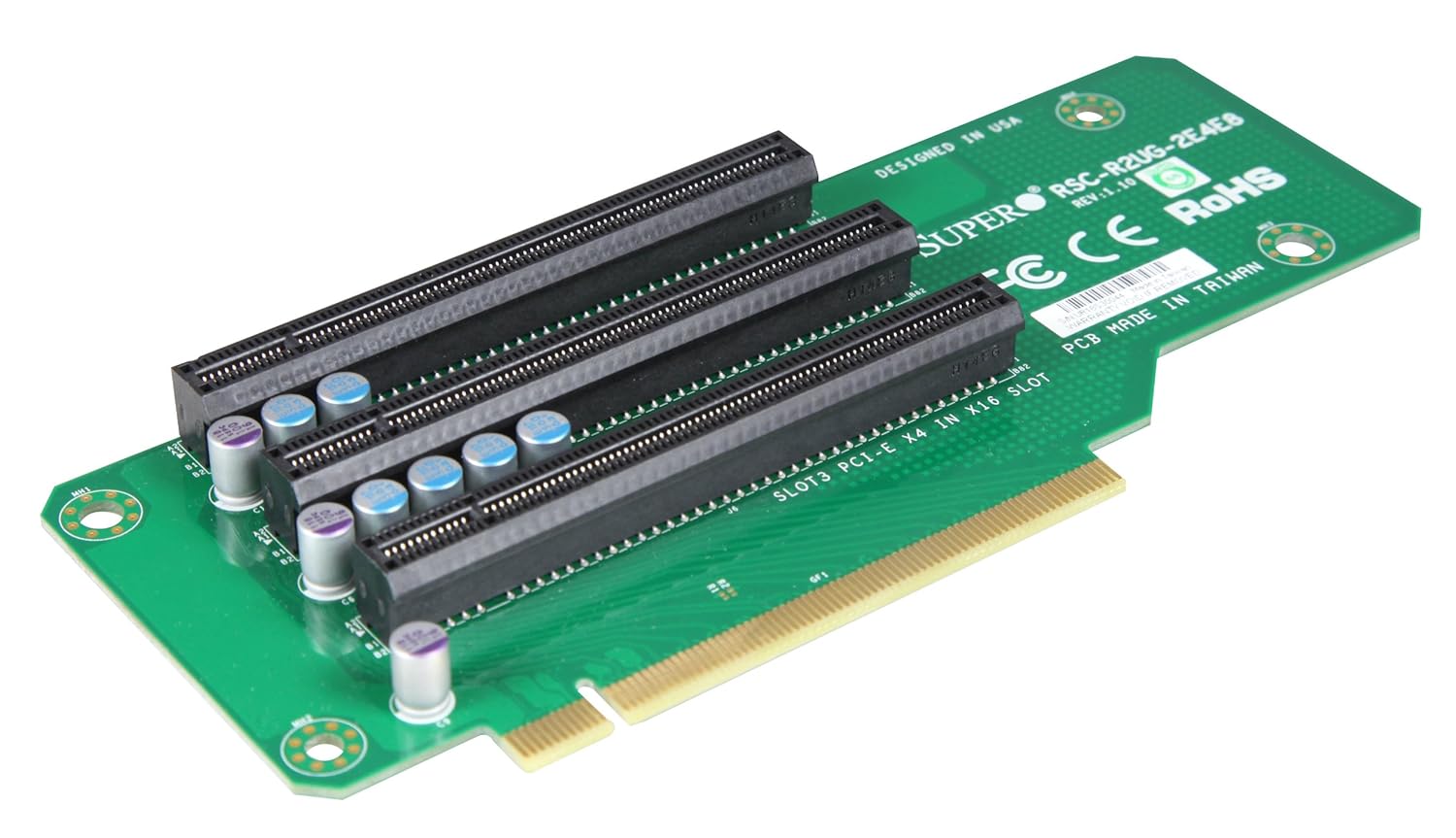
It mentions on the PCB that Slot 3 is PCIe 4x, so it actual splits the incoming 16 lanes into 8/4/4 I guess
But this one has a lot of components
http://www.acmemicro.com/Product/13546/Supermicro-RSC-R2UG-A2E16-A-LHS-Active-PCI-E-2U-Riser-Card?c_id=356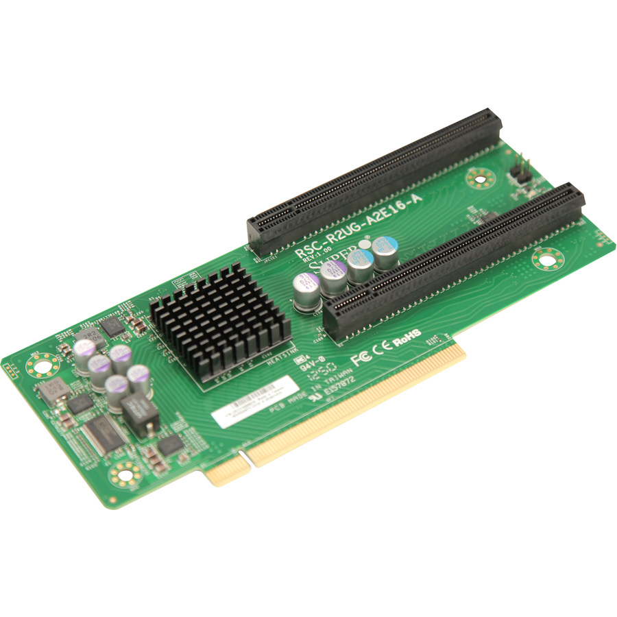
but why does it have some many components? it even has a chip that needs cooling(might be a PLX chip), PLX allow for 16X input and 2x 16X output, magic.
I hope you can assist me in figuring out what can actually be done in terms of splitting PCIe lanes.
Regards,
QinX
-
I've done some more research and there seems to be some kind of catch if you want to split an existing 16x lane to 8x/8x
It is called PCIe Bifurcation and it seems to be a feature that needs to be implemented in the BIOS.
http://www.intel.com/content/www/us/en/intelligent-systems/maho-bay/core-i7-pcie-slot-bifurcation-demo.html
However it think I should still be able to split the lanes even without it being implemented int he BIOS, but I might be need components for that.
I'm having a hard time finding exact information about it.
One of the things I came across is this Stackexchange post about the clocks is that you can't just split it.
http://electronics.stackexchange.com/questions/93264/pci-express-bifurcation-clock-fanout-buffer-needed-to-split-reference-clock -
You can only configure how the lanes are split by modding your MoBo, if that's even possible. In the video you linked to they're telling MoBo designers how they can set pins for different configurations that their board supports...
If I understand correctly they use ASMedia ASM1480 switches to switch 4 lanes per chip.
They're multiplexers, they don't let you switch the lane configuration on the fly, they let you switch between different devices on the same bus. So you can have say more than 1 PCIE 16 device hooked up even though there's only one x16 connection to the CPU. You use the multiplexers to decide which device you;'re talking to on the same serial bus. -
You have forgotten about one problem, timing. Given the speed of operation of PCIe you will need to make sure that a number of signals arrive at the connector at PRECISELY the same time, this is a significant exercise that may require a multi-layer PCB.
-
The second example card you have shown likely uses a PCIe-PCIe bridge. While the BIOS must support such a bridge in order for the connected cards to be seen at boot time, I don't think this is generally an issue. I would not be surprised if most BIOS do support them, since it is a common function. SATA3/USB3 combo cards for example usually have such a bridge. I have also seen a high performance RAID card with a PCIe bridge to enable a PCIe gen 2 chipset to have a fast interface to a PCIe gen 1 motherboard in an x4 slot.
-
You have forgotten about one problem, timing. Given the speed of operation of PCIe you will need to make sure that a number of signals arrive at the connector at PRECISELY the same time, this is a significant exercise that may require a multi-layer PCB.
Not really, PCIe does link training and has a lot of leeway, you can even switch + and - on a lane and it will adapt. You only need to match the +/- of a single pair, the pair to pair is not that critical.
I don't get paid to deskew PCIe layouts, it's never happened. DDR3, OTOH... -
You have forgotten about one problem, timing. Given the speed of operation of PCIe you will need to make sure that a number of signals arrive at the connector at PRECISELY the same time, this is a significant exercise that may require a multi-layer PCB.
PCI-E does not require pair-to-pair matching. It is routed as a group of independent differential pairs. It's actually relatively easy because of this. -
With the amount of skill, time & equipment you'd need, it would be far far cheaper just to buy a motherboard that does what you want.
PS why would you want so many PCI slots? A bitcoin miner?
-
Everyone Thank you for the replies, I'm hoping we can figure out how to make it work.
I could email a motherboard manufacturer about this, but I wouldn't know how to get my message to the right person, It'll most likely get picked up by the regular tech support.You can only configure how the lanes are split by modding your MoBo, if that's even possible. In the video you linked to they're telling MoBo designers how they can set pins for different configurations that their board supports...
If I understand correctly they use ASMedia ASM1480 switches to switch 4 lanes per chip.
They're multiplexers, they don't let you switch the lane configuration on the fly, they let you switch between different devices on the same bus. So you can have say more than 1 PCIE 16 device hooked up even though there's only one x16 connection to the CPU. You use the multiplexers to decide which device you;'re talking to on the same serial bus.
I'm not looking to switch lanes on the fly, I already figured they wouldn't work like that, however what they do seem to do is either allow the 2 slots they are connected to to be either 16x/0x ,just one card installed, or 8x/8x , two cards installed.
Note I'm talking about how these chips are implemented on motherboards, they are used in sets of 4.
What I'm interested in knowing is if I use these chips on a separate riser PCB that plugs into a 16x slot, if I could make it 8x/8x on the riser PCB.You have forgotten about one problem, timing. Given the speed of operation of PCIe you will need to make sure that a number of signals arrive at the connector at PRECISELY the same time, this is a significant exercise that may require a multi-layer PCB.
The Riser PCB that I want to make plugs into a motherboard that already has all the clocks and regulators on board. I only want to split the signals.
I already made a Riser PCB that goes from 4x on the board to 4x on the riser. The differential pairs don't need to match in length. However the 2 traces of each differental pair need to be within a certain length, I believe it was 8mil.The second example card you have shown likely uses a PCIe-PCIe bridge. While the BIOS must support such a bridge in order for the connected cards to be seen at boot time, I don't think this is generally an issue. I would not be surprised if most BIOS do support them, since it is a common function. SATA3/USB3 combo cards for example usually have such a bridge. I have also seen a high performance RAID card with a PCIe bridge to enable a PCIe gen 2 chipset to have a fast interface to a PCIe gen 1 motherboard in an x4 slot.
I've seen a so called PLX PEX8747 be used, however this chip doesn't split the lanes, it actually multiplies them, so you input 16x and get 32x out. These are power hungry, >7Watts, and are $$$. around 80 a piece, that is a no go for me.With the amount of skill, time & equipment you'd need, it would be far far cheaper just to buy a motherboard that does what you want.
PS why would you want so many PCI slots? A bitcoin miner?
I can't buy a motherboard that does what I want. I'm working on something special based on a M-ITX board.
A M-ITX only has 1 PCIe slot, often 16. However a PCIe 8x slot has plenty of bandwidth for 1 GPU. So why not have 2.
Mini DTX boards have 2 slots, but the boards out there you can count on 1 hand.
-
Note I'm talking about how these chips are implemented on motherboards, they are used in sets of 4.
They're 4 lane multiplexers, so you need 4 working in parallel to switch between 2 16 lane devices, 2 for 8 lane, 1 for 4 lane... -
Note I'm talking about how these chips are implemented on motherboards, they are used in sets of 4.
They're 4 lane multiplexers, so you need 4 working in parallel to switch between 2 16 lane devices, 2 for 8 lane, 1 for 4 lane...
I'm not so sure.
If you take a really good look at the first picture at the top, the top PCIe slot is physical 16x and signal 16x. However, the second Red PCIe slot is physical 16x and signal 8x. It only has the pins inside it to support 8 lanes. But they have 4 ASM1480 on the board between them.
So why use 4 ASM1480, capable of 16x multiplexing if you are running both slots at 8x/8x?
Hmm I've looked this one up,
MASSIVE IMAGE:
http://images.anandtech.com/doci/8449/Project_03%20.jpg
You can see how the second red and fourth red slot are wired only for 8x, but here they have 8 times the ASM1480, but I guess they have the 4 needed for the bottom slot there as well, must have been easier to route.
EDIT:
I figured it out
You have a RX and TX Pair, so there are actualy 32 pairs total. and for 8x you still have 16 pairs total. So the ASM1480 is purely used to switch 16 of the 32 pairs to the other slot.
I do think it is a hard switch. probably when a second card is detected the selection port goes high on the chips and switches 16 pairs of to the other slot.
Now would the system need to be aware of the 2 PCIe slot or will it magically work? -
So why use 4 ASM1480, capable of 16x multiplexing if you are running both slots at 8x/8x?
There are 4 red PCIE slots (guessing for the hardly ever works quad SLI) and 8 multiplexers... -
So why use 4 ASM1480, capable of 16x multiplexing if you are running both slots at 8x/8x?
There are 4 red PCIE slots (guessing for the hardly ever works quad SLI) and 8 multiplexers...
In my edit I found out that each ASM1480 switches 2 full PCIe lanes, (2 RX pairs and 2 TX pairs, or however the manufacturer implements it) so to switch 8 PCIe lanes you need 4 ASM 1480.
BUT, because these are used to allow for either 1 16x lane or 2 8x lanes they are usefull for motherboard manufacturers, but my design doesn't need that, so I shouldn't need these multiplexers. I just want to split the route the 16 lanes to 8 lanes. They question is, will motherboards/BIOS accept it.
The challenge would be the none PCIe Data lane signals
http://pinouts.ru/Slots/pci_express_pinout.shtml
I need to figure out what these signals are and what to do with them.
1) SMBus Clock
2) SMBus Data
3) TCK
4) TDI
5) TDO
6) TMS
7) +TRST#
8 ) Link Reactication
9) Power Good
10 and 11) Reference Clock pair -
You can't just split the lanes without appropriate hardware support.
The magic search term you need is PCIe switch. The 32+ lane ones are, as you've noticed, quite expensive. -
I need to figure out what these signals are and what to do with them.
1) SMBus Clock
2) SMBus Data
I2C-like configuration and monitoring bus, just put the two connectors in parallel and it will likely work if the cards use it.3) TCK
4) TDI
5) TDO
6) TMS
7) +TRST#
JTAG. Useful if you want to debug the connected hardware, but then you must know how to access the JTAG chain on your mobo. Not likely to be very useful unless you are the manufacturer of the board. The cards probably don't really need this neither for normal operation.8 ) Link Reactication
No clue, should be described in the PCIe spec.9) Power Good
Likely the system PSU power good signal. Used to tell the peripherals that it is safe to come out of reset and start powering up, because the PSU is stable already. Simply connect it to both slots.10 and 11) Reference Clock pair
System clock distribution? No idea. Should be in the spec.
-
You can't just split the lanes without appropriate hardware support.
The magic search term you need is PCIe switch. The 32+ lane ones are, as you've noticed, quite expensive.
Maybe, it might be simple in terms of hardware, hardware is just hardware and can be done by third parties. I fear it also needs software. ie the BIOS needs to do a handshake and have the code to allow for multiple cards. Seeing as a normal ATX/mATX have dual PCIe 8x slots and a mITX board with only 1 16x slot it should be doable from hardware, but if they removed the code in the BIOS to allow for this then it is going to be difficult/impossible.
I need to figure out what these signals are and what to do with them.
1) SMBus Clock
2) SMBus Data
I2C-like configuration and monitoring bus, just put the two connectors in parallel and it will likely work if the cards use it.3) TCK
4) TDI
5) TDO
6) TMS
7) +TRST#
JTAG. Useful if you want to debug the connected hardware, but then you must know how to access the JTAG chain on your mobo. Not likely to be very useful unless you are the manufacturer of the board. The cards probably don't really need this neither for normal operation.8 ) Link Reactication
No clue, should be described in the PCIe spec.9) Power Good
Likely the system PSU power good signal. Used to tell the peripherals that it is safe to come out of reset and start powering up, because the PSU is stable already. Simply connect it to both slots.10 and 11) Reference Clock pair
System clock distribution? No idea. Should be in the spec.
Thank you for identifying 1 through 7.
9 should have been obvious the first time I read it
8 is a WAKE signal, it communicates the power state of the card to the host. It might not be needed but power consumption might become worse because it. Will have to look into it some ore.
https://www.pcisig.com/developers/main/training_materials/get_document?doc_id=3ba5129826fa0214e5cd85fb70ff38e1df32a11c
10 and 11)
this is the 100MHz reference clock. This might be a tricky one.
http://electronics.stackexchange.com/questions/93264/pci-express-bifurcation-clock-fanout-buffer-needed-to-split-reference-clock
But again if it is generated from 1 source and is supplied to multiple PCIe slots on some boards, there may be a simple answer. -
You can't just split the lanes without appropriate hardware support.
The magic search term you need is PCIe switch. The 32+ lane ones are, as you've noticed, quite expensive.
Maybe, it might be simple in terms of hardware, hardware is just hardware and can be done by third parties. I fear it also needs software. ie the BIOS needs to do a handshake and have the code to allow for multiple cards. Seeing as a normal ATX/mATX have dual PCIe 8x slots and a mITX board with only 1 16x slot it should be doable from hardware, but if they removed the code in the BIOS to allow for this then it is going to be difficult/impossible.
Just because the chipset can be used that way doesn't mean you can just split the lanes on any old board and expect it to work. Both the board and the BIOS need to be built to allow it.
If you want to use an existing board you will need to use a packet switch. They are expensive if you want 32+ lanes.
If you can get away with 12 lanes (x4 host > two x4 cards) they're more affordable. -
You can't just split the lanes without appropriate hardware support.
The magic search term you need is PCIe switch. The 32+ lane ones are, as you've noticed, quite expensive.
Maybe, it might be simple in terms of hardware, hardware is just hardware and can be done by third parties. I fear it also needs software. ie the BIOS needs to do a handshake and have the code to allow for multiple cards. Seeing as a normal ATX/mATX have dual PCIe 8x slots and a mITX board with only 1 16x slot it should be doable from hardware, but if they removed the code in the BIOS to allow for this then it is going to be difficult/impossible.
Just because the chipset can be used that way doesn't mean you can just split the lanes on any old board and expect it to work. Both the board and the BIOS need to be built to allow it.
If you want to use an existing board you will need to use a packet switch. They are expensive if you want 32+ lanes.
If you can get away with 12 lanes (x4 host > two x4 cards) they're more affordable.
It shouldn't need a 80 dollar chip to do it.
Why? because of the following.
Scenario:
Chipset is not important for me, because Intel CPUs of the Ivy-bridge generation and later have >16 PCIe 3.0 lanes available directly from the CPU, no chipset is between the GPU and the CPU.
The ASUS Maximus VII Hero has 2 PCIe 16x slots, but when 2 cards are installed these operate at 8x they only use the ASM1480 chips to change lane allocation from 16x/0x to 8x/8x no fancy chip needed.
the ASUS Rampage VII Impact is based on the exact same platform as the Hero, but it is in mITX format so it only has 1 physical PCIe slot.
What is stopping me from just adding the same components ASUS added to the motherboard to allow for the lanes to split?
The only thing I can't do is change the code for the BIOS. IF it is needed, I suspect it will need it.
If I want to be able to do it with every board, then I would need the PLX PEX8747. But seeing as that is no possible for me I want to figure out if I can do it the cheap way. If it turns out that you have to have a BIOS that supports it than I will know it can't be done without manufacturer cooperation. -
Scenario:
Chipset is not important for me, because Intel CPUs of the Ivy-bridge generation and later have >16 PCIe 3.0 lanes available directly from the CPU, no chipset is between the GPU and the CPU.
Chipset, CPU integrated host.. same difference. It is the upstream, I don't care where it comes from.QuoteThe ASUS Maximus VII Hero has 2 PCIe 16x slots, but when 2 cards are installed these operate at 8x they only use the ASM1480 chips to change lane allocation from 16x/0x to 8x/8x no fancy chip needed.
And it has presence pins, clock buffers, and logic to detect cards inserted in the extra slot and have the BIOS configure the PCI-E controller to operate the bus as two x8 ports.Quotethe ASUS Rampage VII Impact is based on the exact same platform as the Hero, but it is in mITX format so it only has 1 physical PCIe slot.
What is stopping me from just adding the same components ASUS added to the motherboard to allow for the lanes to split?
The lack of all the above. -
Okay, I'm starting to understand, still not totaly sure though.
How would this card work then?
RSC-R2UG-2e4e8
http://www.acmemicro.com/Product/13545/Supermicro-RSC-R2UG-2E4E8-LHS-Passive-2U-PCI-E-Riser-Card?c_id=356
It has the following specs
Output Type: Output: (3) PCI-E x16 , Signal: (1) PCI-E x8, (2) PCI-E x4
GenN: gen2: Yes , gen3: No
GPU / PHI Support:
Auto Detect: Yes
Compatible System: 2026GT-TRF, 2026GT-TRF-FM407, 2026GT-TRF-FM409, 2026GT-TF
There are 5 undefined pins on a 16x PCIe slot, they might have used those, but would that be enough to add 2 more PCIe slots? -
How would this card work then?
RSC-R2UG-2e4e8
http://www.acmemicro.com/Product/13545/Supermicro-RSC-R2UG-2E4E8-LHS-Passive-2U-PCI-E-Riser-Card?c_id=356
It has the following specs
Output Type: Output: (3) PCI-E x16 , Signal: (1) PCI-E x8, (2) PCI-E x4
GenN: gen2: Yes , gen3: No
GPU / PHI Support:
Auto Detect: Yes
Compatible System: 2026GT-TRF, 2026GT-TRF-FM407, 2026GT-TRF-FM409, 2026GT-TF
There are 5 undefined pins on a 16x PCIe slot, they might have used those, but would that be enough to add 2 more PCIe slots?
My guess this riserboard only works on certain server boards that supermicro makes (first guess, didn't actually do any research). Will prolly be cheaper to just supply some support for this on their mobos in case the user wants to use it. So the chips it lacks compared to that other splitter card will simply be present on the motherboard. -
How would this card work then?
RSC-R2UG-2e4e8
http://www.acmemicro.com/Product/13545/Supermicro-RSC-R2UG-2E4E8-LHS-Passive-2U-PCI-E-Riser-Card?c_id=356
It has the following specs
Output Type: Output: (3) PCI-E x16 , Signal: (1) PCI-E x8, (2) PCI-E x4
GenN: gen2: Yes , gen3: No
GPU / PHI Support:
Auto Detect: Yes
Compatible System: 2026GT-TRF, 2026GT-TRF-FM407, 2026GT-TRF-FM409, 2026GT-TF
There are 5 undefined pins on a 16x PCIe slot, they might have used those, but would that be enough to add 2 more PCIe slots?
My guess this riserboard only works on certain server boards that supermicro makes (first guess, didn't actually do any research). Will prolly be cheaper to just supply some support for this on their mobos in case the user wants to use it. So the chips it lacks compared to that other splitter card will simply be present on the motherboard.
It does only work on certain supermicro boards, but lets try and figure out why. If they adhere to the PCIe specification than they can't send any extra clocks or signals over the lanes.
If they deviated from the spec the question becomes how much?
There are 6 Reserved pins on a PCIe 16x slot. The could use those without changing the function of the allocated pins. Would that allow them to go from 1 to 3 PCIe devices?
the first device receives the extra signals from the PCIe slots regular pins, the other 2 would have 3 pins each.
I suppose they would only need the WAKE signal and perhaps the reference clock. which would be 3 pins total for each device,
There are also a lot of GND connections, if they use those from some extra signaling then they are no longer adhering to the PCIe spec. Which should be fine for them if they only support certain boards of their own.
I've shot SuperMicro an email to see if they would send me some technical information. -
I've been in contact with SuperMicro, they tried to help but also didn't.
In the end I order a Riser Card and worked out the traces.
So only the Reference Clock seems to be needed as an extra, besides some BIOS changes I'd imagine.
Hardware wise it doesn't seem as hard as it could have been, I just need to figure out a way to turn 1 Reference clock pair into 2 on the PCB.
I found this, but I'm not sure it is what I need.
IDT 9DB23 (Two Output Differntial Buffer for PCIe Gen3)
If somebody can provide some insight?
Edit:
So I read the IDT 9DB233 datasheet, I think this is what I need.
it's a 20-pin TSSOP, it has an SMBus for controlling the PLL, but I don't think it is needed. If you just keep all of it low then it should just perform as a fanout for turning 1 diff pair into 2.
-
Bump!
I had email ASUS about the possibility of doing this.
They also mentioned that although PCIe Bifurcation is support on current generation Intel Core processor it needs to have some code written in the BIOS for detection and setting it up.
The PCIe Bifurcation is used on a lot of highend motherboard, but I want to use a M-ITX board, and guess what, only 1 PCIe slot means they don't need the code. So I'm going to have to persuade someone to add this code
I do believe that I am on the right track. -
If you actually succeed at making ASUS to write you a BIOS patch for a one off board, hats off ...
Unless you are golf mates with the CEO or something at a similar level, it is about as likely to happen as hell freezing over - it is a fairly significant engineering work you are most likely not ready to pay for and not economical for them unless you are willing to buy at least few hundreds/thousands of those boards.