-
Piezoelectric hydrophone low noise amplifier design questions
Posted by Sparker on 21 Apr, 2018 13:24 -
Hello guys!
I always feel a beginner when it comes to analog things, so I need help with this sensitive topic.
So, I need to design an LNA for a piezoelectric hydrophone to later digitize the signal with a single-ended ADC (the ADC of my STM32 for now). Hydrophone works both in TX and RX modes (it's for a sonar).
Antenna properties: operating at ~240 kHz, nothing else is known about it now.
Specs for the amplifier are: input voltage is expected to be in the order of 10's of uVolts, so I need ~10^5 voltage gain. Double-pole bandpass frequency response centered at 240 kHz with Q~10 is probably OK as it will be later processed with DSP. Also I want to digitally(from an MCU) control its gain in, at least, 20 dB range or so.
Also this thing is going to be installed not far from noisy things like a lot of DC-DC converters for powerful LEDs.
I intend to make it with high frequency opamps. For the gain-control part I will probably use some digital potentiometer between gain stages(or is there a better choise?). Also i can design the active filter part myself.
When it comes to the first stage of the amplifier, I am not sure what to do. I am considering two options:
1. I am not experienced with noise-sensitive things, but I guess that the common mode rejection ratio mentioned everywhere is an important part in this device to suppress common noise at inputs. I could make the first stage with a transformer(to serve as unbalanced->balanced converter) followed by a low noise high speed opamp, like one of these: AD8646, AD8651, AD8655 or OP37. But I am not sure about CMRR of a transformer, especially if it will be hand-wound on some ferrite ring. How high can it be?
2. Another option is to eliminate the transformer and take a nice instrumentation amplifier like INA128 or INA2128. One more cool instr. amp. I found is AD8231, more noisy but hey, it has digitally-programmable gain.
One more piece of advice I have seen in the Internet is to go fully differential from input to ADC (Once I had a look at a professional Imagenex sonar board, and they did exactly that with fully-differential opamps). But I am not sure how much sense it makes in my case if I am using a single-ended ADC.
Also one more general thing I would like to clarify about opamp circuit design is this: if I only care about high frequency part of spectrum, should I care much about opamp specs like offset voltage and input current? As I understand it makes huge difference only if I were to amplify DC signals.
Thanks to anyone who has made it through this wall of text!
-
I am just going to ramble.
input voltage is expected to be in the order of 10's of uVolts, so I need ~10^5 voltage gain.
With that much gain over the same frequency range, you will have to be careful about coupling between stages causing oscillation. Superheterodyne radio receivers avoid this problem by mixing so they can distribute the gain over different frequency ranges limiting the game at any intermediate frequency.QuoteI intend to make it with high frequency opamps. For the gain-control part I will probably use some digital potentiometer between gain stages(or is there a better choise?).
Operational amplifiers are probably the easiest as far as design. For the stages after the input stage, I would probably use current feedback operational amplifiers but operational transconductance amplifiers can combine gain control and bandpass filtering in one stage so might be worth considering.
Someone might still make an integrated intermediate frequency amplifier intended for AM receivers which could be used in an application like this. 240kHz isn't that far from 455kHz.Quote1. I am not experienced with noise-sensitive things, but I guess that the common mode rejection ratio mentioned everywhere is an important part in this device to suppress common noise at inputs.
See below about input stage differential inputs.
Power supply rejection ratio matters for limiting input noise as well. Consider using a separate low noise voltage regulator for the input stage.QuoteI could make the first stage with a transformer(to serve as unbalanced->balanced converter) followed by a low noise high speed opamp, like one of these:
Another option is to eliminate the transformer and take a nice instrumentation amplifier
If you have a differential input, then noise is doubled but this does not matter for later stages. A transformer can be used for impedance matching to minimize input noise and drive a single ended input from a differential source avoiding the increased noise of a differential input. The impedance matching from the transformer gives a lot more leeway in selecting an input amplifier.
I think you can get lower input noise with a discrete input stage but the improvement may not be significant.QuoteOne more piece of advice I have seen in the Internet is to go fully differential from input to ADC (Once I had a look at a professional Imagenex sonar board, and they did exactly that with fully-differential opamps
). But I am not sure how much sense it makes in my case if I am using a single-ended ADC.
There is a lot to recommend using a differential signal path except for the transducer signal input as mentioned above. Power supply noise including interference from other stages of the amplifier gets rejected as common mode noise so this can help prevent oscillation.QuoteAlso one more general thing I would like to clarify about opamp circuit design is this: if I only care about high frequency part of spectrum, should I care much about opamp specs like offset voltage and input current? As I understand it makes huge difference only if I were to amplify DC signals.
Since you can use AC coupling, input offset voltage does not matter. Input bias current can still be an issue because it comes with input current noise which combined with input impedance adds to the input voltage noise but this is unimportant after the low noise input stages.
-
Hello, David! Thanks for your advice on the design of this circuit!
I don't have any experience with current feedback or transconductance amps yet, but I will see what I can do with them in a simulator.
As for the transformer, as I understand I must use it to match source resistance to input resistance for optimal noise. But I'm not sure if I will ever know it, unfortunately.
It is only not clear for me why there is noise increase in case of differential inputs. I thought that differential inputs are meant for decrease of noise. -
What's the bandwidth? I presume it's not necessary to go from DC to 240kHz? I imagine the bandwidth is very narrow.
An AM radio-style receiver sounds like a good idea. The signal could be heterodyned down to much lower frequency, thus lowering the noise, the sample rate and processing requirements. -
Quote
What's the bandwidth? I presume it's not necessary to go from DC to 240kHz? I imagine the bandwidth is very narrow.
You are right, BW is narrow, that's what I meant by "Double-pole bandpass frequency response centered at 240 kHz with Q~10" in my initial message.
I am using undersampling to digitize it, the 240kHz carrier aliases to fs/4, then I use DSP techniques to demodulate it.
I agree that an AM receiver IC might suitable for the task, in fact I've seen some old soviet IC like this used in one of our other sonars. -
I don't have any experience with current feedback or transconductance amps yet, but I will see what I can do with them in a simulator.
Current feedback operational amplifiers are used like voltage feedback operational amplifiers but their gain-bandwidth product is controlled by their feedback resistance. So as their voltage gain goes up, so does their gain-bandwidth product. Voltage feedback amplifiers have a fixed gain-bandwidth product so they have lower bandwidth as their gain increases unless they support external compensation which is very rare in modern parts; offhand, I do not know of any.
Operational transconductance amplifiers are designed to operate without feedback and have a separate current input which controls their transconductance making them useful as a variable gain amplifier. The Linear Technology (now Analog Devices) LT1228, Burr-Brown (now Texas Instruments) OPA860/OPA861, and old slow National LM13700 are examples of these. They usually convert their current output into a voltage using a resistive load for flat bandwidth response but they can also drive a tuned load directly for a bandpass response.QuoteAs for the transformer, as I understand I must use it to match source resistance to input resistance for optimal noise. But I'm not sure if I will ever know it, unfortunately.
It is not exact about matching source and load resistance for maximum power transfer. The input amplifier has a ratio of voltage to current noise which can be matched to the source impedance. So the transformer effectively gives free noiseless voltage (or current) gain if the amplifier's input noise resistance does not match the source.QuoteIt is only not clear for me why there is noise increase in case of differential inputs. I thought that differential inputs are meant for decrease of noise.
Differential inputs remove common mode noise but because there are two active circuit paths, the differential noise from each one adds to increase the differential noise.
-
Not all ADCs have high bandwidth sample and hold. Whether you go fully differential will depend on the ADC you pick, if it's single ended go single ended after the first stage.
-
Be sure to include over-voltage protection for the input amplifier. Piezoelectric hydrophones can generate large voltages when excited by vibrations or other mechanical disturbances. Static charge can also build up due to temperature changes. In sonar systems, it is good practice to place back to back diodes across the input for this purpose. Note that amplifiers used in Naval sonar systems also have to be protected against the voltages generated by explosives such as depth charges.
-
Quote
Not all ADCs have high bandwidth sample and hold. Whether you go fully differential will depend on the ADC you pick, if it's single ended go single ended after the first stage.
The STM32 ADC can work up to 2.4 MSPS, while I'm going to use it at 192 kHz. Also it has configurable sample time, so i think it's going to be fine. Ar am I missing something which will prevent the ADC from working well in undersampling mode?QuoteBe sure to include over-voltage protection for the input amplifier. Piezoelectric hydrophones can generate large voltages when excited by vibrations or other mechanical disturbances. Static charge can also build up due to temperature changes. In sonar systems, it is good practice to place back to back diodes across the input for this purpose.
Thanks, I'm aware of these diodes, just didn't mention them.QuoteNote that amplifiers used in Naval sonar systems also have to be protected against the voltages generated by explosives such as depth charges.
That's an interesting fact, but we are building a peaceful sonar.QuoteOperational transconductance amplifiers are designed to operate without feedback and have a separate current input which controls their transconductance making them useful as a variable gain amplifier. The Linear Technology (now Analog Devices) LT1228, Burr-Brown (now Texas Instruments) OPA860/OPA861, and old slow National LM13700 are examples of these. They usually convert their current output into a voltage using a resistive load for flat bandwidth response but they can also drive a tuned load directly for a bandpass response.
Thanks again, David, I've looked through the applications of these devices and they are impressive. The LT1228 device you've mentioned seems to be perfect for my case, but unfortunately anything except the old & slow LM13700 is extremely hard to get here. I guess that the 2MHz of BW of LM13700 is too impractical for my case.
Now I think I will stick with transformer input design, to adjust its winding for noise if needed, as you suggested. Also, if I connect the input transformer between the + input of the CFB Opamp and the ground, does anything prevent me from also using the CFB opamp for the first stage? -
The STM32 ADC can work up to 2.4 MSPS, while I'm going to use it at 192 kHz. Also it has configurable sample time, so i think it's going to be fine. Ar am I missing something which will prevent the ADC from working well in undersampling mode?
No, you just don't need a differential chain then. Use a transformer for "free" voltage gain and common mode rejection as a first stage and some precision JFET opamp (OPA140?) as a single ended amplifier after it (JFET for the low current noise, the transformer amplifies current noise, it's the trade off for the voltage gain ... not free after all). -
Now I think I will stick with transformer input design, to adjust its winding for noise if needed, as you suggested. Also, if I connect the input transformer between the + input of the CFB Opamp and the ground, does anything prevent me from also using the CFB opamp for the first stage?
Input noise still counts and I think voltage feedback operational amplifiers have an advantage here but I have not studied the current feedback operational amplifier option in detail. To put it another way, nobody that I know of is using current feedback operational amplifiers (or transconductance amplifiers, see below) for low noise input stages.
Giving it a little bit of thought, this makes perfect sense. Current feedback amplifiers are closely related to transconductance amplifiers (1) where the resistance in series with the emitter sets the transconductance which is effectively the gain. That same resistance however in series with the emitter also adds directly to the input noise; as far as the transistor is concerned, noise in series with the emitter is the same as noise in series with the base and since the emitter operates at much higher current, a small amount of resistance there has a large effect on noise.
Fast voltage feedback operational amplifiers, often called video amplifiers, also usually include a resistor in series with the emitters of the input stage to lower transconductance which counter intuitively, allows for higher speed. (2) But this *also* makes them noisy. The very old example of this is the LM318 but modern video amplifiers do the same thing and you can often find this used in audio amplifiers where the increased gain-bandwidth product yields lower distortion, but again at the expense of higher input noise.
So no, I do not recommend using a current feedback operational amplifier or operational transconductance amplifier for the low noise input stage.
Low noise hydrophone amplifiers usually use low noise FET input voltage feedback amplifiers (and no input transformer) however this is because the low input bias current of an FET extends low frequency operation which you do not need. But a low noise FET input voltage feedback operational amplifier would still be a good choice at least to start off with.
(1) Not necessarily operational transconductance amplifiers which have an input stage identical to a voltage feedback operational amplifier but a quick inspection shows they are pretty noisy also although I do not understand why. Some old voltage feedback operational amplifier provide access to their transconductance output through their external compensation pin so they obviously have the same noise specifications when used either way.
(2) This is called transconductance reduction or Gm reduction. Low noise amplifiers which need transconductance reduction do it in a different way which does not require adding resistance in series with the emitters.
-
Why not use a transformer? It's probably be going to be an expensive one, since you want really high permeability to keep the number of windings on the secondary low ... but it does allow you to drop noise a bit and do common mode rejection without needing a differential amplifier.
-
Sorry for not answering for a few days!
You guys are right about the noise, I obviously forgot about the input current noise influence when I made my assumption of using the CFB op-amp as input stage
Inspecting this spec for a voltage feedback CMOS device and current feedback BJT device made it clear for me:
CMOS device: AD8651, Current noise density: 4 fA/sqrt(Hz)
BJT device: AD812, Input current noise, + input: 1.5 pA/sqrt(Hz), or bigger by about 3 orders!
Now, by using the AD8651 CMOS input opamp at input and two more stages of AD812 CFB opamps, with a Sallen-Key filter around the second stage, I was able to assemble this circuit in LTSpice(please see attachment). Input transformer is omitted in the model but I will install it in the real circuit.
I was going to add digitally controllable gain, and for that I chose MCP41010 10kOhm digital potentiometer, which is emulated in the circuit by R11. It is the only one I could find with low parasitic capacities (C_A, C_B and C_wiper in the circuit). This digital potentiometer can only tolerate voltages between its GND and Vcc, so I decided I will power it with the analog rails, since they have 5 Volts between them, and shift the logic levels down from the MCU levels (0...3.3V) to (-2.5V...2.5V) with a little BJT circuit(omitted in this model).
I'd be grateful if you have a glance at the schematic, maybe you can see some obvious faults which I don't see.
-
Do not forget that without an input transformer, the input amplifier requires a ground return for its input bias current because the transducer is open at DC.
-
OPA140 has 5x lower current noise than the AD8651, but that doesn't really matter at the 10-100 Ohm impedance range the transducer probably falls in near resonance ... at least not without a transformer with gain (with 10+ voltage gain with a transformer it might start mattering). AD812 looks a bit expensive, unless you need the output current capability. Why use a digital potentiometer instead of a PGA (PGA112 for instance). That way you don't need that 400x amplification on that last stage either, that's pushing it a bit.
-
Exactly how large is the piezoelectric microphone? Specifically, how much capacitance does it have and what will be the length of cable between the microphone and input amplifier?
It matters because if operation down to low frequencies is not a requirement, then the capacitance at high frequencies determines the input impedance and the optimum ratio between voltage and current noise. Conceivably a bipolar input operational amplifier with much lower voltage noise is a better choice if the frequency is high and the capacitance is large. The required bias current resistor, which is needed anyway unless a transformer is not used, can be chosen based on the low frequency cutoff and capacitance.
Some hydrophone amplifier designs include a second DC servo loop to cancel the input bias current while providing a higher input resistance for extended the low frequency response but that does not apply here.
-
Exact data on the piezoelectric antenna is unknown yet. I'd love to know and give more data, but I can't. I can only say that it will be a one-dimensional array or piezoelectric elements(to have high directivity in orthogonal direction). Something like this one:
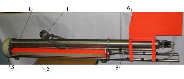
The part marked as "2" is the antenna, it has a row of elements connected in parallel and it's filled with epoxy.
The cable length will be about a meter.QuoteWhy use a digital potentiometer instead of a PGA (PGA112 for instance).
Thanks, but I think i will stay with the digital pot. variant since it gives more gain values. And I can lower the final stage gain later if I encounter problems.
AD812 might be expensive but it has two opamps in one case. There aren't a lot of opamps like these I can choose from without waiting for them for two weeks to be delivered. -
I found some datasheets and the capacitance is 1000s to 10,000s of picofarads like I expected. So at 240kHz, that is 664 ohms and 66.4 ohms of reactance so a low noise bipolar input operational amplifier *is* suitable because the current noise of such a part into such a low reactance will produce an equal or lower voltage noise than the input voltage noise of the amplifier itself. (1) Of course the details will depend on exactly the capacitance of the piezoelectric hydrophone. At lower frequencies and with smaller transducers which have lower capacitance, the current noise needs to be lower because the transducer's reactance is higher giving JFET or MOSFET input amplifiers the advantage and the same thing happens if an input transformer is used to raise the transducer's impedance.
So with the current situation assuming a 1000pF transducer, I think you would have about a 6 to 12 dB noise advantage with suitable bipolar input operational amplifier at 240kHz because the input capacitance is so high but with a 4:1 or higher ratio transformer, a JFET or MOSFET input amplifier will be necessary because bipolar parts with a suitably low current noise will not be fast enough. With a 10,000pF transducer, a transformer could even be used with a bipolar input part.
(1) You still have to deal with returning the input bias current to ground, whether a bipolar, JFET, or MOSFET input is used, but that just means shunting it with an inductance or resistance. A shunt resistor forms the first pole of your high pass response attenuating low frequencies.
-
Could you share the datasheets, please? I'd like to see the real-imaginary impedance plots of real assemblies.
Thanks a lot for such in-depth analysis of my problem. I have learned a lot from your messages!
I might be wrong again, but I expected that the antenna will work at its resonant frequency, and its impedance should be active at this frequency. -
This is the datasheet I found:
http://www.lthe.fr/LTHE/IMG/pdf/DocBruelKjaerHydro.pdf
I only used it to make a rough estimate and I suspect your device being an array will have a capacitance at the higher end of what I estimated.
The short summary of what I posted is that you cannot go wrong with a low noise JFET or MOSFET operational amplifier but I think under ideal conditions at least another 6 to 12 dB is possible with a bipolar part and even more if a transformer is used because the source impedance is so low.
-
Feeling extremely unprofessional now
I intended to use the protection circuit below(1st attachment) at the amplifier input. It's an inherited variant used with other sonars here. I didn't add the 1k resistors to the simulation, but it turns out that a 1k resistor generates 4 nV/sqrt(Hz) of noise(and two of them give sqrt(2) times more), about the same amount as the op amp itself, assuming a 1:1 transformer. It kind of nullifies our efforts to make a low noise input stage.
Thinking of it, I decided to take a better look at the photos of the commercial Starfish sonar board(link) I made some time ago in hope to get insight of how this is properly done.
It's quite an interesting device. They emit 430kHz-470kHz CHIRP pulses and do DSP with an FPGA. The receive path is made of two THS4130 fully-differential op-amp stages, followed by a LTC1403 14-Bit 2.8 MSPS ADC. Probably they don't do analog bandpass filtering, but I didn't analyse the circuit enough to be sure.
The first stage opamp configuration appears to be an inverting amplifier with 220 Ohm input resistor and 47 kOhm feedback resistor, giving 46 dB gain. See the picture below(last attachment) for the recovered schematic of the input.
What I don't quite understand is why is their amplifier's input impedance so low(220 Ohm) while we typically want higher input impedanse for such a sensitive device.
-
AFAICS these small thickness mode resonant fish finder piezo discs have an impedance of ~10 Ohm at resonance, so even 220 Ohm is probably high enough.
With a FDA input stage you're limited in options for low noise. Can't increase input impedance without increasing noise, so it's always a bit of a compromise. There are other architectures for low noise differential amplifiers which avoid this, but not in IC form (closest would be AD8129 but that's not exactly low noise).
Personally I'd wind a transformer for ~10x voltage gain using a nice expensive toroid and use a discrete input stage like pic (for high amplification it would need to be modified a bit, more like the one from Vojtěch Janásek which I mocked up in the second pic, or if you want you can parallel BF862s like GK described here on the forum, but I doubt you'd get away with 100x amplification in that case). Connect it to the fishfinder piezo and hit it with a hammer to see if the input protection is good enough.
PS. the input impedance of the starfish inputs is 1220 Ohm, not 220 Ohm. The 1K is simply in series with the 220 Ohm resistor as far as the signal is concerned. Don't let the coupling capacitors and diodes fool you.
-
I intended to use the protection circuit below(1st attachment) at the amplifier input. It's an inherited variant used with other sonars here. I didn't add the 1k resistors to the simulation, but it turns out that a 1k resistor generates 4 nV/sqrt(Hz) of noise(and two of them give sqrt(2) times more), about the same amount as the op amp itself, assuming a 1:1 transformer. It kind of nullifies our efforts to make a low noise input stage.
That is one of the reasons I said earlier that you cannot go wrong with a FET input operational amplifier; the series resistance added by simple input protection circuits raises the noise level. Using a lower noise bipolar operational amplifier requires something more complex than a series resistor and shunt, some type of transmit/receive switch perhaps.
It is possible to make low impedance switches and overdrive protection circuits using diodes. Perhaps easier in this case is to put a pair of depletion mode power MOSFETs back to back with a source resistor to set a current limit in place of those 1k resistors. Below the current limit, the resistance is just the source resistor and MOSFET channel resistances. Above the current limit, the channel resistances increases with voltage to product a constant current.
The diode method uses no resistors at all but is pretty esoteric and may produce too much noise. I have only seen it used in 50 ohm RF systems where this was not a problem. Check out the Tektronix 7A29 vertical amplifier and 485 oscilloscope for examples where this was used.QuoteWhat I don't quite understand is why is their amplifier's input impedance so low(220 Ohm) while we typically want higher input impedanse for such a sensitive device.
The piezoelectric hydrophones have a low impedance to start with because they are so large. The impedance translates into an optimum ratio of voltage noise to current noise at the input to the amplifier. That is why a bipolar input amplifier with lower voltage noise but higher current noise is more optimal for the examples I gave but this can be offset by raising the impedance with a transformer to take better advantage of the higher voltage noise but almost zero current noise of a FET input operational amplifier. It is also easier to implement protection circuits for FET input amplifiers which is an overriding concern if the design is to be kept simple.
In the example schematic there is another reason; the amplifier will be very unhappy with a capacitive source on its inverting inputs (two of them for the shunt feedback differential amplifier shown) without series resistance. I really think that is the wrong way to go about this; at the very least, a non-inverting differential amplifier should be used which is the first half of the 3 operational amplifier instrumentation amplifier. That avoids the whole problem. The same circuit can be built with a pair of low noise JFETs or even better, a transformer and singled ended amplifier as we discussed earlier.
Does the piezoelectric hydrophone's connection really need to be differential or could one side be grounded? I have never messed with one.
-
The diode method uses no resistors at all but is pretty esoteric and may produce too much noise.
The diodes in the second schematic I posted and in a simple non inverting amplifier between the +/- inputs of the opamp are bootstrapped to nearly the same voltage, they can be much chunkier than the diodes to the rails the FDA has because their effective capacitance is reduced. The TVS/MOV to ground is in parallel with a very low impedance (1 Ohm in this case) so at 200 kHz that's pretty much irrelevant. A MOV is probably fast enough for any spikes coming from the piezo, so that would be the preferred option.
You could put chunky diodes between the +/- inputs of a discrete instrumentation opamp configuration as well of course. You can't realistically get close to the noise performance of a transformer based design though and if you use a transformer you can use a simple single ended amplifier, because the transformer takes care of common mode noise. In simulation the second schematic has a noise level of 0.86 nV/rtHz with a series resistance on the input of 100 Ohm (set to be noiseless, only amplifying current noise). This would suggest 0.086 nV/rtHz with a 10x transformer, assuming the transducer has about 10 Ohm impedance at resonance ... getting there without a transformer seems almost impossible. -
Thanks for the help again, Marco and David!
Marco, it's quite a mystery to me how the JFET circuit you've mentioned works. I understand that the op-amp helps the JFET's biasing, but I don't understand the AC behaviour of the circuit.
The problem with your diode based protection is that, maybe I didn't mention it good enough, the antena works both in TX and RX modes, so when we are transmitting the impulse, about 50...100 volts will be applied to the protection circuit, thus it should have some kind of series protection.QuotePS. the input impedance of the starfish inputs is 1220 Ohm, not 220 Ohm. The 1K is simply in series with the 220 Ohm resistor as far as the signal is concerned. Don't let the coupling capacitors and diodes fool you.
Agree. I virtualy moved the 1k resistors to the generator side in my mind when I was typing this.QuoteIt is possible to make low impedance switches and overdrive protection circuits using diodes. Perhaps easier in this case is to put a pair of depletion mode power MOSFETs back to back with a source resistor to set a current limit in place of those 1k resistors. Below the current limit, the resistance is just the source resistor and MOSFET channel resistances. Above the current limit, the channel resistances increases with voltage to product a constant current.
Thanks, I think it's a brilliant idea! I will try to investigate this possibility with the depletion MOSETS I can buy here.QuoteDoes the piezoelectric hydrophone's connection really need to be differential or could one side be grounded? I have never messed with one.
It can be grounded, but concluding from what I've read about differential signaling, it offers better noise reduction. Even the designers of the starfish device use differential signals: for each channel there are two wires and a grounded shield.QuoteIn the example schematic there is another reason; the amplifier will be very unhappy with a capacitive source on its inverting inputs (two of them for the shunt feedback differential amplifier shown) without series resistance.
Indeed, as the amplifier's gain is -Z2/Z1, having a capacitor as Z1 in the denominator just asks for a trouble.