-
Square Wave From Signal Generator on Rigol MSO1104 Not Square
Posted by SewingYard on 19 Apr, 2016 20:48 -
Hi,
Another newbie question that I'd love to know where I'm going wrong.
I have my scope setup with a BNC from the signal generator, the sig gen is set to a Square Wave at 15MHz at 5v
It goes straight to the scope probe that's connected to CH1 set to x10 with DC coupling at 2v and 10ns
The problem is the wave looks more like a dodgy sine wave than a square wave, the lower the frequency I go for the more it looks like a true square wave.
I always thought a signal gen connected straight to the scope would create a perfect wave, is this still true even at higher frequencies or does the resistance / capacitance of the probe get in the way?
Thanks. -
As a follow-up question. Is there really such a thing as a square wave?
to OP - I think you will get better answers if you post a picture. I know there is no perfect square wave. -
I have similar results as the OP with my 15Mhz Agilent 33120A.
The reason for that is the minimum signal rise time.
Meaning that the signal can simply not rise fast enough for you to see a square wave at 15Mhz.
If you for example set the frequency from 15Mhz to 100kHz but don't change the time scale on the scope, you'll see that the rising edge should look the same, the thing is that at 15Mhz you're zooming enough to notice it.
Check the specs on your signal generator, what's the rise time ?
Also what scope are you using ? -
Check for proper termination. Sig gen outputs are usually 50ohm and the coax should be terminated at the scope end. If the scope had 50 ohm input mode use that, or use 50 ohm feedthrough terminator.
This will do magic with fast rise signals. -
Michaelv is right, rise time on the signal generator is 15ns. This is what I see on an MSO1074Z-S (liberated).
Edit: I did try it with an inline terminator at the time of the test too, the signal actually looked slightly worse!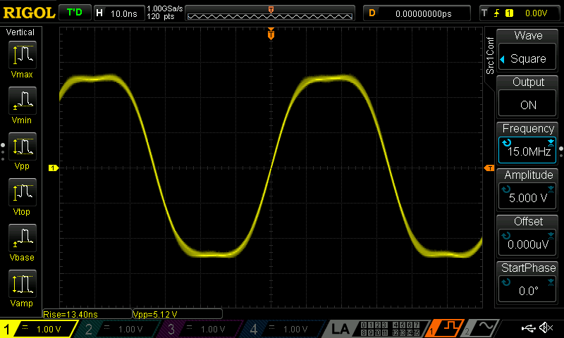
-
Hi,
Thanks for the sanity check everyone.
I have done a screenshot of my scope, I have used both channels of the signal generator, one of the channels is using a BNC cable with mini-grabbers (yellow) and one channel is using a scope probe set to x1 (blue)
The results seem wildly different, I'm assuming you really shouldn't use a scope probe for the sig gen at higher frequencies?
michaeliv, the scope I'm on is a Rigol MSO1104Z-S, im using the built in Signal Generator.
-
As a follow-up question. Is there really such a thing as a square wave?
Many people will tell you that if you combine an infinite number of sine waves you can get a square wave, but this has been proven to be incorrect. There's a good discussion on Quora: https://www.quora.com/Can-we-in-practice-exactly-reconstruct-a-square-wave-by-summing-up-sinusoidal-components.
Of course, a signal generator doesn't do this anyway. It just turns a signal on and off at a certain rate. -
Hi,
Thanks for the sanity check everyone.
I have done a screenshot of my scope, I have used both channels of the signal generator, one of the channels is using a BNC cable with mini-grabbers (yellow) and one channel is using a scope probe set to x1 (blue)
The results seem wildly different, I'm assuming you really shouldn't use a scope probe for the sig gen at higher frequencies?
michaeliv, the scope I'm on is a Rigol MSO1104Z-S, im using the built in Signal Generator.
Did you compensate the probe? -
Howard, I've tried adjusting the compensation pot on the probe and it doesn't do a great deal because the probe that's plugged into the Signal Generator on the Blue wave is set to x1
I think you are right with the rise time on the sig gen being 15ns meaning that its going to look tapered at the edges at higher frequencies. -
Hi,
Thanks for the sanity check everyone.
I have done a screenshot of my scope, I have used both channels of the signal generator, one of the channels is using a BNC cable with mini-grabbers (yellow) and one channel is using a scope probe set to x1 (blue)
The results seem wildly different, I'm assuming you really shouldn't use a scope probe for the sig gen at higher frequencies?
You just learned to not use a scope probe at 1x for high frequency signals. Check the probes documentation, it will tell you that at 1x the bandwidth is quite low compared to 10x. I have an example here where at 10x the bandwidth is supposedly more than 100 MHz while at 1x that drops to 5 MHz (!).
As others mentioned proper 50 Ohms impedance throughout, i.e. no clips, mini-grabbers or stuff, just 50 Ohms coax with 50 Ohms connectors and a 50 Ohms termination at the scope end might help (the screenshot doesn't look like that's a problem here though).
And for a 15 MHz square wave you kinda sorta need about 150 MHz analog bandwidth and about 1.5 GSa/s, otherwise even a very good signal will start to look deformed. -
And for a 15 MHz square wave you kinda sorta need about 150 MHz analog bandwidth and about 1.5 GSa/s, otherwise even a very good signal will start to look deformed.
Your other points about the probes are correct, but those points are far too simplistic.
The scope bandwidth you need is completely unrelated to a square wave's frequency; it depends only on the risetime/falltime. The traditional rule of thumb is tr=0.35/BW. Simple thought: when looking at one transition, the scope neither knows nor cares when the next transition will come along.
Secondly, the relationship between samples/s and bandwidth is also too simplistic. Many scopes have an "ETS" mode where the sample rate is much less than the signals' bandwidth; many years ago I used a 25MS/s to observe sub-nanosecond risetimes. First google result for a contemporary scope: https://www.picotech.com/library/oscilloscopes/equivalent-time-sampling -
And for a 15 MHz square wave you kinda sorta need about 150 MHz analog bandwidth and about 1.5 GSa/s, otherwise even a very good signal will start to look deformed.
Your other points about the probes are correct, but those points are far too simplistic.
The scope bandwidth you need is completely unrelated to a square wave's frequency; it depends only on the risetime/falltime. The traditional rule of thumb is tr=0.35/BW. Simple thought: when looking at one transition, the scope neither knows nor cares when the next transition will come along.
Secondly, the relationship between samples/s and bandwidth is also too simplistic. Many scopes have an "ETS" mode where the sample rate is much less than the signals' bandwidth; many years ago I used a 25MS/s to observe sub-nanosecond risetimes. First google result for a contemporary scope: https://www.picotech.com/library/oscilloscopes/equivalent-time-sampling
OK, granted, I guess that's why it's called "rule of thumb" ;-)
Of course I assume a square wave has "reasonably" (for some definition of that) steep edges, needing about enough bandwidth for the 7th to 9th harmonic to show a reasonable (...) image of the signal. Since there is a relation between maximum possible rise/fall time and base frequency of a square wave the base frequency also sets the lowest allowable bandwidth limit.
As for ETS mode, hmm, I think that's largely a (historical) kludge, although if properly implemented it should work for suitable signals. IOW - usually not.
You just can't observe a not strictly repetitive (over many periods of the timebase) signal using ETS. And if you already know that much about the signal there are only a few things left to find out about it by using a scope.
For anything non-repetitive, glitchy, not-quite-known-in-advance there is no way around having enough bandwidth and sample rate to capture the actual signal - at first go. -
And for a 15 MHz square wave you kinda sorta need about 150 MHz analog bandwidth and about 1.5 GSa/s, otherwise even a very good signal will start to look deformed.
Your other points about the probes are correct, but those points are far too simplistic.
The scope bandwidth you need is completely unrelated to a square wave's frequency; it depends only on the risetime/falltime. The traditional rule of thumb is tr=0.35/BW. Simple thought: when looking at one transition, the scope neither knows nor cares when the next transition will come along.
Secondly, the relationship between samples/s and bandwidth is also too simplistic. Many scopes have an "ETS" mode where the sample rate is much less than the signals' bandwidth; many years ago I used a 25MS/s to observe sub-nanosecond risetimes. First google result for a contemporary scope: https://www.picotech.com/library/oscilloscopes/equivalent-time-sampling
OK, granted, I guess that's why it's called "rule of thumb" ;-)
Of course I assume a square wave has "reasonably" (for some definition of that) steep edges, needing about enough bandwidth for the 7th to 9th harmonic to show a reasonable (...) image of the signal. Since there is a relation between maximum possible rise/fall time and base frequency of a square wave the base frequency also sets the lowest allowable bandwidth limit.
The second sentence is wrong, pure and simple: the transition time is independent of the period. As for the first sentence...
Er, no. Let me guess. Your background is either theoretical or audio or software; you don't appear to have used a scope for looking at medium speed logic signals (medium speed = any logic family introduced since 1980)
Very few people look at square waves; the primary place you find them is in textbooks, especially associated with introductory Fourier analysis.
Most people look at logic signals. There the key factors are signal integrity and logic value. Signal integrity requires ensuring the transition time does not violate the specs in the logic families' data sheet (valid voltages at all times, and minimum slew rate, and minimum pulse widths).
It doesn't matter if your signal transitions once per microsecond or once per year: you still need to have suitably fast edge rates. The device I was using today (a 74LVC1G14) specifies tr<=2.5ns.
It doesn't matter if your clock rate is 1MHz or 1mHz. If there is a runt pulse of a couple of nanoseconds then it can misclock or fail setup/hold times.
You would benefit from understanding Bogotin's rules of thumb http://www.edn.com/collections/4435129/3/Bogatin-s-Rules-of-Thumb especially rule 0.QuoteAs for ETS mode, hmm, I think that's largely a (historical) kludge, although if properly implemented it should work for suitable signals. IOW - usually not.
No. I explicitly referred to a contemporary scope.
Of course, if you have excessive amount of money then you can very fast sampling rates. But engineering is learning how to use your tools and - to repeat the old aphorism - do for $1 what any fool can do for $10.QuoteYou just can't observe a not strictly repetitive (over many periods of the timebase) signal using ETS. And if you already know that much about the signal there are only a few things left to find out about it by using a scope.
If only things were that simple.
Repetitive or pseudo-repetitive signals are required. Often signals can be arranged to be repetitive. If not then you can still get important information from pseudo repetitive signals. For example, eye diagrams are also a current technique that won't disappear soon - especially with bit rates >1Gb/s.QuoteFor anything non-repetitive, glitchy, not-quite-known-in-advance there is no way around having enough bandwidth and sample rate to capture the actual signal - at first go.
It certainly helps, but eventually you will run into circumstances where that isn't sufficient; at that point you have to become more creative in how you use your tools. You might as well use the same techniques at other times. -
And for a 15 MHz square wave you kinda sorta need about 150 MHz analog bandwidth and about 1.5 GSa/s, otherwise even a very good signal will start to look deformed.
Your other points about the probes are correct, but those points are far too simplistic.
The scope bandwidth you need is completely unrelated to a square wave's frequency; it depends only on the risetime/falltime. The traditional rule of thumb is tr=0.35/BW. Simple thought: when looking at one transition, the scope neither knows nor cares when the next transition will come along.
Secondly, the relationship between samples/s and bandwidth is also too simplistic. Many scopes have an "ETS" mode where the sample rate is much less than the signals' bandwidth; many years ago I used a 25MS/s to observe sub-nanosecond risetimes. First google result for a contemporary scope: https://www.picotech.com/library/oscilloscopes/equivalent-time-sampling
OK, granted, I guess that's why it's called "rule of thumb" ;-)
Of course I assume a square wave has "reasonably" (for some definition of that) steep edges, needing about enough bandwidth for the 7th to 9th harmonic to show a reasonable (...) image of the signal. Since there is a relation between maximum possible rise/fall time and base frequency of a square wave the base frequency also sets the lowest allowable bandwidth limit.
The second sentence is wrong, pure and simple: the transition time is independent of the period.
Not really. What I meant is the following: the sum of rise and fall time can't be larger than the period of the square wave. At the limit it will already be a triangle or sawtooth.Er, no. Let me guess. Your background is either theoretical or audio or software; you don't appear to have used a scope for looking at medium speed logic signals (medium speed = any logic family introduced since 1980)
What I currently do to earn money is software. What I got an education in - way back when - is electronics. So there. ;-)Very few people look at square waves; the primary place you find them is in textbooks, especially associated with introductory Fourier analysis.
Most people look at logic signals. There the key factors are signal integrity and logic value. Signal integrity requires ensuring the transition time does not violate the specs in the logic families' data sheet (valid voltages at all times, and minimum slew rate, and minimum pulse widths).
Everybody knows that strictly speaking a square wave is a mathematical abstraction not existing in the real world. At least people should know.
That doesn't dissuade anybody from talking about square waves in the real, physical world if the signal in question is close enough to the mathematical ideal.
[...]QuoteYou just can't observe a not strictly repetitive (over many periods of the timebase) signal using ETS. And if you already know that much about the signal there are only a few things left to find out about it by using a scope.
If only things were that simple.
Repetitive or pseudo-repetitive signals are required. Often signals can be arranged to be repetitive. If not then you can still get important information from pseudo repetitive signals. For example, eye diagrams are also a current technique that won't disappear soon - especially with bit rates >1Gb/s.
OK, but as far as i'm aware not that many people actually deal with that kind of bitrates (not even in a professional context), and I didn't mean to talk about measuring that kind of high speed signals.
Certainly the OP didn't talk about Gbps signals either, so information about measuring these is unlikely to be helpful to him, at least in the short/medium term.
[...] -
And for a 15 MHz square wave you kinda sorta need about 150 MHz analog bandwidth and about 1.5 GSa/s, otherwise even a very good signal will start to look deformed.
Your other points about the probes are correct, but those points are far too simplistic.
The scope bandwidth you need is completely unrelated to a square wave's frequency; it depends only on the risetime/falltime. The traditional rule of thumb is tr=0.35/BW. Simple thought: when looking at one transition, the scope neither knows nor cares when the next transition will come along.
Secondly, the relationship between samples/s and bandwidth is also too simplistic. Many scopes have an "ETS" mode where the sample rate is much less than the signals' bandwidth; many years ago I used a 25MS/s to observe sub-nanosecond risetimes. First google result for a contemporary scope: https://www.picotech.com/library/oscilloscopes/equivalent-time-sampling
OK, granted, I guess that's why it's called "rule of thumb" ;-)
Of course I assume a square wave has "reasonably" (for some definition of that) steep edges, needing about enough bandwidth for the 7th to 9th harmonic to show a reasonable (...) image of the signal. Since there is a relation between maximum possible rise/fall time and base frequency of a square wave the base frequency also sets the lowest allowable bandwidth limit.
The second sentence is wrong, pure and simple: the transition time is independent of the period.
Not really. What I meant is the following: the sum of rise and fall time can't be larger than the period of the square wave. At the limit it will already be a triangle or sawtooth.Er, no. Let me guess. Your background is either theoretical or audio or software; you don't appear to have used a scope for looking at medium speed logic signals (medium speed = any logic family introduced since 1980)
What I currently do to earn money is software. What I got an education in - way back when - is electronics. So there. ;-)Very few people look at square waves; the primary place you find them is in textbooks, especially associated with introductory Fourier analysis.
Most people look at logic signals. There the key factors are signal integrity and logic value. Signal integrity requires ensuring the transition time does not violate the specs in the logic families' data sheet (valid voltages at all times, and minimum slew rate, and minimum pulse widths).
Everybody knows that strictly speaking a square wave is a mathematical abstraction not existing in the real world. At least people should know.
That doesn't dissuade anybody from talking about square waves in the real, physical world if the signal in question is close enough to the mathematical ideal.
[...]QuoteYou just can't observe a not strictly repetitive (over many periods of the timebase) signal using ETS. And if you already know that much about the signal there are only a few things left to find out about it by using a scope.
If only things were that simple.
Repetitive or pseudo-repetitive signals are required. Often signals can be arranged to be repetitive. If not then you can still get important information from pseudo repetitive signals. For example, eye diagrams are also a current technique that won't disappear soon - especially with bit rates >1Gb/s.
OK, but as far as i'm aware not that many people actually deal with that kind of bitrates (not even in a professional context), and I didn't mean to talk about measuring that kind of high speed signals.
You might be surprised. Surprisingly little has changed in the past 2 or three decades, except for things becoming smaller, faster, cheaper. But nowadays even run-of-the mill logic and FPGAs are multi-gigabit/s per pin, and the aggregate bandwidth is stunning.
Two areas that have changed significantly are nanopower devices/systems, and the sampling rate of digitisers/scopes. Are you aware that you can buy a 160GS/s scope? (I looked last year; there may be faster machines available this year.QuoteCertainly the OP didn't talk about Gbps signals either, so information about measuring these is unlikely to be helpful to him, at least in the short/medium term.
The principles and misapprehensions are the same at any speed.
-
Are you aware that you can buy a 160GS/s scope?
My bank account would like to respectfully disagree with you. -
That's what bank loans are forAre you aware that you can buy a 160GS/s scope?
My bank account would like to respectfully disagree with you.
-
For the OP, here's a thread on square waves from last year:
https://www.eevblog.com/forum/testgear/show-us-your-square-wave/
-
As a quick optimisation hack: If you have a crappy pulse gen or function generator, you can improve the rise time by piping the output via a few gates in parallel from a 74AC14 schmitt inverter array properly terminated close to the scope. 1-2ns edges on them. That looks more like the real fourier series output for a square (is there such a thing?) wave as well: ringing. This trick has been around since the dark ages.
I await the day I find a cheap Tek 7000 1GHz mainframe... -
As a quick optimisation hack: If you have a crappy pulse gen or function generator, you can improve the rise time by piping the output via a few gates in parallel from a 74AC14 schmitt inverter array properly terminated close to the scope. 1-2ns edges on them. That looks more like the real fourier series output for a square (is there such a thing?) wave as well: ringing. This trick has been around since the dark ages.
Personally I use 3*(74LVC1G14+130ohms) in parallel. On my Tek485 (350MHz nominally, but surprisingly good to 600MHz) I can see ~900ns risetimes. Indirect measurements of the spectrum lead me to believe the risetime is nearer 600ps. -
That's a fast edge! I'm maxed out on a 465B at 100MHz and I can measure ~1.5ns off an 74AC14. I would love to use 74LVC1G14 but I can't see the damn things
-
That's a fast edge! I'm maxed out on a 465B at 100MHz and I can measure ~1.5ns off an 74AC14. I would love to use 74LVC1G14 but I can't see the damn things
That's what head-mounted visors are for
Here are some oscillograms with my 485.
The reference is the 485's own cal out, which is a respectable ~1ns risetime although only 500mVpp.
The 3*(74LVC1G14 + 130ohms) is the most repeatable result, with ~900ps risetime and a moderate overshoot.
The 3*74LVC1G14 driving 50 ohms is pretty respectable too (and twice the amplitude). OTOH, when driving a scope input 1Mohm // 20pF the results merely show why signal integrity is an important topic.
Using a 1.5GHz low-impedance Z0 probe, an HP10020a with a spear ground, shows pretty respectable results for an ad-hoc connection. The single output is perfectly acceptable, but paralleling three gives too much "oomph" The source of the 500MHz ringing is unclear; I would expect probe resonances to be around 1GHz (<1pF, 25mm=25nH).
EDIT: the obvious test is to use the low-impedance probe to observe the 3*(74LVC1G14 + 130ohms) signal output. The two traces are identical within the limits of the match of the two oscilloscope input channels. Conclusion: the ringing is a real artefact, not an artefact of the probe.
-
Cool stuff.
Is that 50 ohm termination inside the 485?
Quite surprised to see that level of ringing on a Z0 probe with spear. TBH at that level because my crappy old Tek probes taper off at about 70MHz, and I'm too cheap to buy some nice ones, I built my own probe with a bit of quality RG58U and a couple of hand picked resistors and soldered it in circuit. No internal termination on my 465B though. Worked like a dream however
-
Is that 50 ohm termination inside the 485?
Yes it is, and all the better for it Presumably Tek learned from the HP1740a - and improved on it by disconnecting the 50ohms in the event of an overload.QuoteQuite surprised to see that level of ringing on a Z0 probe with spear. TBH at that level because my crappy old Tek probes taper off at about 70MHz, and I'm too cheap to buy some nice ones, I built my own probe with a bit of quality RG58U and a couple of hand picked resistors and soldered it in circuit. No internal termination on my 465B though. Worked like a dream however
So am I. I think the 3*CMOS may be partially due to a longer track (<2cm) than desirable. Maybe I'll chop the track and see if it makes a difference. The other possibility is that a 100nF 0603 for each gate isn't sufficient decoupling.
OTOH, there's no such issue with the 1*CMOS, and the ringing is still there at the same frequency, albeit lower amplitude.
Hence I suspect it is the CMOS output being agggressive. -
For the OP, here's a thread on square waves from last year:
https://www.eevblog.com/forum/testgear/show-us-your-square-wave/
Thanks for this, exactly what I was looking for, plenty of images from other peoples scopes there that shows exactly what I was experiencing.
Also, thanks to everyone else, looks like a couple of people had an ahem "interesting" discussion around the thread.
Guess my next research for a couple of hours is Fourier Series.
