-
Getting a stable 10's of pA measurement is an excellent achievement. A lot of things have to be "just so" for that to happen.
-
Yes, some way of logging the readings is probably the way to go. Maybe your next investment could be a bench DMM with logging?
I think I'll use an arduino to take picoamp measurements at regular intervals and then flash an LED to broadcast the information after each measurement is taken. I'm guessing I'll read the optical telementry by drilling a tiny hole in the secondary shielded enclosure. Once read, I'll immediately plot it and/or enter it into a timebase database of some kind.
So, I'll need to find some easy to use ploting/charting/graphing library. I used to use plot.ly, which I liked a lot, but it has gone corporate and I'm not sure how much of it can be accessed anymore. -
Don't forget, an Arduino also radiates RF simply because it runs at 16MHz and does a lot of fast switching. It could play havoc if it is near a sensitive measurement. Depending on how sensitive the measurements you are trying to make are, it might be best to keep things analog inside the experiment's shield, and convert to digital outside? -
It's starting to look as though the noise is getting under much better control. Here are some scope shots I took, at different frequencies, of me sending a sinusoid of between 0 and 500 millivolts to the picoammeter (which, at least a low frequency, should correspond to between 0 and 500 picoamps).
0.01Hz:
0.1Hz:
1Hz:
Obviously the effects of limited bandwidth are becoming apparent.
Adjusting the same 1Hz scope capture to show more detail:
-
10Hz:
At 10Hz most of the detail is almost gone.
-
Don't forget, an Arduino also radiates RF simply because it runs at 16MHz and does a lot of fast switching. It could play havoc if it is near a sensitive measurement. Depending on how sensitive the measurements you are trying to make are, it might be best to keep things analog inside the experiment's shield, and convert to digital outside?
I just now did the experiment. I plugged in an Arduino Uno right next to it and even powered it with a buck converter, hoping to create a worst case. I put it right next to the picoammeter, and it didn't perturb the measurements at all. Same thing with an Arduino Mega2560: no effect. It seems that high frequencies don't bother the picoammeter. Or, maybe it's their low power. Either way, all of that is really good news!
Apparently it's the opposite with lower frequencies though. That 60Hz AC frequencyis quite visible if I turn the oscilloscope up to 10mv/div. I need to do further isolation and removal of other SMPS's from the area though before I can be sure the 60hz noise is coming from the Rigol and not something else. I would think that a Rigol would be pretty well designed to avoid giving off that kind of noise, so I suspect it may not be to blame. With the bad SMPS's that I've already removed, they could affect the picoammeter measurements even at several feet away.
--------------------------
In the scope shots I posted just above, it's clear that the swing of the output voltage on the picoammeter is getting reduced as frequency increases. This is not unexpected, given what Gyro said about the bandwidth of this design. Question: Is the picoammeter still faithfully measuring and reporting the amount of picoamps passing through it on the way to ground while the bandwidth limitations are especially noticeable, or does the picoammeter lose accuracy under those conditions? What I mean is, there seem to be three possible cases: (1) are the picoamps being throttled but still accurately reported, or (2) are the picoamps actually the same (unchanged) and simply not accurately reported, or (3) are the picoamps both throttled and not accurately reported? i.e. which of the 3 cases is the reality? I can't answer the question experimentally without an accurate higher bandwidth picoammeter, which I don't have. -
Getting a stable 10's of pA measurement is an excellent achievement. A lot of things have to be "just so" for that to happen.
The credit goes to Gyro for coming up with a good design, and the credit goes to you for figuring out that Gyro had a worthwhile design and then suggesting it!
-
Cool scope shots! Do you always work this fast?
Hard to say if the picoamps are being affected as well as just the reading. It sounds plausible that it could, since we are depending on a virtual ground created by the op amp inside the box.
What is the max number of picoamps that the Gyro meter can display? - maybe there is an overlap with the low range of the uCurrent? (I got it down to about 500pA on AC, might have got lower if I had an amplifier to boost the signal coming out of it).
Lastly, consider that even if the picoammeter may be immune to RF, that may not be true of the thing you are measuring inside the experiment's enclosure?
-
Getting a stable 10's of pA measurement is an excellent achievement. A lot of things have to be "just so" for that to happen.
The credit goes to Gyro for coming up with a good design, and the credit goes to you for figuring out that Gyro had a worthwhile design and then suggesting it!
Thank you @NeverDie. Whilst the 'Gryo Picoammeter' has a nice ring to it, I can't claim any credit for transimpedance amplifiers, bias networks, air wiring, or even relying on suitably protected internal protection diodes (maybe noticing that they are bootstrapped on the 662 though). Putting them all together in a screened box basically comes down a bit of attention to detail and conservative engineering, which is always good to strive for.
P.S. Agreed, really nice scope captures! I wish I'd done some work on characterising the AC performance myself. Although you don't want to mess with unnecessarily soldering Polystyrene capacitors, there's probably a sweet spot for being able to externally resolve the wanted signal, while achieving maximum frequency response. It probably varies from case to case though. -
Getting a stable 10's of pA measurement is an excellent achievement. A lot of things have to be "just so" for that to happen.
The credit goes to Gyro for coming up with a good design, and the credit goes to you for figuring out that Gyro had a worthwhile design and then suggesting it!
Thank you @NeverDie. Whilst the 'Gryo Picoammeter' has a nice ring to it, I can't claim any credit for transimpedance amplifiers, bias networks, air wiring, or even relying on suitably protected internal protection diodes (maybe noticing that they are bootstrapped on the 662 though). Putting them all together in a screened box basically comes down a bit of attention to detail and conservative engineering, which is always good to strive for.
P.S. Agreed, really nice scope captures! I wish I'd done some work on characterising the AC performance myself. Although you don't want to mess with unnecessarily soldering Polystyrene capacitors, there's probably a sweet spot for being able to externally resolve the wanted signal, while achieving maximum frequency response. It probably varies from case to case though.
Just wanted to say impressive results and very nice teamwork. Hope at some point when you guys think the time is right or as you go you might add some summarizing thoughts on this in way that includes a blend of high level fundamental principles for people just getting started with very low current measurements and your key learnings for more advanced measurers. fwiw, this endeavor reminds me a little of other “time nut, volt nut, and other nut” threads and endeavors in which people are pushing the boundaries of what can be cost-effectively measured with respect to pretty small and low level signals. It’s very much a testament to collaborative ingenuity.
-
+1
What is the max number of picoamps that the Gyro meter can display?
Maybe @Gyro can comment?
As for noise, what I'm currently experiencing is comparable to the sort of stuff Dave Jones comments about toward the end of:
where he blames his noise on things like long test probe wires and environmental noise. He relegates it to a topic for another video and does nothing about it. i.e. it really is good enough for Australia!
So, with that as the acceptance criteria, I deem this build of the picoammeter as finished.
Getting rid of the remaining noise will be the topic of a new build. And I think maybe including a BNC connector might be a step in that direction. What do you guys think? The tinyCurrent has one as one of its main selling points: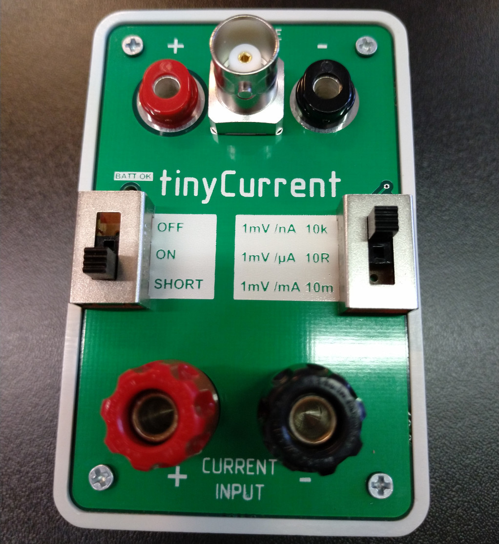
And their github has some captured images showing a reduction in noise by using it rather than the banana plugs.
-
+1
What is the max number of picoamps that the Gyro meter can display?
Maybe @Gyro can comment?
It can do at least +/- 2.5nA (+/- 2.5V output) based on the 9V battery discharge curve (at the battery replacement point). With a fresh battery it will do at least +/- 4nA. -
Just wanted to say impressive results and very nice teamwork. Hope at some point when you guys think the time is right or as you go you might add some summarizing thoughts on this in way that includes a blend of high level fundamental principles for people just getting started with very low current measurements and your key learnings for more advanced measurers. fwiw, this endeavor reminds me a little of other “time nut, volt nut, and other nut” threads and endeavors in which people are pushing the boundaries of what can be cost-effectively measured with respect to pretty small and low level signals. It’s very much a testament to collaborative ingenuity.
Agreed, these guys (NeverDie here and SilverSolder in his other thread) are achieving some very good results, given the very basic tools for the job.
You could also have a look at the original Picoammeter thread, which has some useful insights from the like of Alex Nikitin... https://www.eevblog.com/forum/projects/picoammeter-design/
... but it is most definitely worth downloading 'the bible' - the Tektronix / Keithley Low Level Measurement Handbook, which is conveniently free and is a very easy read, with lots of diagrams:
https://www.tek.com/document/handbook/low-level-measurements-handbook
Edit: The thread title could do with a bit of tweaking by now though. -
You're right. I just now renamed the thread.
-
So, I think maybe using an isolated BNC jack for the output:

and a non-isolated BNC jack for the input (so that it immediately grounds to the enclosure) might be the way to go for build #2.
This way, using coax cables, hopefully the noise, especially on the input side, will be reduced.
If it turns out you want banana plugs in some situation, then there are always BNC-to-banana-plug adapters that you could plug in.
I'm hoping this, together with using oscilloscope probes, will maybe overcome some of the "long wire" noise problems. Plus, it would leverage oscilliscope probes and wiring, which you would already have.
Or, is there something even better that could be used instead? e.g. don't some oscilliscope probes have even extra shielding of some kind? -
You can probably dispense with the 1k resistor on the +Ve output and use a non-isolated BNC for the output too. I put the resistor there as a precaution but it shouldn't affect stability as long as the one on the -Ve terminal (centre pin) is still present.
-
These banana-to-BNC adaptors are super handy - no home is complete without them!
-
Are 50-ohm connectors the right choice? From what I can tell, it seems the most common....
-
You can probably dispense with the 1k resistor on the +Ve output and use a non-isolated BNC for the output too. I put the resistor there as a precaution but it shouldn't affect stability as long as the one on the -Ve terminal (centre pin) is still present.
Should I use a shorting cap on the input BNC when doing the zero calibration on the picoammeter?
Or should I use a 50 ohm BNC terminator instead?
-
IIRC I didn't have serious noise problems when using a normal scope probe. The circuit was mounted in a conductive box with a small hole for the probe cable, the box was grounded to the probe's alligator clip in some random place.
BNC should work too. You don't need to care about wave impedance, it has nothing to do with connector resistance (which is close to zero) or anything like that. Just take 50Ω.
You also want shielding around the circuit whose current you are measuring, not sure if you have that. I simply put everything except the scope in one box.In the scope shots I posted just above, it's clear that the swing of the output voltage on the picoammeter is getting reduced as frequency increases. This is not unexpected, given what Gyro said about the bandwidth of this design. Question: Is the picoammeter still faithfully measuring and reporting the amount of picoamps passing through it on the way to ground while the bandwidth limitations are especially noticeable, or does the picoammeter lose accuracy under those conditions? What I mean is, there seem to be three possible cases: (1) are the picoamps being throttled but still accurately reported, or (2) are the picoamps actually the same (unchanged) and simply not accurately reported, or (3) are the picoamps both throttled and not accurately reported? i.e. which of the 3 cases is the reality? I can't answer the question experimentally without an accurate higher bandwidth picoammeter, which I don't have.
(2) or (3), depending on the speed of the opamp.
The thing about the capacitor is that it has low impedance at high frequencies, so tiny swings of the opamp's output produce the desired input AC current and are almost invisible on the output. So you don't see it, but the current flows, as long as the opamp is fast enough to produce it and maintain effective virtual ground on the input node. -
So, if it really is #2, then it seems like there should exist a way for a computer to reconstruct and plot what the true current flow is. Is there a commonly used computer program for doing that?
--------------------------------
Edit1: I ordered some BNC connectors, and they may arrive as early as tomorrow. I'm debating whether to upgrade the current picoammeter or to make a new one. If I make a new one, then I can compare results, and it will be easier to tell how much improvement (or not) the BNC connectors make, as well as any other upgrades anyone wants to suggest.
Anyhow, I ordered enough parts so that I can both make a new picoammeter and upgrade the "old" one if the upgrades do yield improvement. For example, although it's overkill for my current needs, it might be fun to see if we can accurately measure single digit picoamps.
Therefore, I hereby solicit suggestions for further improvements, whether relating to noise or anything else.
Edit2: For the next build I plan to use a tilt switch instead of a reed switch to turn the picoammeter on-off:
https://smile.amazon.com/gp/product/B07MR88MQL/ref=ppx_yo_dt_b_asin_title_o00_s00?ie=UTF8&psc=1
I'll simply turn the picoammeter upside down when not in use. No magnet required! -
It's easier not to have the bandwidth limit in the first place. The LMC662 datasheet discusses how much capacitance is required for the amplifier to work correctly and remain stable; IIRC it is much less than people typically used in the picoammeter thread. The reason for the bandwidth limit was to limit noise and make it easier to measure average DC current with high resolution.
-
You can probably dispense with the 1k resistor on the +Ve output and use a non-isolated BNC for the output too. I put the resistor there as a precaution but it shouldn't affect stability as long as the one on the -Ve terminal (centre pin) is still present.
Should I use a shorting cap on the input BNC when doing the zero calibration on the picoammeter?
Or should I use a 50 ohm BNC terminator instead?
You're right, 50R BNCs are most common and a sensible choice.
No, never use a shorted input or terminator to zero the picoammeter - it won't do any damage, but the output will go to one rail and stay there (it basically becomes a voltage comparator circuit, biased by the opamp offset voltage). The rule is to zero voltmeters with a shorted input and ammeters with an open input.
Connect the input to the -Ve output to zero the 662 offset voltage. When you remove the link, it will then just read the input bias current (hopefully single digits fA). If you want to shield the input to make this measurement as stable as possible, then either put something across the end of the BNC - copper tape, coin, BNC plug with centre pin removed. -
Haven't read the thread yet but thought it might be worth mentioning Dave did a video on his Keithley 480 Picoammeter and shows the stability just on an open bench at 23mins in. I brought one a while back as well that I got round to repairing a few years ago.
-
Can desktop ESD matting be used on the floor as well? I certainly hope so, as I just now purchased a 32 feet long x 36" wide 2-layer roll of it that was on discount, so I hope to use it for both surfaces. The conductive side is made out nitrile butadiene rubber (NBR) and the dissipative side is some kind of semi-gloss material. Hakko brand, so I presume it's quality.
I would have gone for natural rubber, but it was only available in a hideous green color, whereas this stuff is neutral gray. I just hope it can withstand me rolling my chair around on top of it. If it's capable of that, then this will be a major upgrade toward getting rid of the static influences on the picoammeter measurements.
Speaking of Hakko, I notice they also sell what they describe as a static eliminating fan (?!): http://www.hakko.com/english/products/hakko_fe510_feature.html#productNav
Anyone here tried or using such a thing, and does it work? It looks as though, at present, it's only being sold in Japan and Asia.