Does the Owon XDS3202A Oscilloscope use a true 14bit converter?
Yep. Will not buy this thing. Not in a 1000 years.
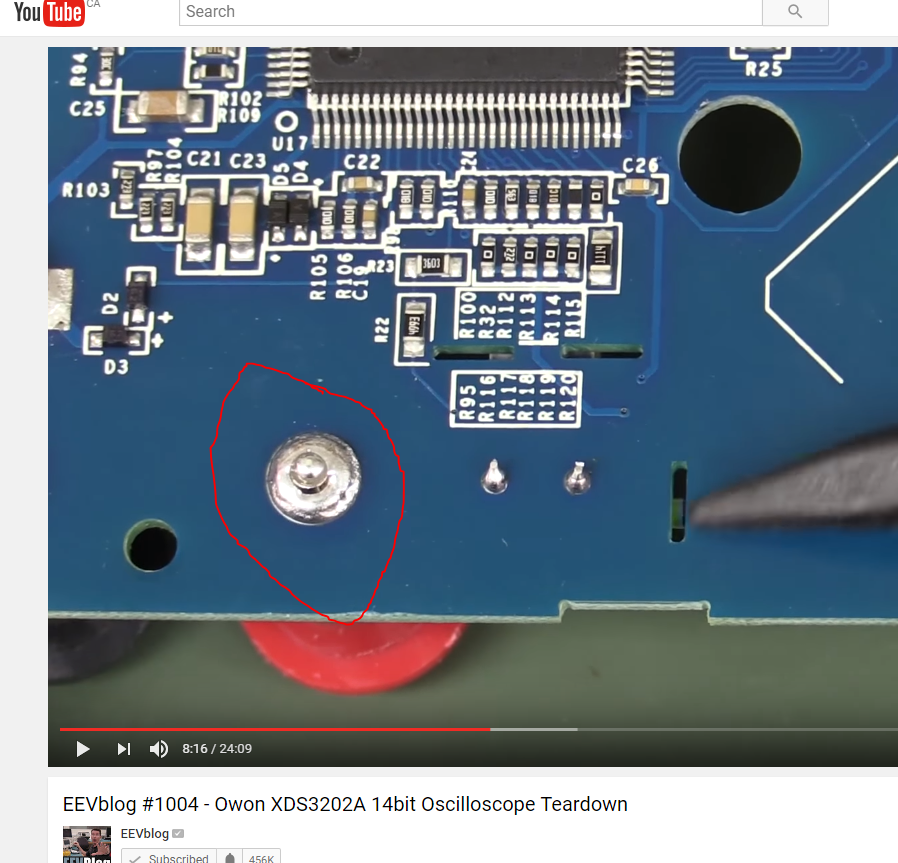
Is it me, or is this a really really bad solder connection...
Am I nuts, or is that thing on the front panel above the buttons an IR window?
That multimeter board is just waiting to die of a mild static shock. Or Joe's grill igniter. Flimsy Semiconductor..
Not just the last one. Only the first one would get a "pass" from me. But the last two ones are awful!

Also their "cooling" solution is laughable...
I wonder if they hope to get better wi-fi by coupling the antenna to the mains?
I'm fascinated. What is the purpose of this exposed gold?
Why gold? Why exposed?
Hi Dave, you said that the fuse is missing on the PSU board but I think it is in the IEC connector assy. though.
I wonder if they hope to get better wi-fi by coupling the antenna to the mains?
That was my first thought. No idea though.
I know some one in liliput, company that owns owon (sort of o - we won)

their research is very small and poor

no review or quality checks
.. if you get it working .. you are a champ

but I wonder how they have survived so long. They do have a market and somehow they manage to sell a large number of these poorly designed oscilloscopes
Also their "cooling" solution is laughable...
Only if it doesn't do the job.... don't judge a book by it's cover. Having the fan deep inside the case probably reduces the noise a lot so the location of the fan may not be so bad after all.
Sticking the Wifi antenna to the mains input is probably the easiest way to get it far from the metal parts without attaching it to the back shell.
ENIG plating, the rest has solder paste on top of it
I'm fascinated. What is the purpose of this exposed gold?
Why gold? Why exposed?
The chain of vias with exposed gold could be a place where the though they might need to add extra shielding. For a first version and a not so price sensitive board this might be acceptable.
The overall power consumption is not that high. So the cooling might be good enough. I agree that air flow is a little strange.
The DMM part at the back it rather strange - at least a simple 20 mm fuse for the lower current range(s) would be a big plus. This is especially important, as current readings might be an important function - you can read voltages with the scope already. Having an unprotected 10 A or so range is not that bad - not a good instrument for high power circuits anyway. However selecting the 10/20 A range with a different input can be tricky when you can not see the connectors. This way I would prefer a cheap $10 DMM as a second unit - easy to replace if the shunt is blown and usually a more intuitive UI. It is only possible data logging you don't get with the cheap ones - but who knows if the SW supports this here. An added DMM function would be nice if fast (e.g. audio speed) - like usable as a slow 3rd channel.
Does one really need or even want Wifi on a low noise scope. I would be afraid it could be more trouble with interference than good.
Similar the VGA (or similar) output. Generally it is good to have one at a scope. However why add a extra chip for a portable instrument with battery option. Good SW support for LAN would be likely as good.
I don't think that lack of fuses in the multimeter is a problem.
There's plenty of input 'protection' in the form of making it really inconvenient to move the leads to current measurement position. So much so that I expect people will just use a real multimeter for that. Owon saved us a few cents there.

The VGA output is puzzling. Is there really anybody who'd want that?

Maybe the VGA output is for a really specialist use like Chinese electronic assembly lines and OWON are hoping to cash in on that.
(In fact the combination of features on this device is just so weird that I suspect the entire 'scope is an attempt to cash in on one particular, specialist market).
I don't think that lack of fuses in the multimeter is a problem.
Put any unfused mA meter in a student lab and get the stopwatch ready to time how quickly it will be destroyed.
Put any unfused mA meter in a student lab and get the stopwatch ready to time how quickly it will be destroyed.
Students did not use to be this dumb, my first day at secondary school a teacher canned every one of us boys in his first class. Latter that afternoon a class mate put his feet up on a tool rack in a shop class. Old guy grabbed his cane and gave us another lesson in the use of good judgment. I'm 100% confident that had we been fortunate enough to have the use of a meter in class that it would have survived the year no problem.
I don't think that lack of fuses in the multimeter is a problem.
There's plenty of input 'protection' in the form of making it really inconvenient to move the leads to current measurement position. So much so that I expect people will just use a real multimeter for that. Owon saved us a few cents there.
The VGA output is puzzling. Is there really anybody who'd want that?
Maybe the VGA output is for a really specialist use like Chinese electronic assembly lines and OWON are hoping to cash in on that.
(In fact the combination of features on this device is just so weird that I suspect the entire 'scope is an attempt to cash in on one particular, specialist market).
VGA output is entirely reasonable - it's the composite that's really strange (assuming that's what that yellow phono/RCA socket is).
Owon have "previous" for terrible DMM designs. I really can't see how anyone thought it made any sense to include one in a scope like this, less so with the inputs on the back.
I really can't see how anyone thought it made any sense to include one in a scope like this, less so with the inputs on the back.
My hypothetical:
- New student graduate suggested adding a multimeter
- Marketing says it's a great idea
- Executives say "Do it"
- Management says put it on the back, because re-tooling for the front panel is outside the budget
- Engineer shakes their head and does what they're told.
VGA output is entirely reasonable - it's the composite that's really strange (assuming that's what that yellow phono/RCA socket is).
Maybe because the DAC chip can do both?
The CH7026 seems to be a rather advanced video encoder: It has build in 16MBit SDRAM for framerate conversion, a video scaler and other stuff.
But that does not answer why they have used this chip. It doesn't look cheap and they could have used a much cheaper video DAC connected in parallel to the TFT data bus outputting the same 800x600 image.
It looks like they wanted a good quality composite video output for any reason.
I don't think that lack of fuses in the multimeter is a problem.
Put any unfused mA meter in a student lab and get the stopwatch ready to time how quickly it will be destroyed.
I once did a "bring your meter" day at Arduino club and there wasn't a single intact fuse. Not one.
It doesn't help that they usually show a number on screen when the fuse is blown. Most of them assumed the meter was broken or something.
It doesn't help that they usually show a number on screen when the fuse is blown. Most of them assumed the meter was broken or something.
You could almost incorporate that right there in some meters as a safety feature for the novice users, should a multimeter be turned on and a fuse blown then an internal counter would be incremented, when the count reaches three the meters display should scroll something like
The user of this meter is a dickhead.


Just looked up the NEC UD2-4 relay at Digikey. Twelve types. No stock. Photo shows NEC but the manufacturer is listed as Kemet.
