The keypad interface is probably not any reasonable long reach interface, but straight TTL-level I2C or something similar. Running TTL-level (I2C or otherwise) signals across long runs of some dodgy cable seems to be quite popular in alarm systems. I had even seen board marked something like "Remote zone extender" (in the same box there was bunch of random DSC boards, but I'm not sure if this particular one was DSC-branded) that was essentially 7805+PCF8574 with pins broken out to screw terminals.
The keypad interface is probably not any reasonable long reach interface, but straight TTL-level I2C or something similar. Running TTL-level (I2C or otherwise) signals across long runs of some dodgy cable seems to be quite popular in alarm systems.
Yes, must be single ended, otherwise 4 terminals would be needed for clock and data.
Seems crazy!
I think this is potentially serious issue, and I have contacted Ness about it.
FYI, Ness responded within minutes and it has gone to R&D for investigation.
I think this is potentially serious issue, and I have contacted Ness about it.
FYI, Ness responded within minutes and it has gone to R&D for investigation.
Glad to see they are taking that issue very seriously. I could imagine what could happen if those flames could potentially ignite other materials in the panel box. We techs often leave wiring lists / diagrams on paper in those panel boxes for any troubleshooting needed in the future.

Glad to see they are taking that issue very seriously. I could imagine what could happen if those flames could potentially ignite other materials in the panel box. We techs often leave wiring lists / diagrams on paper in those panel boxes for any troubleshooting needed in the future.
Yes, paper is very common inside panels like this, behind the front panel only inches from the board.
I think this is potentially serious issue, and I have contacted Ness about it.
FYI, Ness responded within minutes and it has gone to R&D for investigation.
Glad to see they are taking that issue very seriously. I could imagine what could happen if those flames could potentially ignite other materials in the panel box. We techs often leave wiring lists / diagrams on paper in those panel boxes for any troubleshooting needed in the future.
While they're at it, maybe they can change the cover photo on the D16 User Manual.
The manual has a cover photograph of the board posing in exactly the position that Dave warns against.
https://www.bensecurity.com.au/docs/D16_user_rev4.5.pdf
Just one of those odd quirks - right after Dave posts this video, one of my friends posts this link which happens to illustrate how you'd deal with the same problem affecting a slightly larger section of board:
http://home.comcast.net/~rburn/PCB-rework/
That was an interesting video again, as always.

Dave mentioned that the sensor inputs have to be terminated with a 2.2k resistor. I don't know if you guys think that it's wrong to post public about such ideas, but it set me thinking how such a sensor could be deactivated.

One could try to remove the isolation of the two sensor wires with a knife (one cable just once, the other one at two spots). Then he could connect a amp-meter between the cuts on the one wire, cut the wire between and add a volt-meter between the two wires. Through the current and voltage he could calculate the resistor, that is needed to terminate the sensor input.
Then he could place a high-value (like 100*R) potentiometer (set to 0 Ohm) in the cut wire and remove the amp-meter. Also he would have to add a potentiometer in series with a resistor of the calculated value between the two wires (parallel to the sensor-input connections), while the potentiometer has, again, a high value and is set to max. R this time.
Then the potentiometers could be adjusted - keeping an eye on the voltmeter - so that at the end the sensor is completely isolated and instead of it a resistor terminates the sensor input connections.
PS: He could of course also be she

The resistor values are commonly known, just you can either use a 3k3 resistor for a single zone, or use a pair of resistors if you are splitting zones ( which is a pain to troubleshoot) of 3.74k and 6.98k. From the outside you do not know which system has been selected for the install, and if you get it wrong the alarm will activate. The window on the comparator in the MCU is very small.
http://www.interlogix.com/_/assets/library/I-NX8E-IM%20Rev%20C%20Installation%20Manual.pdfInstall an resistor values are page 8.
Common in alarm systems to make sure the wiring is not accessible in any case, and often the installers are lazy and install the resistors in the panel, as opposed to the correct method of putting them in the actual sensors.
Dave, you forgot the links to this thread In the youtube description and on the eevblog.com post. also for repair I'd make up a daughter board and completely bypass the burned section. Maybe see if Ness will swing a replacement board your way for reporting a potentially life-threatening problem. (the board looks like the cost comes from low production volumes)
So if you mix charred pcb with liquid soldermask it turns low R 
That was my thought also.
Surely in practice this wouldn't be economical to repair.
However if it must be repaired and given the depth of burn damage I'd grind out all the damaged substrate including the tracks.
Then I'd use a compatible filler to reinforce the remaining board to the same thickness as there is a mounting hole at the corner. Then I'd create a small board to bond over the repaired substrate to mount the missing components and link to the existing connections.
How would you solve the problem if the unit MUST be repaired?
Hi Dave

Had a similar idea and never tried:
I considered, etching and drilling the section from suitable clad board and grafting into the damaged board.
Bond with the correct epoxy, chamfer the edges of "hole" and "graft" to key to each other, perhaps re-enforce with glass tape.
Or possibly re-lay grp straight on the board to repair (obviously need releasable former).
Never did try, and really am unaware of the correct materials.
You guys should use Ademco/Honeywell galaxy over in Aus
You guys should use Ademco/Honeywell galaxy over in Aus
I agree, I've been using those Ademco(now bought by Honeywell) panels for over 20 years and they are rock solid reliable.
FYI, I've been invited to Ness next Tuesday. Will hopefully get some video.
FYI, I've been invited to Ness next Tuesday. Will hopefully get some video.
they might even give you a new board for free
Missed those vids on PCB repair earlier, doh!
Why did the Russian guy cut the PCB? (no it's not a lead-in for a two line gag!)
hey, check this out:
http://hackaday.com/2014/11/13/extreme-repair-of-a-burnt-pcb/there is a guy there who made extreme repair to his amplifier board of his JBL L8400P subwoofer,
he had a hole in the board due to electrolyte released from caps, etching hole in the board.
and btw in the end they mention dave's Ness D16X fix
That is an impressive piece of work.
That was an interesting video again, as always.
Dave mentioned that the sensor inputs have to be terminated with a 2.2k resistor. I don't know if you guys think that it's wrong to post public about such ideas, but it set me thinking how such a sensor could be deactivated.
One could try to remove the isolation of the two sensor wires with a knife (one cable just once, the other one at two spots). Then he could connect a amp-meter between the cuts on the one wire, cut the wire between and add a volt-meter between the two wires. Through the current and voltage he could calculate the resistor, that is needed to terminate the sensor input.
Then he could place a high-value (like 100*R) potentiometer (set to 0 Ohm) in the cut wire and remove the amp-meter. Also he would have to add a potentiometer in series with a resistor of the calculated value between the two wires (parallel to the sensor-input connections), while the potentiometer has, again, a high value and is set to max. R this time.
Then the potentiometers could be adjusted - keeping an eye on the voltmeter - so that at the end the sensor is completely isolated and instead of it a resistor terminates the sensor input connections.
PS: He could of course also be she
Good thinking, but don't quit your day-job.
You would have been detected by one of the sensors before you can even touch one of the cables, because they are all inside the secured area.
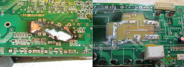
It looks like a TVS was the device in the board. Incidentally, heat does NOT rise in a heatsink- it travels in all directions without concern to orientation. There is a slight effect from heat rising in the air around it, and yes having the cap below it is better than above.
A mate opened a TV repair shop some years ago. I used to drop around Thursday night to help with the difficult bugs, getting paid in non-taxable beer and pizza. It was a lot of fun. One day someone dropped a colour TV around because he had thrown it at his house mate in a fit of rage. I was going to try to fix it the following week. The following Thursday I dropped in and my mate said don't worry - the owner's house mate had murdered the TV set owner. We left the TV for a while in case it was going to used as evidence. In the end I tried to fix it, but I threw it out... the entire main PCB had broken in two and there were too many tracks to try to repair. Some things just cannot be fixed.
Dave mentioned that the sensor inputs have to be terminated with a 2.2k resistor. I don't know if you guys think that it's wrong to post public about such ideas, but it set me thinking how such a sensor could be deactivated.
[...]
Good thinking, but don't quit your day-job.
You would have been detected by one of the sensors before you can even touch one of the cables, because they are all inside the secured area.
Let's say you are able to sneak an articulated arm or similar into the secured area and to the alarm cables.
How would it help to know the values of the resistors? The comparator in the alarm system will react to resistance changes within microseconds or at least milliseconds.
You won't be able to cut the cable and place a resistor between the wires in that time. And you can't pierce the wire and place a resistor in between before cutting: you'd parallel the resistors which is easily detectable by the comparator.

