-
So it looks like the XEN signal is there only for a short time during the transition from the zero signal to the actual signal. This would be before the actual conversion starts. Chances are that both readings in the AZ cycle use the same value of the ZJUMP signal. This way one essentially avoids having an actual zero signal at the ADC. I don't see a big difference between the ranges. It is only a few cases that one actually sees a change in the ZJUMP signal - this seems to happen when just at the edge with the oscillation between the 2 states and thus a more random ZJUMP signal.
This way the ZJUMP part makes some sense: the area around 0 V shows the largest DNL error. Avoiding this range helps with the linearit. Adding the + or - 200 mV to both of the AZ steps gives zero net effect. It looks like a clever technique.
The DCBUF signal looks odd at first. Just keep in mind that this is from a slow LM358 OP-amp. The signal to the ADC will be faster and we see the slew rate of the LM358 to slow down the transition. It is still a bit odd to see the signal to go down and only later up in some cases. So there could be some input current spike from switching. -
The 1 V range seem to have a problem with the settling speed of the amplifier. The DCBuff signal does not get the correct sign in some / many cases. The critical point would be if this also happens near + 20 mV and thus near 0 V getting to the ADC when including the ZJUMP part. If the Zjump part is wrong for the larger voltages, this would not cause an issue as one is still away from 50 % PWM at the ADC.
The settling time for the DCBUF signal in some cases seems to be a bit over 60 µs - this could be extending to the start of the actual conversion, at least for some higher speeds. The DCBUF signal does not have a large effect on the ADC, but there is still some coupling, capacitive and likely mixing a little of the voltage at pins 28/29/30 of U180 to the switch gate voltage. So Ideally DCBUF should be settled before the actual conversion begins.
There could be an issue with the main amplifier settling, the charge spike compensation (can cause overshoot to start with) for the pre-charges switching or just a rather slow LM358 for U170.
It could be interesting to also see the DC_AD signal and maybe the integrator output. -
Next time when I am in there, will make additional measurements.
Would be nice if other 3458A owners could check that behaviour.
As there is limit of 10 attachments, now all screenshots:
100mV -FS / 0V / +FS:
1V -FS / 0V / +FS:
10V -FS / 0V / +FS:
100V -11V / 0V / +11V:
1000V -11V / 0V / +11V:
10V 0V Video:
-
Added additional data for drift after ACAL ALL:
-
I was wondering about the rather low noise level before. With averaging (boxcar integrator like) over many cycles this makes sense.
It looks like the external reference is causing much of the "gain" drift after ACAL. The different reference seem to behave differently. So the settling effect could well come from the external reference and not the meter. There is a chance to have some charge peak when reconnecting the input after ACAL.
With the scope screen shots, the 100 mV range test is a bit odd. The DCBUF signal goes initially up really fast (some 14 V in some 6 µs) normally the LM358 should not have such a high slew rate. The other curves show more a slope limit that would be typical for a LM358 slew rate.
Maybe the LM358 can have a high slew rate when really driven hard (maybe even exceeding it's supply).
The features seen at postive times in the DCBUF curve are likely ringing of the main amplifier. This would be quite strong ringing, all the way to drive the LM358 to the slew rate limit. -
Follow-up on adventure for improving noise.
Replacing +12Vref amp U160 with ADA4522 was disappointing, no significant change.
There is little chance that replacing -12Vref amp U165 with ADA4522 will change something, let alone 5Vref amp U151.
Keep in mind that there is a scaling factor of 1.06 from ADR1000 to LTZ1000.
In comparison to earlier plots, all measurements are linear drift corrected to accomodate for self-discharge in the LiIon cells for 10.6V, that gives the characteristic down slope at the end of the ADEV plots.
-
Thank you for the great documentation of your investigations.
You should have seen a 2-3x reduction in noise in the 100-1000 second range with the ADA4522 chopper opamp.
I use one of my Z10 prototype Voltage Standards when I do the 10V stability test. It has shown 3nV stability over a day when Air pressure and Linear drift affects are removed.
I could only get good Zero stability results by using a simple copper wire short or a gold-plated PCB shorting the input terminals. One shorting plug with gold plated banana jacks had noticeably higher thermal emf and Zero instability.
I have modified 3 units now with good results. There are a few other subtle things I do when modifying the units. I have not quantified these improvements. We are dealing with nanovolt stability over hours.
To minimize noise from thermal EMF, I minimize the A1 shielded enclosure airflow. I close off any openings at the aft end, near the fan, with tape. There are a few holes back there and there are gaps where wiring leaves the plastic shield around the power supply area. I have not noticed a change in compartment temperature by doing this.
On the A3 module I use small cotton balls around the +-12v Opamp and the first comparator. This minimizes any random airflow in this area especially with the DIP to SOIC adapters needed for the newer opamp. On one unit I put cotton balls on the back side of the pcb to also cover the pcb pins and the U180 pins. I pull the cotton balls apart to fluff them up a little.
Do not block the cooling of the EL2018 comparators. They already run hot as it is.
All the pcb mounting screws on A1 and A3 modules need to be tight. Do not break anything but they need to be snug with no missing screws. I expect HP to have a torque spec for these screws somewhere. These screws supply critical grounding for the HP3458A pcbs. Screws made from different metal are not allowed.
With chopper Opamps I add a C0G capacitor between the non-inverting input to chip power ground. I do this on the SOIC adapter pcb. This will minimize current spikes getting into the circuitry.
The parts list for the A3 module specifies 10nF AVX X7R capacitors (AVX PN SA101C…) for the opamp feedback. An X7R capacitor can have 10x the current noise of a good C0G cap. These are C160, C165, C151 and C152. I have removed some of these capacitors by clipping them off the pcb and testing them. Based on leakage current noise they appear to be C0G caps. HP made several different A3 versions over the years. I cannot guarantee what type of capacitor is on your PCB. I replaced the critical 10nf feedback caps with TDK 10nf 100V C0G parts so I know I have the best.
NOTE: If you want to test an X7R capacitor do not unsolder it from the pcb, clip it out. The Heat from unsoldering may change the X7R capacitor characteristics like aging and leakage current.
As I am sure you know, there are several better chopper Opamp than the ADA4522. Below 0.1 Hz the ADA4522 voltage noise density starts to rise like a normal opamp. It still should have 10x less noise than a Bipolar LT1001 opamp at the longer time scales (100-1000 seconds).
The ADA4523, OPA182 and the OPA189 have flat noise spectrums out to 1000 seconds.
On the A3 module I have successfully tested the -
OPA210 Super Beta 2nV Bipolar Opamp, 5x less noise than the LT1001 and lower bias current.
OPA182 5nV chopper (low power OPA189), OPA189 5nV chopper, ADA4523 4nV chopper.
I not have noticed any strange operation over the last year from chopper clock noise interacting with the A3 sampling frequency.
I have also tested the choppers and the Super Beta Opamp in the U110 First comparator location with no noticeable issues.
I changed the U170 opamp (DCBUF) from an LM358 to a OPA2140 for much better bias current stability (1000x), faster operation (faster settling, lower output Z), and better DC specifications.
Good luck!
-
Changing the OP-amps for the ref. amplification may have more effect with slower conversion like 10 PLC. The effective frequency where the noise matters is roughly 1/ (2 * T_integration). For 1 PLC -> 25 Hz the LT1001 is not yet that bad. It is more with 10 PLC that the LT1001 shows 1/f noise that the chopper amplifier can avoid.
I would be careful with the ADA4523: it needs quite some power and has high input current noise. So for a source impedance of some 5 K it would be higher noise than the ADA4522 or OPA189.
AZ amplifier should also have good local decoupling - e.g. an extra capacitor on the SO8 to DIP adapter.
For replacing U170 a OPA2140 is overkill speed wise. The lower power OPA2145 would be well fast enough.
The amplifiers are the ref. amplification contribute a little, but the effect is limited.
The issue is smaller with the ADR1000 based reference, but it could still make sense to have at least a little higher frequency filtering for the reference voltage. Some of the noise in the 100 kHz range can effect the ADC via mixing with the run-up modulation. -
Hello Chuck,
many thanks for details about your 3458A modifications!
I made bad experience with cotton pads on my KEITHLEY 182.
I wanted to thermally isolate the input connector / plug, as well from drafts and stuffed cotton inside.
That led to greatly increased bias currents of the instrument, maybe due to humidity absorption.
It was completely un-usable afterwards for zero alignments in bridge applications, like with the FLUKE 720A or FLUKE 752A.
So I had to remove the cotton again.
Air drafts in the 3458A and in other instruments (34465A / 470A, 34970A) are really a severe design error.
I isolated the LM 399 / LTZ1000A reference inside my 34465A with a small plastic box around the whole reference circuit area, which clearly reduced noise from air draft, which directly blows from the fan in direction of this circuit.
Maybe I overlooked that detail of your description, but why haven't you as well shielded the A9 circuit area from air drafts?
Another aspect concerning the ADR1000 reference possible recovering drift:
How do your modified 3458As behave, when you switch them off your days, or weeks?
How long takes their ADR1000s to recover?
Is it instantly (like with the LTZ1000A reference board), or do you see several days or up to 2 weeks of enhanced drift, on the order of several ppm?
Thank you!
Frank -
Thank you Chuck for the deep insights

Would be nice if you could share some pictures of your mods.
You are right, ADA4522 was a consciously decision for my A9 ADR1000 (low Iq - low heat, low enough noise).
For your QVR with around half the noise, ADA4522 would spoil noise significantly (~50%), for my A9 it is <10%.
Did you compare noise U110 1st integrator stage before/after swap?Changing the OP-amps for the ref. amplification may have more effect with slower conversion like 10 PLC. The effective frequency where the noise matters is roughly 1/ (2 * T_integration). For 1 PLC -> 25 Hz the LT1001 is not yet that bad. It is more with 10 PLC that the LT1001 shows 1/f noise that the chopper amplifier can avoid.
10NPLC no relevant change either:
Be careful on interpreting the 10.6V ADEV charts, as the setup was not the best - a Z10 would be handy...
The U160 measurements should be reasonable, but far from insignificant for longer integration times - NSD plot is mostly unaffected.
It might be due to just checking positive range, the run-up should mostly use the -12ref, which is still stock LT1001 right now.
On the other hand I would expect lower noise at 0V input, as pos & neg ref should be used nearly equally for the run-up.
Maybe the ADC core is just limiting noise now? How to estimate the noise contributions of the components from integrator/slope amp/comparator?
-
The possibly changes to the 3458 ADC are somewhat limited, as the core U180 and logic is fixed.
So the possible improvements are really limited. I did some math on the noise source for the 1 PLC AZ case. There are a few parts with estimated paramters, but the rough size should be about right, maybe a bit more jitter.
Form this the largest noise source with there contribution (need to add up as squares - so the large ine really matter and the small one less)
1) the 50K+40 K resistors at the integrator: 306 nV
2) 150 kHz band ref. noise ~190 nV , unclear how noisy the ref. actually is at that high frequncy, The ADR1000 can already help here
3) U110 (integrator) 184 nV
4) jitter in U180 and U131 ~ 150 nV assumes 1 ps RMS jitter
5) U165 and the 10 K resistors there 144 nV
6) reset noise from switch capacitance ~ 120 nV assume 10 pF
7) front end protection 90 nV
8 ) quantization noise 59 nV
Even when measuring -11 V and thus mainly using the positive reference the zero reading in the AZ cycle still has both signs about half the time.
When changing U110 one may also have to adjust R112/ R114 for a likely higher BW of the replacement.
To a large part I would consider the ADC noise to be at it's limits. -
Attached are some photos from my mods. I got a little carried away with the cotton in the one picture. I usually have about half of that.
My 1st gen A9 QVR has a combination of 3D printer cover, cotton and Kapton to minimize air drafts. The 4 ADR1000s have 50 ohm current setting resistors and a 12.5k temperature setting resistor (66 deg C).
This one has stopped drifting after 18 months. The other two QVRs are still drifting several ppm / year. I recalibrate them to my Wavetek 4911s or Z10s when needed.
My machines run 24/7 doing various testing so I have not seen a voltage shift with extended power off. I may be able to test that this month.
The new Opamps for the A3 mod are on SMT adapter pcbs plugged into gold plated machined pin sockets.
I'm building a dual ADR1000 A9 board now from TiN. This design does not require any modifications to the A1 PCB.
With a high current QVR and choppers in A3 I may have reached a flicker noise floor for the A3 ADC.
Better 20MHz oscillators did not help.
The performance limit may be Excess Noise in the U180 resistors. Some of the main resistors have 7V across them. An excess noise index of -50dB (very very good) would yield the 40nV noise floor that I am seeing.
Next areas -
1. Reduce the noise of the Internal +-10V reference with a better Opamp (U400). I believe these voltages are used as internal transfer standards during ACAL and for resistance measurements. Replacing the LT1013 with an OPA2182 chopper will reduce the internal reference voltage noise 4-5x.
2. A small heater to hold U180 at a constant temperature. U180 should be able to be controller to 0.01 deg C. See photo. A small heater pcb is attached to a chunk of aluminum. U180 temperature sensing is from a thermistor in the hole in the middle of the aluminum heat spreader.
Concept -
A very small processor would control the heater. The heater is sized to provide a maximum of 10 deg C temperature rise. At startup the heater goes to 50% power for a 5 deg C temp rise of U180. After 2-3 hours the processor notes the temperature and starts controlling to that. Then the temperature of U180 will be held steady as ambient changes +-5 deg C. If the heater control reaches an edge, change the setpoint 2C up or down as needed and keep controlling.
3. Take a very low noise 7.14V from the Z10 Voltage standard (2-3nV noise level) and use that in place of the A9 module. Find the ultimate limits of the A3 ADC in the HP3458A.
The white noise limit of the A3 is pretty much fixed by design but I think there may be room to improve the flicker noise floor and the temperature stability.
Should be fun.
-
Not sure about the DIP to SMD adaptors towering up from the Pcb like that, and I had the same thoughts when I decided to do something similar on my 3245A.
What I did was create a custom 8-pin DIP to SMD board that's single sided and had castellated holes so that they could be soldered directly onto the main board.
No need for pins/legs, the castellated holes mean you can solder in place over the original 8-pin footprint.
UPDATE: If you get them made, then choose 1.0mm thick PCB as I found that preferable to the normal 1.6mm FR4.
Gerbers attached if you want them plus some pics.
Ian.
-
Comparison of noise of ADC (Jumper P100 near A9 set to GND/+7)
AZ on:
1NPLC has significant lower noise than 10NPLC (n x 10NPLC), it needs 3-4 times longer integration times to reach the same noise level (ADev plot).
For 1NPLC the noise with external short, internal short & Ref (ADC only) is essentially the same, at 10NPLC the Ref noise is higher compared to the shorts.
The noise for LTZ#3 (longer integration times) and 10.6V (shorter integration times) is mostly limited by instrument - the noises can not be compared directly (7.1V vs. 10.6V).
-
Air drafts in the 3458A and in other instruments (34465A / 470A, 34970A) are really a severe design error.
Have you identified areas in the 3458A that are susceptible to air drafts?
I isolated the LM 399 / LTZ1000A reference inside my 34465A with a small plastic box around the whole reference circuit area, which clearly reduced noise from air draft, which directly blows from the fan in direction of this circuit.
I note with my 3458A that there seems to be a hot spot around the input terminals area when scanning the case exterior with a thermal camera. The hot spots are more severe around the openings for the terminations and guard switch buttons indicating that there is quite a bit of heat escaping from behind this area of the front panel.
The thermal camera also seems to show a slight 0.5℃ difference between the temperatures and the HI and LO terminals but I will have to put some thermocouples on those terminals to get a more accurate determination. -
Air drafts in the 3458A and in other instruments (34465A / 470A, 34970A) are really a severe design error.
Have you identified areas in the 3458A that are susceptible to air drafts?
I isolated the LM 399 / LTZ1000A reference inside my 34465A with a small plastic box around the whole reference circuit area, which clearly reduced noise from air draft, which directly blows from the fan in direction of this circuit.
I note with my 3458A that there seems to be a hot spot around the input terminals area when scanning the case exterior with a thermal camera. The hot spots are more severe around the openings for the terminations and guard switch buttons indicating that there is quite a bit of heat escaping from behind this area of the front panel.
The thermal camera also seems to show a slight 0.5℃ difference between the temperatures and the HI and LO terminals but I will have to put some thermocouples on those terminals to get a more accurate determination.
Well, the 3458A works much more stable if you have a constant room temperature. Varying temperature makes precise / stable measurements and transfers impossible.
This fact alone demonstrates, that it is susceptible to such effects.
Directly I observed this behaviour with my KS34465A, where you can clearly see that the fan blows over the reference area and applying a shield (with the LM399 mounted), explicitly reduces the usual reading noise. Same effect on the 34465A but with the LTZ1000A board assembled.
As others already wrote, the 3458A like all other DMM is slightly sensitive to air draft on its input jacks. I simply close the door of my basement lab and I don't move when I'm doing the measurements, otherwise I directly see an increase in the StD value.
I think, the main effect is creation of e.m.f., but to a much lesser degree any heating from its interior.
If you watch some videos from TiN, he always puts a shielding box around the input and output jacks of his calibrators and his 3458As.
When you look on the analogue board of the 3458A from above , you'll see some holes in the shield, where air from the fan might enter, and as well might blow partly over the reference.
I didn't test what happens if I would shut off this air flow, because the continuos temperature increase will definitely shift the reference value by its T.C., replacing a noise instability by a drift instability. Latter might be the higher contribution.
Maybe Chuck could give a more detailed description (with pictures), how he has isloated his 3458A from internal air drafts on the analogue board.
Again, I avoid cotton pads as these definitely create leakage currents.
Frank
-
I have used Cotton to baffle the airflow. I have also used Dacron to slow the air movement. Dacron (Terylene) is a polyester batting used in upholstery and clothing.
I will see about getting some better pictures the next time the cover is off. -
Comparison of noise with turn over (-12V ref amp U165 is still stock LT1001):
Quite some noise difference between positive and negative input voltage to the higher frequencies, at lower frequencies the difference vanishes.
-
Drift of A9 ADR1000 over around 2 months:
A9 ADR1000 drift is very close to drift of LTZ#3, couple of short downtimes and couple of hours upside down operation have negligible effect on this ADR1000.
Initial drift has settled to -2.6ppm in less than a month, drift since 24th of Feb should be <1ppm/a.
The residual TC of 3458A in 10V range is around -0.06ppm/K (combined TC of A9, LTZ#3 (<+0.01ppm/K) & signal path outside of ACAL coverage).
Premises:
- linear interpolation of temperatures from hourly ACAL (CAL175)
- ACAL noise correction of readings (around ±0.1ppm) - no further corrections applied
- datapoints are rolling 5min means of readings (100NPLC, 4.2s)
- filtered temperature range 31.9 - 32.8°C (best coverage of readings)
- Feb: A9 ADR1000
- Mar: A9 ADR1000 & U160 ADA4522 (+12V ref amp)
- Apr: A9 ADR1000 & U160/U165 ADA4522 (±12V ref amps)
- LTZ#3 drift is around -0.6ppm/year, 2 month: around -0.1ppm
-
Update of noise comparison between mods.
4W Short:
Only small improvement with upgrade to A9 ADR1000, otherwise no significant difference for upgrading the Ref amps U160&U165.
ADC short (Jumper P100 near A9 set to GND) shows only little difference on long integration times / low frequencies - this means there is insignificant contribution from AFE (23nV flat, rising to 130nV @1mHz - see last figure).
The red line is a bit off on long integration times / low frequencies, 10NPLC is similar to the others, so this should be just a fluke (no abnormalities in the timeseries visible, only a small dent at the beginning).
FS (10.6V 3xLiIon):
Similar picture as for short, only small improvement with upgrade to A9 ADR1000.
ADC FS (Jumper P100 near A9 open & jumper from U160 out to ADC input DC_AD) shows the noisefloor of the ADC at 12V input and is similar to ADC short (AZ to +12ref) - it is mostly gaussian noise ~130nV/Hz^0.5 (as claimed in HP journal p.14).
Noise of +12ref should be ~25nV flat / ~80nV @0.1Hz, -12ref ~35nV flat / ~85nV @0.1Hz (ADR1000 + Ref amp noise).
This is insignificant contribution to ADC noise, which is in accordance with the measurements.
Noise of AFE (100mV range):
-
Some updates on modding my A3 for lower noise.
The next mod was replacing +5ref amp U151 with ADA4522 and fet modulation U170 with OPA2206.
Unfortunately this did not work, the noise went up dramatically.
Simulation showed that with ADA4522 and the additional BJT Q151 at the output it is at the edge of stability - even with original LT1001 not that good.
As C151 & C152 had to be changed anyway, it was a good opportunity to test if it makes any difference with more filtering on all ref amps.
C160, C165, C152 were replaced with 10µF film and an additional capacitor between +5ref and +5sum added, C151 replaced with 150nF.
The last mod was replacing the first integrator stage U110 with OPA205.
4W Short:
FS (10.6V 3xLiIon):
For the last mod there is currently no data available.
Overall the improvements are only for short time intervals for this rather noisy A3, but the TC did improve - more on that in a later post.
The improvements are likely from more filtering of noisy -12ref 2x10k divider.
The comparison of positive and negative FS showed a significant difference in noise between 0.1 to 20Hz, which was confirmed by quick bodge with external 2x10k divider.
Noise bump from -12ref divider comparison to other units:
-
U170 (input buffer and driver for input switch supply) may see capacitive loading. If stability there is an issue, the OPA2202 could be an option: it is more tolerant to capacitive load (could even add some 5 or 10 nF) for the switch supply.
The OPA202 would also be a candidate for U151. The effect from U151 is still expected to be small as this part should only be active during run_down. C152 is slowing down U151 and it should not be a good idea to increase this capacitor.
When changing U110 to a faster amplifier one may have to increase R112 to get the same response. Othewise one may get some extra INL from additional response to some lower frequency parts (~ 2 kHz) close to some critical voltages (e.g. 7.5 V).
The change in the OP-amp would definitely be a point that could give a little improvement. The improvement could be more significant at 10 PLC than 1 PLC as the new OP-amp may well have less 1/f noise.
C160 / C165 are not just filtering the little noise from the 10 K resistors. They also filter the noise from the LTZ1000 to some degree. The ADC does react to some of the higher frequence reference noise. Here the original 10 nF capacitors should alread supress most, but maybe not all. A possible point worth testing could be filtering of the reference before U160, at least for the rather fast part.
-
Hello MiDi,
I have forgotten about your great blog.. so may I again give the hint, which I already have published somewhere else, that the original LTZ1000/ADR1000 schematic for A9 gives a noteworthy EMC disturbance/noise inside the HP3458A?
Root cause is the extreme sensitivity of the LTZ circuit, if any RF irradiation is present. There are several RF sources inside the inner GUARD shield, so the HP3458A shows strange "bumps" up to 0.1ppm, when making 24h stability measurements on 7.15V references. Using a differential comparison method between two such references simply gives a nearly flat line, fluctuations below 0.05ppm pp.
By adding those 4 EMC capacitors, including the RC low pass, copyright Andreas, these bumps completely vanish, and the 3458A can equivalently be used with low noise, like the differential method. One of these 4 caps is already assembled on the A9 board, but should be replaced by a film capacitor.
Advantage is the additional scaling function, i.e. you can "differentially" compare 10V and 7.15V, but disadvantageous is the residual, too high T.C. of about 0.5ppm/°C, i.e. absolutely stable room temperature required.
This measure also improved the usual StD value for a NPLC 100 reading from typ. 200nV to 150nV, if I remember correctly. Or to explain it in a better manner, I achieve such 150nV StD measurements much more often when I'm doing my regular transfer / comparison measurements between my different references.
Recently, I have doubled the zener current for the LTZ1000, which gives slightly lower noise, and put a plastic cap over the A9 board, like in my 34465A. There was no noteworthy improvement to latter measure.
Have you ever implemented some/all of the hints by ChuckB, and were you able to confirm his hints?
As said, the ADR1000 is not usable in a bench DMM, as it shows this big hysteresis even after only 1, 2 days off. Either AD is willing to change its die attach to the ones of the LTZ1000, or inside the HP3458A you'd need to add an addtional small transformer, attached directly to the mains plug, an additional small 12V power supply, and battery backup. I guess, there's enough space left near the big transformer.
Have you recently heard anything from Illya, ChuckB or others in the U.S., who also have investigated on this topic?
Happy 4th Advent, Frank
-
U170 (input buffer and driver for input switch supply) may see capacitive loading. If stability there is an issue, the OPA2202 could be an option: it is more tolerant to capacitive load (could even add some 5 or 10 nF) for the switch supply.
The OPA202 would also be a candidate for U151. The effect from U151 is still expected to be small as this part should only be active during run_down. C152 is slowing down U151 and it should not be a good idea to increase this capacitor.
When changing U110 to a faster amplifier one may have to increase R112 to get the same response. Othewise one may get some extra INL from additional response to some lower frequency parts (~ 2 kHz) close to some critical voltages (e.g. 7.5 V).
The change in the OP-amp would definitely be a point that could give a little improvement. The improvement could be more significant at 10 PLC than 1 PLC as the new OP-amp may well have less 1/f noise.
C160 / C165 are not just filtering the little noise from the 10 K resistors. They also filter the noise from the LTZ1000 to some degree. The ADC does react to some of the higher frequence reference noise. Here the original 10 nF capacitors should alread supress most, but maybe not all. A possible point worth testing could be filtering of the reference before U160, at least for the rather fast part.
At least in my unit U170 has a problem that the OPA2206 should solve:
The input exceeds the supply rails by up to 3V during input switching in A1 and LM358 responds with a long recovery time - see: https://www.eevblog.com/forum/metrology/3458a-worklog/msg5870289/#msg5870289 & https://www.eevblog.com/forum/metrology/3458a-worklog/msg5871583/#msg5871583
Have not recognized any problems with OPA2206 so far.
Increasing C152 of +5ref amp is counterintuitive for me too, but simulation shows good response and stability for the values used and it works good in circuit.
If there is a problem with OPA205 for U110 w/o increasing R112, why would that only effect INL (at critical voltage) and not noise?
In my very limited understanding, R112 & R114 reduces the AC gain to maintain stability of the integrator.
FYI: the CLIP has wrong value for R112 in schematic, it is 5.62k (not 33.2k, CLIP BOM is correct and verified against all known A3 revisions), R114 is 100R.
Schematic: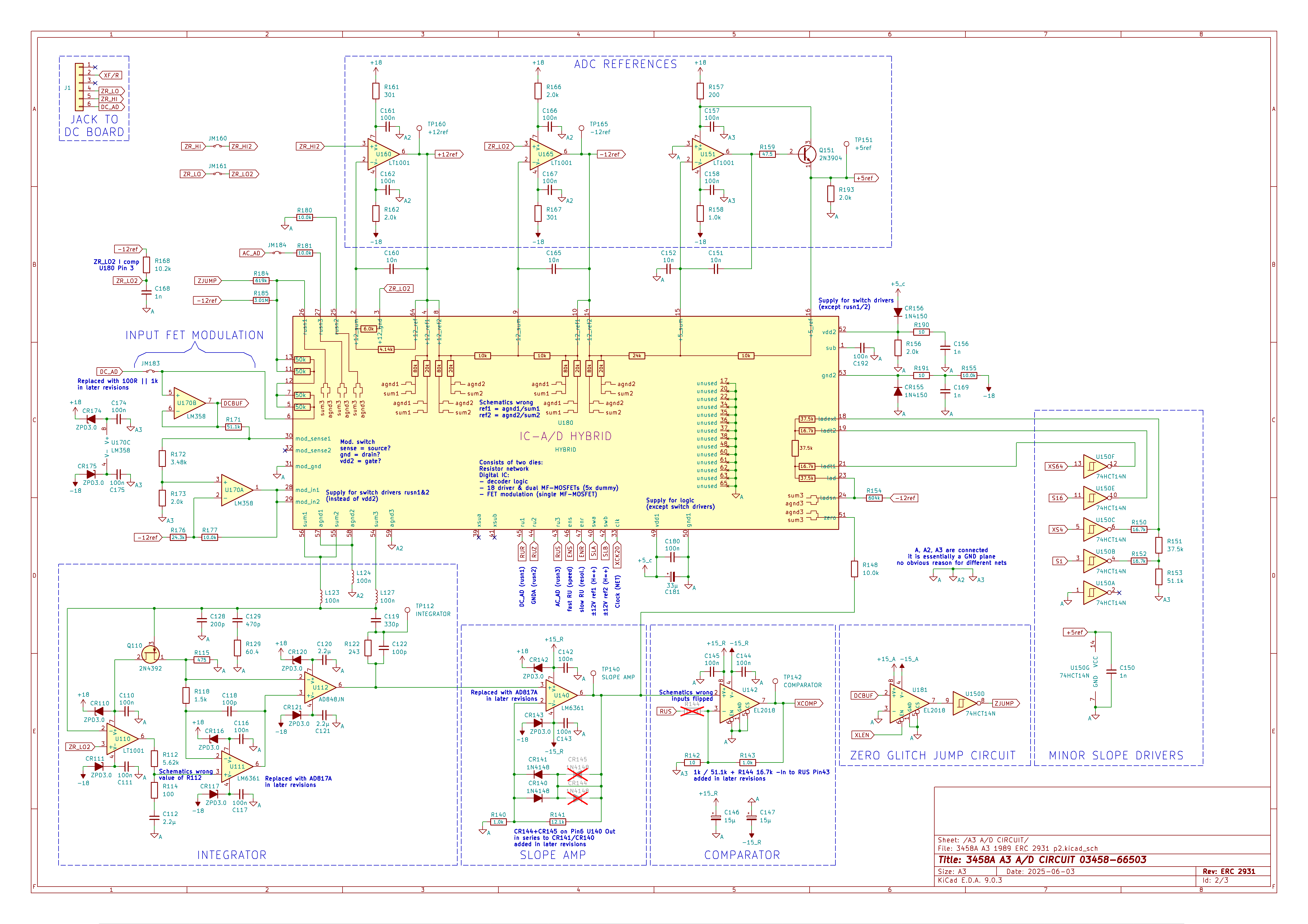
Simulation of integrator:
LT1001:
OPA205:Hello MiDi,
I have forgotten about your great blog.. so may I again give the hint, which I already have published somewhere else, that the original LTZ1000/ADR1000 schematic for A9 gives a noteworthy EMC disturbance/noise inside the HP3458A?
Root cause is the extreme sensitivity of the LTZ circuit, if any RF irradiation is present. There are several RF sources inside the inner GUARD shield, so the HP3458A shows strange "bumps" up to 0.1ppm, when making 24h stability measurements on 7.15V references. Using a differential comparison method between two such references simply gives a nearly flat line, fluctuations below 0.05ppm pp.
By adding those 4 EMC capacitors, including the RC low pass, copyright Andreas, these bumps completely vanish, and the 3458A can equivalently be used with low noise, like the differential method. One of these 4 caps is already assembled on the A9 board, but should be replaced by a film capacitor.
Advantage is the additional scaling function, i.e. you can "differentially" compare 10V and 7.15V, but disadvantageous is the residual, too high T.C. of about 0.5ppm/°C, i.e. absolutely stable room temperature required.
This measure also improved the usual StD value for a NPLC 100 reading from typ. 200nV to 150nV, if I remember correctly. Or to explain it in a better manner, I achieve such 150nV StD measurements much more often when I'm doing my regular transfer / comparison measurements between my different references.
Recently, I have doubled the zener current for the LTZ1000, which gives slightly lower noise, and put a plastic cap over the A9 board, like in my 34465A. There was no noteworthy improvement to latter measure.
Have you ever implemented some/all of the hints by ChuckB, and were you able to confirm his hints?
As said, the ADR1000 is not usable in a bench DMM, as it shows this big hysteresis even after only 1, 2 days off. Either AD is willing to change its die attach to the ones of the LTZ1000, or inside the HP3458A you'd need to add an addtional small transformer, attached directly to the mains plug, an additional small 12V power supply, and battery backup. I guess, there's enough space left near the big transformer.
Have you recently heard anything from Illya, ChuckB or others in the U.S., who also have investigated on this topic?
Happy 4th Advent, Frank
We talked here: https://www.eevblog.com/forum/metrology/ultra-precision-reference-ltz1000/msg6005203/#msg6005203
You can compare it to my A9 ADR1000 design, which incorporates most of that: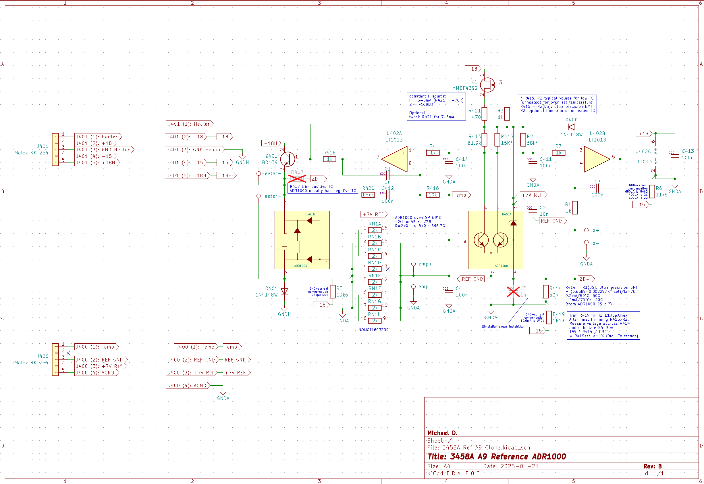
Post: https://www.eevblog.com/forum/metrology/3458a-worklog/msg5790221/#msg5790221
Project: https://github.com/EleDes/3458A_A9_REF_PCB_KICAD
-
With the higher voltage spike beyond the supply range the OPA2206 makes sense for U170. Otherwise it is some overkill.
In the integrator the 3 OP-amps are responsible (set the accuracy and noise) for different frequency ranges. U110 is responsible for the frequencies up to GBW * R114/R112. With the LT1001 this would be up to some 5 kHz. U111 should be active to about 1 MHz (R118*C118) and U112 for the higher frequencies. A faster amplifier for U110 would extend the range where U110 determines the noise and as the AD817 / LM6361 are relatively noisy, the OPA205 would reduce the noise in this frequency range. However this frequency range has rather little effect as the relevant frequencies for the run-up part should be like the input response (SINC response with a relatively low limit set by the integration time).
For the rundown part the frequency band from some 25 Hz - 4 MHz (set by the BW of the slope amplifier) is relevant and here the part from 5-50 kHz is only a small fraction. The run-down noise is anyway relatively small for 1 PLC and more.
Even with the faster OPA205 the cross over the U111 is still enogh separated from the next step and there should be thus no stability issue. If the change does effect the INL is a bit tricky to say - likely not, as U112 and U111 already keep the voltage low that U110 sees from reference switching. My fear was from looking in the time domain and with an additional slower time constant the settling after reference switching could have a slower. Likely this comonent is no excited much and the time constant is still long compared to the modulation.