-
NEW PDVS2mini DC Voltage Reference from Ian Johnston - Reviewed.
Posted by TheDefpom on 27 Aug, 2019 22:07 -
Hi All,
I thought I would pop this here, I just published a review of a new piece of equipment from Ian Johnston, the PDVS2mini, which is a 0-10V DC voltage reference.
No doubt you will spot things I am doing wrong, I'm not a metrology guy after all, but hopefully the video demonstrates the capabilities of the unit.
-
Hi all,
Working on a couple of software bugs at the moment, mostly down to the math.h library which isn't great on these small AVR's (it can't add or subtract properly!). So, having to write (C++) around the issue which is a pain.
Scott's low end non-linearity problem I don't experience on my own PDSV2mini's here.......so some detective work is required.
Prototyping Happy days!
Ian. -
So, the Integral Non-Linearity is higher than the PSVS2, but because resolution is also higher it is compensated for in software?
-
Scott, your meter also has INL which is not zero. You could use your F343 and make differential measurements to get more into that.
-branadic- -
So, the Integral Non-Linearity is higher than the PSVS2, but because resolution is also higher it is compensated for in software?
PDVS2 (18-bit DAC9881) INL = +/-2 LSB typical, +/- 3 LSB max.
PDVS2mini (20-bit MAX5719A) INL = +/- 1 LSB typical, +/- 20 LSB max.
The +/- 20 LSB is scary (when volt-nutting) so there is 11 y=mx+c calib setpoints between 0 and 10Vdc output (1Vdc apart).......to compensate/help minimize any deviation.
An alternative solution would have been to add in an ADC (low INL) and monitor the DAC output and compensate accordingly, but that just pushes the BOM/complexity up..........
Ian. -
Scott's low end non-linearity problem I don't experience on my own PDSV2mini's here.......so some detective work is required.
Assuming the PDSV2mini does no range switch, this simply shows the DNL.
The DS states a DNL of +-1LSB@25°C -> +-10uV@10V FS (This means that this DAC even may not be monotonic).
And it is unlikely that this is only in the low end, the Fluke meter has not enough resolution to show this accurate in 1V/10V range - as Scott already stated.
Ian, are you sure that yours have better DNL? -
I have 2 others sitting here from the same batch and an older one......and on my 3458A no real linearity problems (exception: see below) including at the low end.
However, I had found an issue with the firmware which generated a 1 or 2bit random inaccuracy. It's a well known math.h library problem (it can't subtract/divide properly and shows up as a rounding error!). It's fixed now and makes a nice difference.
This weekend I'll check Scott's video properly and look into the low end issue......but I am beginning to think it's just DNL as we are right down at 1bit step changes......which are magnified in Scott's mV mode on his DMM. My testing has been done on the same 3458A mode across the full range and shows no difference between high or low.
Maybe I will try adding a range selection like I did on the PDVS2, an extremely low RDSon Fet and a low tempco resistor or two. This DAC doesnt have the same Vref range unfortunately, but there are other ways. Hmmmm!
Ian. -
Ian did a firmware update to 1.01 which I applied to my prototype unit (Ian corrected a problem the math library, as mentioned above), the unit steps by 10uV without missing a beat now, I barely even noticed the original issue anyway but now it is fixed.
-
Ian did a firmware update to 1.01 which I applied to my prototype unit (Ian corrected a problem the math library, as mentioned above), the unit steps by 10uV without missing a beat now, I barely even noticed the original issue anyway but now it is fixed.
Yep, V1.01 is definitely a winner, and subject to some on-going testing being completed I should be going into production in the coming couple weeks.
Maths error:-
On 8-bit Atmel AVR controllers the float type is 32-bits which makes the limit 6 or 7 digits......close to the bone and causes rounding errors when working at 5dp's.
So, rather than rely on the maths library doing any rounding I have taken control of it just before converting and sending to the DAC......thus forcing it the way I want it.
Anyone interested in purchasing please use the NOTIFY ME link and as soon as I have stock you'll get an email.
https://www.ianjohnston.com/index.php/onlineshop/handheld-precision-digital-voltage-source-2-mini-detail
Ian. -
Can't wait to get one

You should consider an STM32, not only will it use less power than the AVR, but better software and libraries too -
You should consider an STM32, not only will it use less power than the AVR, but better software and libraries too
Something for the future maybe........but what puts me off slightly is the lack of EEprom, albeit they do have EEprom emulation in flash via paged memory or something like that........well, thats as much as I know about STM32 anyways.
Ian. -
STM32 have both eeprom (STM32L010F4 for example) and non volatile flash, depending on the model, which will allow you to store calibration constants and so on, but why do you need eeprom specifically? the API for reading and writing to the flash is quite fine, maybe I'm missing somethingYou should consider an STM32, not only will it use less power than the AVR, but better software and libraries too
Something for the future maybe........but what puts me off slightly is the lack of EEprom, albeit they do have EEprom emulation in flash via paged memory or something like that........well, thats as much as I know about STM32 anyways.
Ian. -
I don't like STM, their marketing here in TW failed hard when I tried to get some support to consider using STM32 on a project.

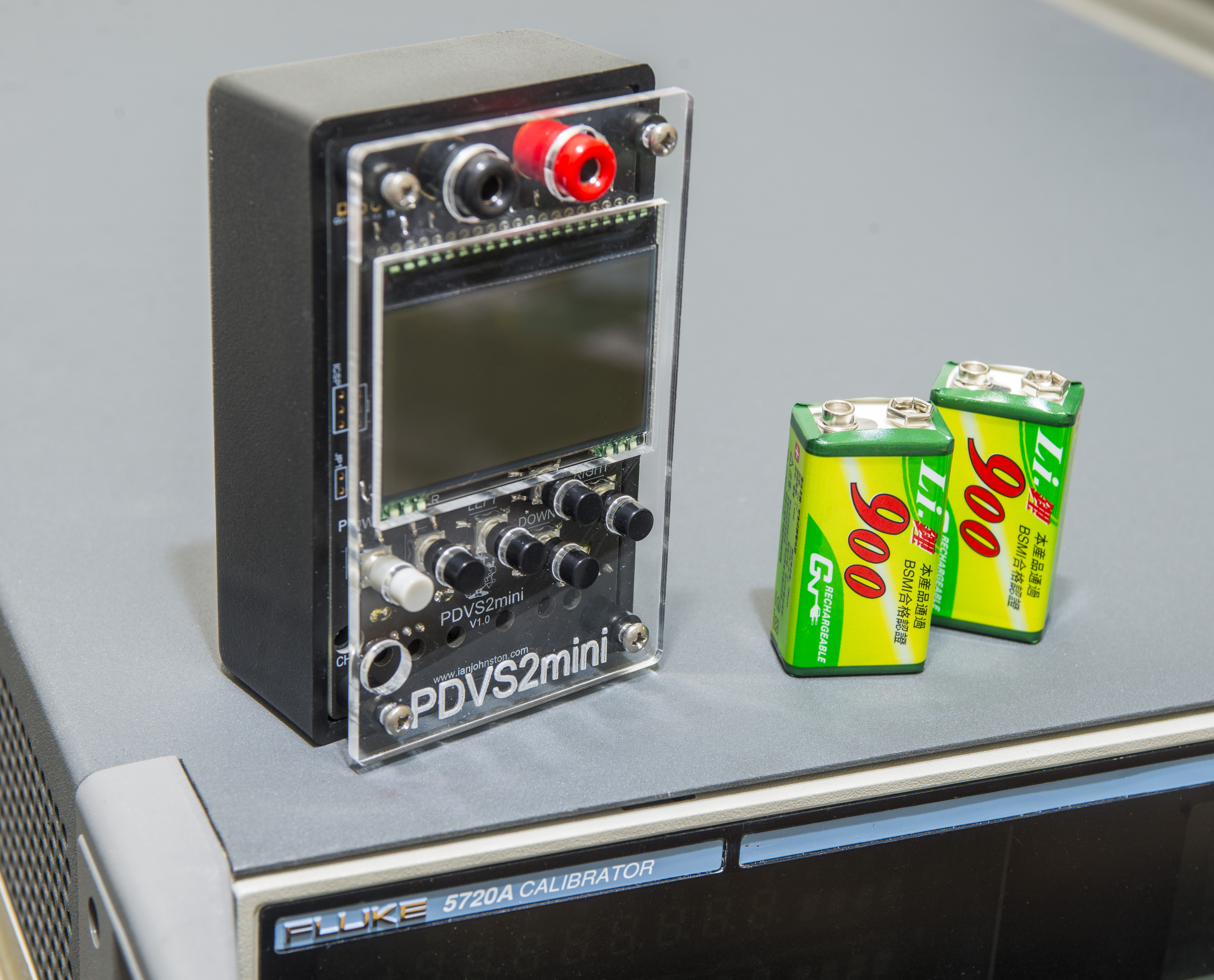
Now let's get back on topic. I got this little cute PDVS2mini in thermal box, runningfor lifefirst quick and dirty tempco test.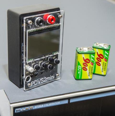

I'm sure somebody will dig a photo with $70K vs $300 DC source .
.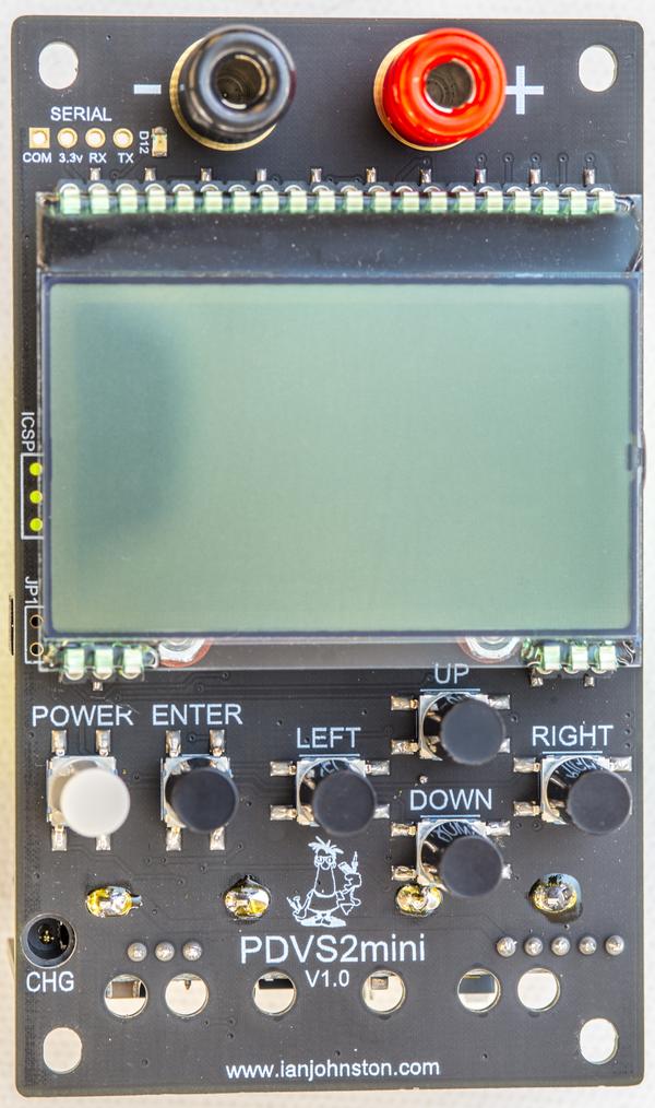
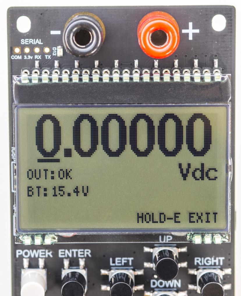
Design assembly is nice and tidy, with all critical stuff well cared. Graphical LCD is not backlit, just COG panel. It has decent contrast and main output voltage have nice large digits. The menu system is little unusual but not hard to figure out without any RTFM. There is a help string on the bottom strings to show keypad actions.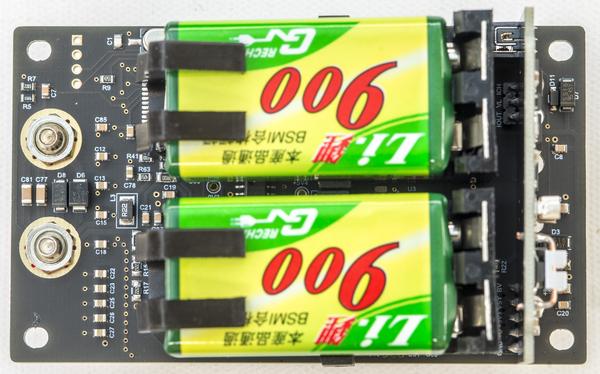
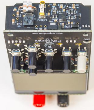
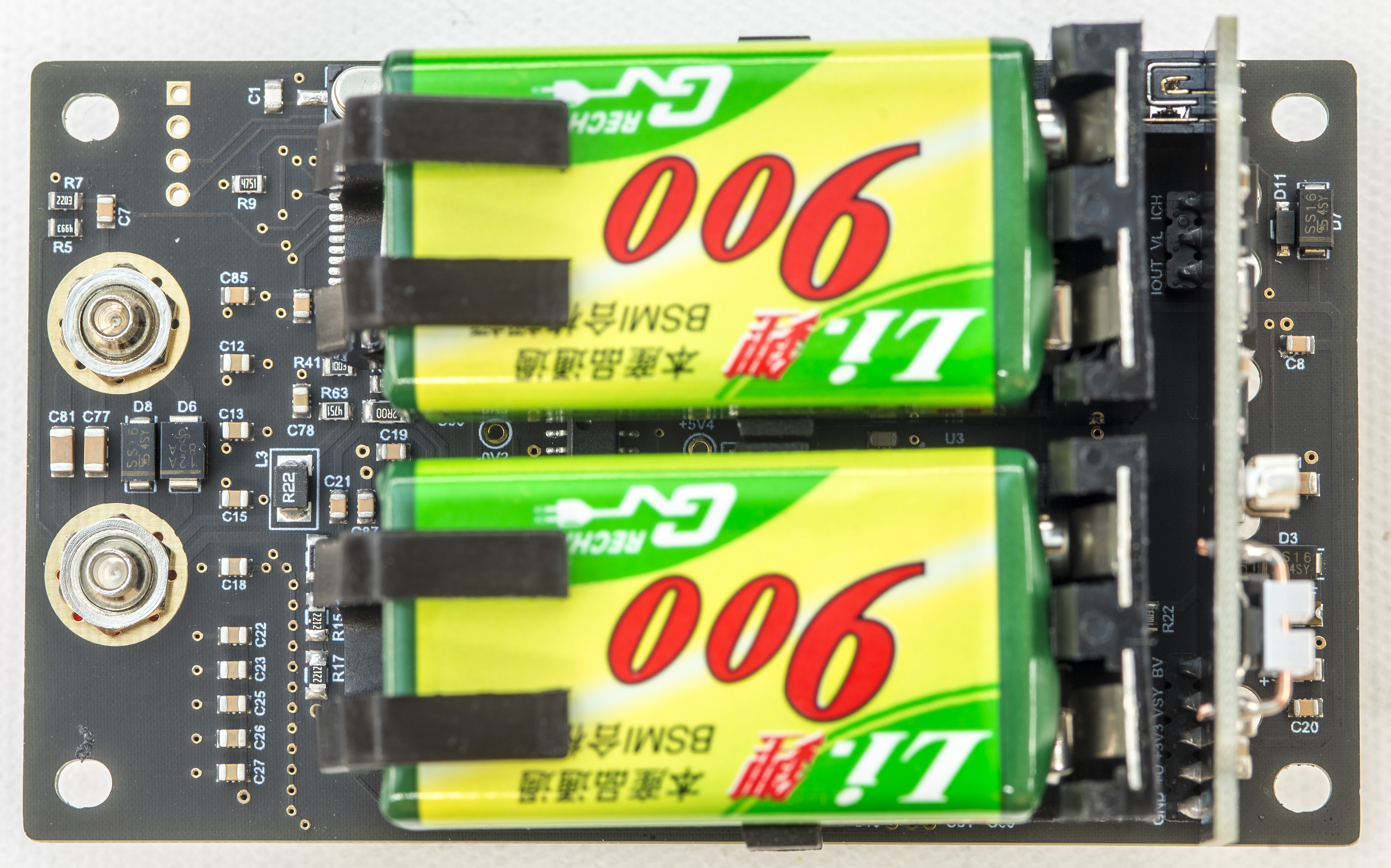
Access to battery requires removal of 4 screws, and also provide a way to see some internal construction.
There is no separate battery compartment or protection over electronic parts, due to low-cost targeting reason, which is understandable.
PDVS2mini designed to use two 9V batteries in series, with integrated charger. Unit needs to be powered on to allow charging from external DC jack.
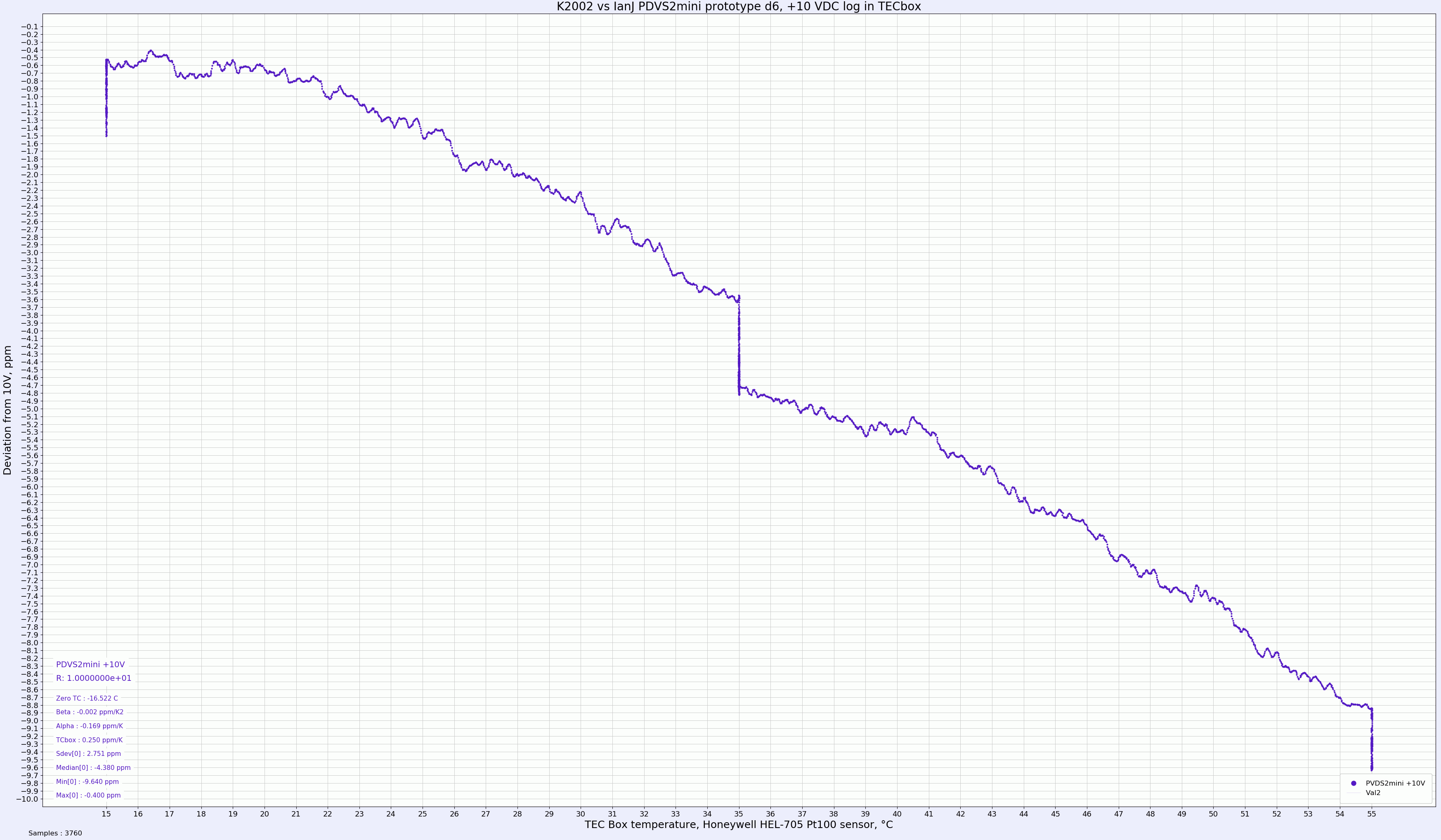
I'm working on detailed review/testing, but it will take some time, so here are just some initial dirty results using my secondary equipment (K2002 and Arroyo TECpak controlled box).
PDVS2mini is powered by batteries, placed in DIY chamber. Raspberry Pi controls Keithley 2002 as a digitizer, and TECpak 585 for precision temperature control. 40W noname TEC used as cooler/heater, with water-cooling loop dissipating heat into room elsewhere. The sensor in the box is Honeywell HEL-705-1 100 Ohm platinum RTD. This thermal box setup may not look like much, but its able to maintain any programmed temperature from -5 °C to +65 °C with better than 0.008 °C stability over hours.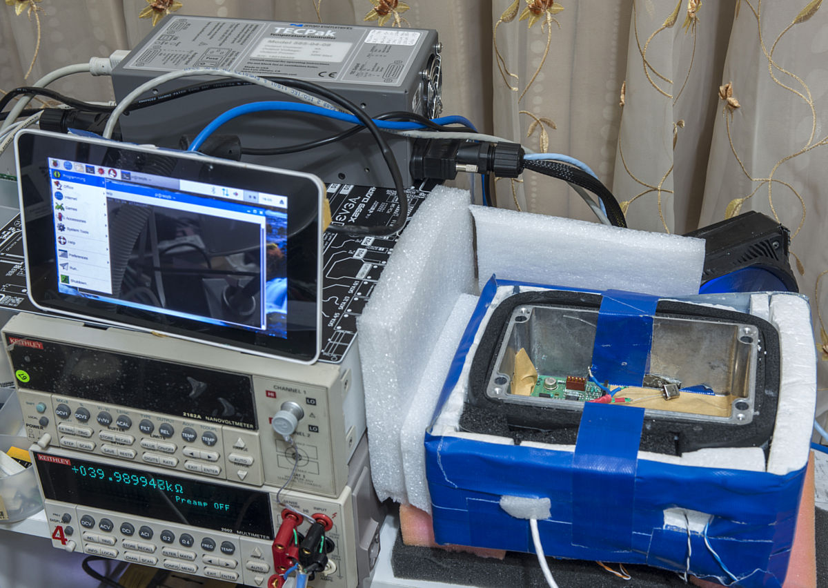
Now to the first test results. The first graph is a plot of +10V output from PDVS, with temperature change from +15.00 °C to +55 °C in a slow and controlled manner. There is soaking time at +35°C for 2 hours, and also at peak max temperature, to get an idea of settling and hysteresis behavior. The horizontal axis is time duration, vertical axis is deviation from initial point at +15 °C, which happened to be +9.999994 VDC +/-2ppm.
For illustrative purposes, chart have additional plots of -0.1 ppm/K and -0.2 ppm/K thresholds based on temperature change (using box method) and TEC current readout from Arroyo TECpak 585. Ramp up time for temperature is +0.08333 °C per minute. Measured deviation is -4.0 ppm for +15.0°C to +35°C ramp, and another -5.3 ppm for +35°C to +55°C ramp. Following the TC Box method we can estimate temperature stability at max -0.23 ppm/K which is impressive for $300 USD DAC box!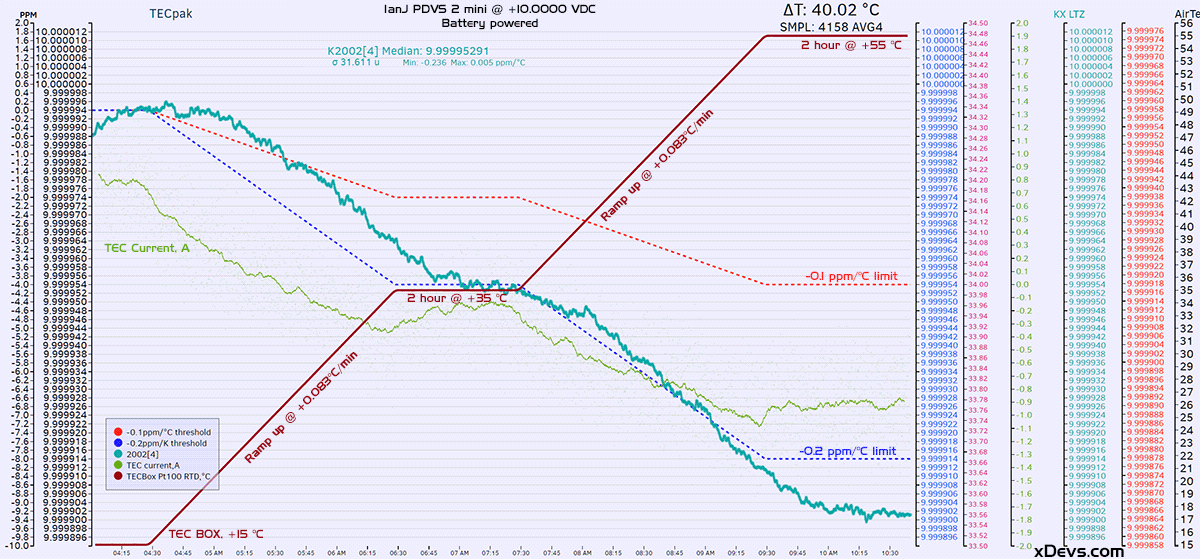
Now same data, but in voltage/temperature scale representation.Hysteresis on fixed temperature points is around ~2ppm but that will need additional verification with proper setupUnit may need additional time, longer than 30min to get temperature soaked to reach equilibrium. This particular temperature chamber does not use forced airflow, and from datalog looks like it need ~30 minutes to equalize temperature change.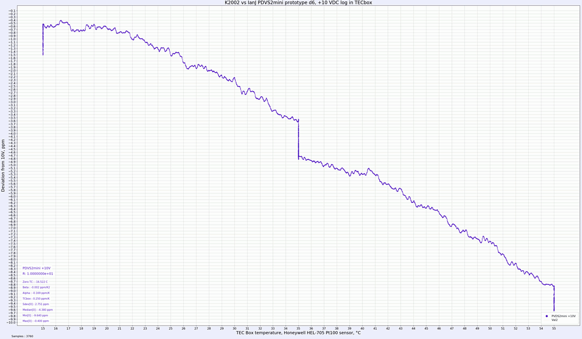
Stay tuned for more
One part I'm not very happy about is banana-only output connectors. Once initial testing and calibration verification test is done, these will be for sure changed to some proper low-thermal EMF hardware .
.
If somebody wants particular test setup/conditions - feel free to give feedback. -
And battery died after 12.5 hours.
-
When you consider that most people would want to keep this device a long time and that the value of the reference to the particular end user increases over time it would be a shame to lose everything to battery leakage. I would extend the battery connector to an external connector as the very first modification and permanently run from external power.
If you keep it normal side up (screen up) it will leak to the bottom of the box, not electronics. Also, it uses rechargeable Li-ion PP3 9V batteries that are not leak prone... -
If you keep it normal side up (screen up) it will leak to the bottom of the box, not electronics. Also, it uses rechargeable Li-ion PP3 9V batteries that are not leak prone...
That is good to know, I would still want to keep it powered continuously with a linear supply to age the lm399 for the first three years. There-after I suppose you could switch to intermittent power-ups. -
This device is not designed to be a permanent DC voltage standard, but a portable programmable DC source/DAC. LM399 is not really worthy of proper DC standard anyway due to noise/stability and tempco.
And it can run long time with external charger/PSU connected to the Charge port. PDVS2mini is much cheaper than another 5.5-digit source alternatives, even tho output is limited to only one 0V - 10V range.
Better DAC option are some 30kg+ anchors like Fluke 5440 and alike, for which you need to be in right country/right spot/with cash in hand and will to repair/troubleshoot boards and modules when things go sour.
Handy option for beginner volt-nuts. And if you think ~$300 USD is too much, well, MAXIM's eval board with used DAC, without LCD, case, charger or LM399 already cost $190 . Another popular "volt-nut" DAC with AD5791 with LTZ ref is even more, close to $500 USD.
Don't get me wrong, I'm not implying somebody should calibrate 3458A with PDVS2mini ,
,
It's more of educational precision DC source kit, that is fun to have around for some simple tests, without expensive demands for accuracy. And for this role it looks like priced adequate, and 24/7/365 operation is not a requirement. -
The unit is pretty damn good for the money, yes it has a dc input jack for charging the batteries, it can run from that in itself, however due to introducing noise via that input, and the extra heat generated during charging Ian recommends that it not be used that way to avoid it affecting the output accuracy.
-
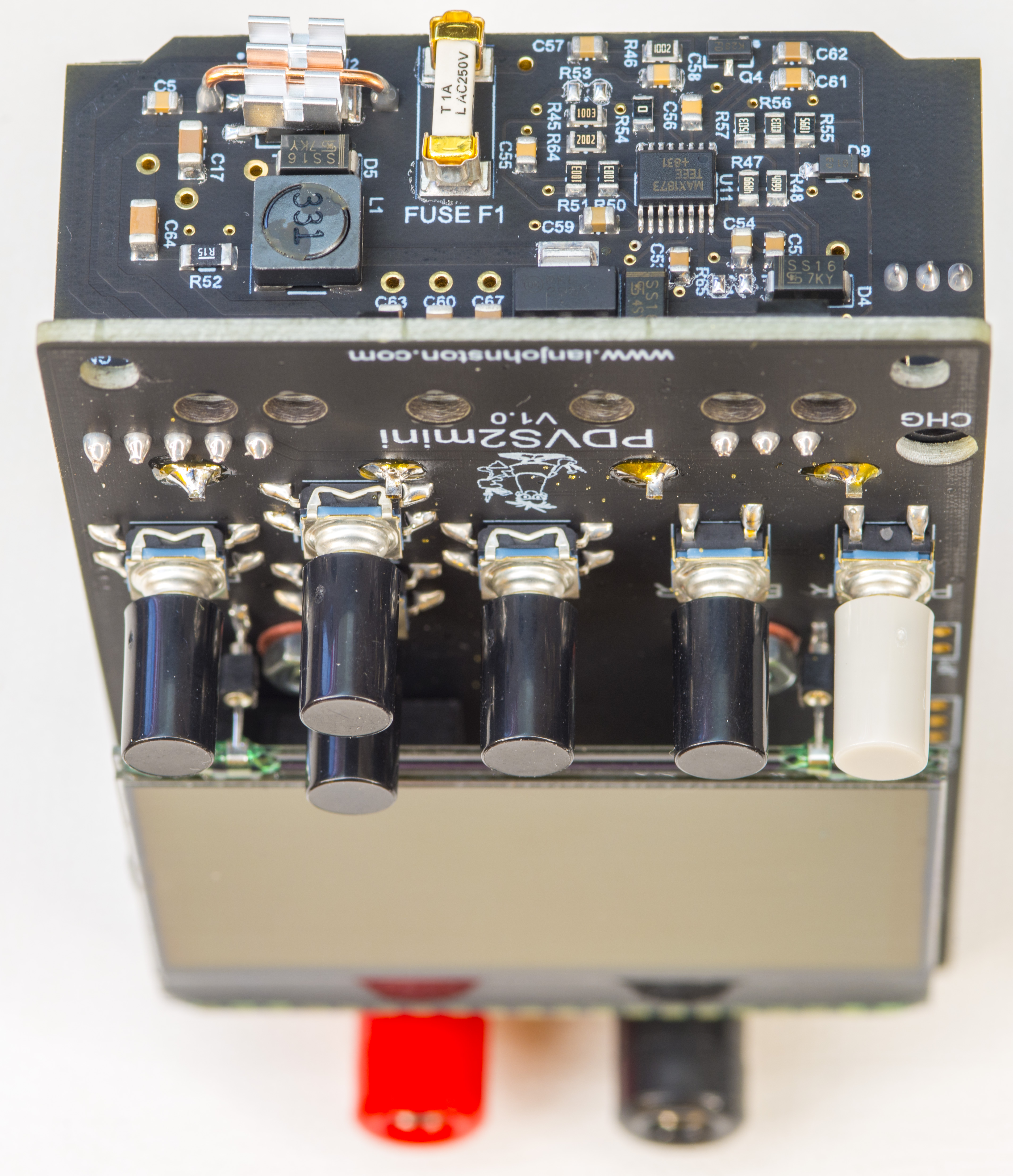
Apart from the possible introduction of noise depending on your DC power source......and by example running at 20Vdc at the power jack sees the output vary by about 10uV (1bit !) eventually due to the extra internal heat being generated.
On disconnecting the DC input it takes approx. 30mins for the unit to return to it's normalized output.
I've tried to minimize this heat induced drift by mounting the LM399AH externally, it's under the LCD in it's own little 3D printed conductive PLA thermal cover.
Running off DC permanently then has it's issues per above, but is entitely safe. The MAX1873 battery management IC recognizes an external supply and once the battery is detected as fully charged it will cease charging completely and the DC supply is used to feed the rest of the circuit. The batteries remain in isolation effectively and are not in any way trickle charged.
I haven't had a Lithium-Ion battery leak yet and I have about 40 of them which have been charged, drained and left sitting for months on end in and out of PDVS's.
PS. This unit was never directly designed as a "reference"......it was designed as an adjustable precision voltage source, but with some capabaility of a reference.
Quote from my website "With a user adjustable range from a true 0V to 10Vdc and an accuracy/stability down in the uV’s it has a multitude of uses as a calibrator, reference & precision voltage source."
But TiN is right.........not a great idea to calibrate a 3458A with it........
I'll be in production soon with it.
Ian. -
Are you planning to add a remote control?
-
Are you planning to add a remote control?
It has a serial header and you can control it remotely from a PC already much the same as the PDVS2 with an appropriate adaptor......however, I will just be supplying the Ascii protocol used and not a Windows app (well, I might supply an EXE unsupported).
Ian.
-
It has a serial header and you can control it remotely from a PC already much the same as the PDVS2 with an appropriate adaptor......however, I will just be supplying the Ascii protocol used and not a Windows app (well, I might supply an EXE unsupported).
Thank. I did not notice the serial connector.
-
Hi all,
I have just made the first batch of units available in my online shop. Here:-
https://www.ianjohnston.com/index.php/onlineshop/handheld-precision-digital-voltage-source-2-mini-detail
Available worldwide with shipping via UPS courier.
Thanks,
Ian.
-
i am not sorry for kicking this topic back alive :-)
wow amazing product you made there Jan, all looks super professional
I really like to see some closeups of the mecanical implementation of the LM399
you say it is under the display ?
and inside 3D printed isolation case ?
the display looks like it can be taken out, so this detail could be revealed,
-
It is an amazing product. Mine does not seem to be drifting at all. The reason I must use the word "seem" is due to an interim calibration/adjustment for my 3458A. I wasn't careful enough and should have made more measurements and records. I confess to being a bit of a sloppy volt nut
-
i am not sorry for kicking this topic back alive :-)
wow amazing product you made there Jan, all looks super professional
I really like to see some closeups of the mecanical implementation of the LM399
you say it is under the display ?
and inside 3D printed isolation case ?
the display looks like it can be taken out, so this detail could be revealed,
Hi,
Here's the LM399 cover.........3D printed in conductive PLA, and grounded to the pcb GND via it's mounting screw, a pad and a ring around the LM399.

-
Spec of the conductive PLA from the datasheet:-
How Conductive Is It?
● Volume resistivity of molded resin (not 3D Printed): 15 ohm-cm
● Volume resistivity of 3D printed parts along layers (x/y): 30 ohm-cm
● Volume resistivity of 3D printed parts against layers (z): 115 ohm-cm
● Resistance of a 10cm length of 1.75mm filament: 2-3kohm
● Resistance of a 10cm length of 2.85mm filament: 800-1200ohm
Ian. -
Are there any long-term stability measurements? For example calibration over several years.
-
Are there any long-term stability measurements? For example calibration over several years.
The closest I have is a customer who bought one in Oct. 2019, and then damaged it in Oct. 21 and it was sent to me for repair. A protection diode was replaced and then a full re-cal.
Unfortunately, back in 2019 I didn't produce as full a cal cert as I do now, however, you can see the BIT COUNT changes I had made on the re-cal which will give you some idea.
As follows:-

-
The closest I have is a customer who bought one in Oct. 2019, and then damaged it in Oct. 21 and it was sent to me for repair. A protection diode was replaced and then a full re-cal.
Unfortunately, back in 2019 I didn't produce as full a cal cert as I do now, however, you can see the BIT COUNT changes I had made on the re-cal which will give you some idea.
Thanks. Comparing a few of the data points, I only see 1-2 counts correction.
If you place a few units in different storage conditions and record their calibration every few months, that could answer the "tba" placeholder for drift in your specifications to increase the (already high) value of your product.
Nitpicking: The certificate specifies 11 digits for voltage output which seems optimistic. Also, including some calibration/accuracy estimation of your 3458A would be helpful. -
The closest I have is a customer who bought one in Oct. 2019, and then damaged it in Oct. 21 and it was sent to me for repair. A protection diode was replaced and then a full re-cal.
Unfortunately, back in 2019 I didn't produce as full a cal cert as I do now, however, you can see the BIT COUNT changes I had made on the re-cal which will give you some idea.
Thanks. Comparing a few of the data points, I only see 1-2 counts correction.
If you place a few units in different storage conditions and record their calibration every few months, that could answer the "tba" placeholder for drift in your specifications to increase the (already high) value of your product.
Nitpicking: The certificate specifies 11 digits for voltage output which seems optimistic. Also, including some calibration/accuracy estimation of your 3458A would be helpful.
First of all, those numbers are most impressive.
There's nothing wrong per se with 11 or more digits, but w/o estimate of the measurement error, they are a bit questionable. Sure, we can look up the uncertainty Agilent promises to better with the 3458A, but that tells us little about your unit nor how much additional error is introduced when measuring the calibrator (I'm sure there are codified / documented best practices, but an ad-hoc approach might be to use an example unit, measure it's voltage a number of times over multiple days, inverting polarity and calculating the standard deviation from that -- that at least gives a hint about the quality / reproduce-ability of the measurement procedure). -
Thanks guys, some good points there.
My automated procedure just logs directly what the 3458A output gave at the time with an NPLC of 100.
Are those numbers reproducable?......no, certainly not at 11 digits, but i figured if thats the numbers the 3458A sees then thats what i record. To be honest, i didnt think twice about it.
I'll look into pulling those digits back on the cal certs on future ones, or maybe adding a statement to the certs.
Thanks,
Ian. -
Or just remove everything after 7th digit and call it a day.
I wonder if Ian considering to use new 1399 reference in PDVS "3" mini version?
-
I wonder if Ian considering to use new 1399 reference in PDVS "3" mini version?
Hmmmmmm!
Ian. -
Thanks guys, some good points there.
My automated procedure just logs directly what the 3458A output gave at the time with an NPLC of 100.
Are those numbers reproducable?......no, certainly not at 11 digits, but i figured if thats the numbers the 3458A sees then thats what i record. To be honest, i didnt think twice about it.
I'll look into pulling those digits back on the cal certs on future ones, or maybe adding a statement to the certs.
Thanks,
Ian.
I would be inclined to leave all the digits there, might even help identify minor drifts with the 3458A... there are "only" 5 decimal places on the PDVS2mini, with the last one known to have a little rounding due to DAC conversion, I really wouldn't worry about it, people will only be looking up to the 5th/6th decimal place I expect, the rest is for your own records. -
I would be inclined to leave all the digits there, might even help identify minor drifts with the 3458A... there are "only" 5 decimal places on the PDVS2mini, with the last one known to have a little rounding due to DAC conversion, I really wouldn't worry about it, people will only be looking up to the 5th/6th decimal place I expect, the rest is for your own records.
NIST would have trouble with 11 digits......heading into superconducting JAWS territory.
9dp's on my certs are not stable, not reproduceable so kinda pointless being there.
If i run the autocal again the numbers wouldnt be the same.
The PDVS2mini isnt that stable......so TiN is right, 7 digits will do.
It's a Precision Voltage Source, not some high grade piece if metrology gear.
Gotta be totally honest/clear when selling.........
Ian.
Update, it's fixed (example):-Code: [Select]volts10.Text = Format(Val(txtr1aBIG.Text), "#00.0000000") -
Has anyone experimented using the PDVS2mini and a resistor voltage divider to generate much smaller voltages or with an external circuit to make a precision current source?
-
Hi @IanJ !
Two quick questions.
1. Why aren't you used AD 5791 for DAC?
2. The schematics can be obtained, in order to make an output amplifier that can be driven by PDVS2mini?
Thank you!
-
Hi @IanJ !
Two quick questions.
1. Why aren't you used AD 5791 for DAC?
2. The schematics can be obtained, in order to make an output amplifier that can be driven by PDVS2mini?
Thank you!
The AD5791 is very expensive, and requires a more complicated power supply circuit. Easy to do but affects the BOM.
The schematic diagram is not available I am afraid.
Ian. -
Indeed, is more expensive and now is "unobtanium".
There is a project with AD5791 as a calibrator but max 20 uV step.
I'll see how I will extract output of the calibrator for interfacing an external amplifier.
Thank you! -
The AD5791 is very expensive, and requires a more complicated power supply circuit. Easy to do but affects the BOM.
The schematic diagram is not available I am afraid.
Ian.
On that topic, another question is why not use a discrete PWM DAC ? It looks like some of the old HP voltage sources use that design to get 6.5 digit accuracy. I'm only a hobby tinkerer, so if that's a silly question feel free to say so.
I'm thinking of making a hobby grade programmable source as learning exercise with a decent 10v reference like LT1021C, with a discrete PWM DAC driven by a STM32, analog switch like ADG1611 and a low pass filter. -
Heh, DAC schematic from 3245A. This might explain it

Still going to tinker with a simpler version and see how I go
-
About a month Ian has posted on Youtube a repair video of 3246A - https://www.youtube.com/watch?app=desktop&v=0EPc8ttbU3Q
-
is the schematic+fw available for this to homebrew one?
-
is the schematic+fw available for this to homebrew one?
https://www.eevblog.com/forum/metrology/new-pdvs2mini-dc-voltage-reference-from-ian-johnston-reviewed/msg4287775/#msg4287775
-
Just saw this on Ian's PDVS2mini page (https://www.ianjohnston.com/index.php/onlineshop/handheld-precision-digital-voltage-source-2-mini-detail):
"I have decided for logistical and health reasons to stop making PDVS2mini’s permanently.
If you’d like to purchase the rights to the design, all design files and my remaining stock of parts then please contact me.
The PDVS2mini is a very successful and well respected product, it deserves to live on.
Business enquiries only" -
Oh noes, I've always wanted to get one and missed out on the last round. Too bad, hope you're ok Ian. Take care.
-
Yeah I am fine.....health wise nothing drastic just can't hover over the workbench for days-on-end anymore.
I've had a few enquiries thus far and options to look at.......hopefully one of them will work out and the PDVS2mini will continue.
Ian. -
Whew, glad to hear your health issue is nothing drastic!
Maybe you could find someone to do the harder parts like populating the PCB. I also think it would still sell at a higher price point, so you could take your time and make fewer? -
I've been looking at buying one for a couple of years but I thought you had stopped selling them post covid. I should have used the "email when available" link, my bad. Glad its nothing too serious thats stopped you and hope you enjoy your other interests.
-
Woah, all the best Mr. Johnston!
Absolute bummer though, this product is amazing and deserves to be continued! And I was waiting for the new production..
Wish I could help with this, but I'm afraid I lack the experience. Hopefully a new partner can be found soon! -
Just saw this:
"The design rights to the PDVS2mini has been SOLD.
Forwarding information for the new manufacturer will be published soon." -
Just saw this:
"The design rights to the PDVS2mini has been SOLD.
Forwarding information for the new manufacturer will be published soon."
Nearly 5 years of home production of the PDVS2mini and 40yrs in the oil industry (mostly electronics related) it's time to retire, part health issues and part "it's time".
The demand for the PDVS2mini has never been higher and I think it will be in great hands, so please give them some time to get their ducks in a row, keep your eye on my website for updates.
For me, I am still doing a couple days a week in oil just for a wee while so the folks taking over my work can make good.......so lets, for the moment, call it semi-retirement.
Meanwhile I am forging ahead having fun with my YouTube channel and test instrument repairs.......so if you have any faulty gear you don't need then please contact me.
Ian.
-
Ian, this enhanced picture of what's going on with you is encouraging for those of us who tend to assume the worst. Thanks for the update. All the best!
-
why not release this as an open source project?.
-
why not release this as an open source project?.
And why would he?
It is a low cost calibrator. Apart from Ian making a nice and elegant design, for users of device 99% of utility of buying it was fact that Ian kept calibrated KS3458 that he calibrated devices with. And he did a top notch job, too.
You were buying calibration, mostly, not device per se.
Without proper calibration it's not very useful...
Without proper calibration it is just a source of stable voltage.
And also, people that do the hard work should get paid for it. -
Ian deserved to earn some money by selling his design to someone that was willing to continue the work and ensure that people could still buy the units, and as mentioned, building the thing is only half of it, a decent calibration of the PDVS2mini is the critical bit there.
-
why not release this as an open source project?.
If he was shutting his business down completely, then that would be ideal. It benefits the community and allows existing owners to maintain their units.
But as 2N3055 explains, a large part of the value of such a device is in the calibration which your average DIY builder would not have access to.
For as long as it is a viable product, it makes much more sense to sell the business/IP as a going concern and have someone continue the manufacture and calibration. While the market is somewhat limited, there was clearly demand as Ian would quickly sell out of each production batch. It took me a few in-stock notifications before I had an opportunity to grab one for myself. His pricing was very fair, and I don't think anyone reputable could provide them significantly cheaper. -
why not release this as an open source project?.
There are other projects as open sources.
One of them is here - https://www.elektormagazine.de/labs/voltage-current-calibrator-0-to-10v-and-0-to-40ma-0001
with atempts to replicate here : - https://www.eevblog.com/forum/testgear/elektor-voltage-current-calibrator-project/
But as you can see and guys here explain before me, the main issue is the calibration of such device, even the methodology for aquiring repetable results is not easy.
-
Ian starts talking a bit about his now sold PDVS2mini design in this podcast starting here:
https://youtu.be/kTpmiK5p_Wc?t=1152
New owners are making some improvements:
https://youtu.be/kTpmiK5p_Wc?t=1923
-
For the (now discontinued) PDVS2, the manual says that there is a simple ascii protocol available on request. I have one of these, and would like to be able to program a fairly complex sequence of voltage steps far beyond the 5 steps provided by the windows electable. Is that still available or would I need to contact the new owners of the PDVS2mini?
I'm very happy with this as a manually-programmable voltage source, but (in contrast to the observation in the podcast that "everyone was just using it for it's basic functionality" I also want to use it in an automated test setup to examine the performance of voltage-controlled oscillators; this requires around 100 steps for a full test. -
Go to my website, online shop and look up the manual for the PDVS2mini, the comms protocol is published there……which is almost identical to the PDVS2.
I will provide the actual protocol for the PDVS2 on this thread later today. -
Perfect, so <KeyVoltage,0,1.23456> is all it takes in terms of commands(!) wonderful
-
Perfect, so <KeyVoltage,0,1.23456> is all it takes in terms of commands(!) wonderful
There are slight changes depending on firmware version, but here's the protocol text doc for the PDVS2.Code: [Select]PDVS2 Serial Protocol (PVDS2 firmware 3.00)
===========================================
INTERFACE = USB (FTDI USB Drivers - http://www.ftdichip/Drivers/VCP.htm)
BAUD: 250k,N,8,1
A simple bi-directional ascii based serial data protocol
Rate = Data from PDVS2 to PC is sent every 110mS
Format to PC:- VR0,0,12345
Format from PC:- <KeyVoltage, 12, 1.23456>
The following details all the data being sent from the PDVS2, and only a partial listing of the data from the PC.
PDVS2 OUTPUTS TO PC:
========================
KV,0, Output Voltage of PDVS2
BV,0, Battery Voltage or DC Input Voltage
BVFM,0, Battery Voltage Feed Mult
OVF,0, Output Voltage Feedback
OVFM,0, Output Voltage Feedback
dacZ,0, DAC Zero Cal
dacS,0, DAC Span Cal
BC,0, Message = DC Input - Charging, DC Input, DC Input - Full, Running on Batteries, Battery Charge high mA!
BLI,0, Message = Status - Low, Status - Ok
Mode,0, Message = Main Menu, Normal, Calibration, Settings, Playback, Ramp
VA0,0, Volts Auto Set[0]
VA1,0, Volts Auto Set[1]
VA2,0, Volts Auto Set[2]
VA3,0, Volts Auto Set[3]
VA4,0, Volts Auto Set[4]
TA0,0, Time Auto Set[0]
TA1,0, Time Auto Set[1]
TA2,0, Time Auto Set[2]
TA3,0, Time Auto Set[3]
TA4,0, Time Auto Set[4]
AC,0, Autocount
AMR,0, Message = Running, Stopped
VR0,0, Volts Ramp Set[0]
VR1,0, Volts Ramp Set[1]
VR2,0, Volts Ramp Set[2]
VR3,0, Volts Ramp Set[3]
VR4,0, Volts Ramp Set[4]
TR0,0, Time Ramp Set[0]
TR1,0, Time Ramp Set[1]
TR2,0, Time Ramp Set[2]
TR3,0, Time Ramp Set[3]
TR4,0, Time Ramp Set[4]
RC,0, Ramp count
RMR,0, Message = Running, Stopped
BMIM,0, Battery Monitor IC Mult
BI,0, Battery current
AL,0, Autoloop
RL,0, Ramploop
SC2,0, Seconds2
dacZ2,0, DAC Zero Cal Dac2
dacS2,0, DAC Span Cal Dac2
VRS,0, Vref Switch
CMS,0, Cal Mode Sub
OUTPUT FROM PC TO PDVS2:
========================
<KeyVoltage,0,1.23456> Voltage requested to output from PDVS2
<VrefSet,0> Vref setting, 0=10v mode, 1=2v mode
Ian Johnston -
I fumbled my PDVS2mini taking it off the shelf and dropped it onto my bench. Thankfully, it seems to have survived undamaged. I decided its front panel needed some protection from me (and also from the dust that settles on anything I don't touch twice a day).
This case has a nice close fit, a satisfying magnetic closure, and a storage slot so I don't lose the charging cable. (I should find where I stashed the cal sheet and stick that in there, too.) I used PETG for impact resistance and strong layer bonding.
If anyone has the same butterfingers problem and wants to make their own, I've attached the .step file.
Hardware is:- M2.5x25 with nylon lock nut, qty 2 (for hinge pins)
- 6x2.7 mm magnet, qty 4 (commonly sold as 6x3 mm, I designed for the actual thickness of the ones I have)