-
#25 Reply
Posted by
Vgkid
on 24 Apr, 2016 01:52
-
Nice job. Currently reading through the uploaded documents.
-
#26 Reply
Posted by
nidlaX
on 25 Apr, 2016 23:46
-
Wow, nice bright LEDs you got there. Reminds me of gaming PCs nowadays. O0
-
#27 Reply
Posted by
TiN
on 26 Apr, 2016 04:18
-
Most still have stock resistors which is way too low for modern leds. It will be fixed, be sure

.
Initial linearity data, if you want to call that "linearity".

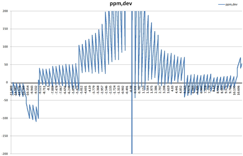
-12 to 12VDC in 1mV steps, measured by 3458A. There are two measurements, with first sample disregarded, 0.5 seconds delay, second sample used for the point.
You can see it's not good, so will be investigating.
And here's another run, just -11 to -9V
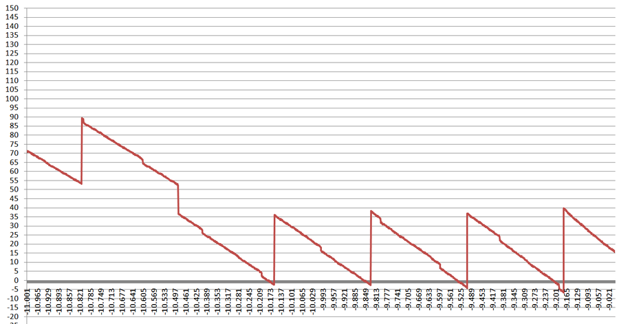
I'm likely to plot same graph, but with LS DAC removed, to get linearity of coarse 6-bit DAC as first step.
Then we will think of what to do with LS DAC. Maybe add bodge board to interface some modern DAC, like LTC2756 instead of original AD7534, if that would be the sticking point..
-
#28 Reply
Posted by
amspire
on 26 Apr, 2016 04:49
-
It doesn't look too bad - all I am seeing there is that the MSD resistors need calibrating, and cal for the DAC is a little too high. After calibration, it looks like it will be within a few PPM. Whether the resistors in the DAC drift will be the question then.
Do you have a calibration procedure?
-
#29 Reply
Posted by
TiN
on 26 Apr, 2016 04:53
-
Yes, I have the procedure, but I'm not sure I fully understand it. I'll post it here later on to confirm few things.
-
#30 Reply
Posted by
amspire
on 26 Apr, 2016 05:43
-
Yes, I have the procedure, but I'm not sure I fully understand it. I'll post it here later on to confirm few things.
Calibrating the R-2R networks are not the easiest things - two adjustments per bit. Every adjustment can affect every other adjustment.
-
#31 Reply
Posted by
Kleinstein
on 26 Apr, 2016 10:41
-
The nonlinearity looks a little strange: besides the large steps with constant spacing there seem to be smaller steps that do not really line up with the rest. Most of it still looks like a problem with the MSB ADC.
So I am afraid there is more needed than just adjusting the MSB ADC and the scale of the LSB ADC.
-
#32 Reply
Posted by
TiN
on 26 Apr, 2016 10:45
-
You meant DAC, surely
That is one of reasons why I want test MS DAC separately, to see if the issue there.
-
#33 Reply
Posted by
Dr. Frank
on 26 Apr, 2016 15:57
-
The trimming of the 6 MSB of the DAC is very coarse, about 2500/5000ppm for 2R or R, respectively.
Therefore, trim resolution and minimum linearity is worse than 10ppm, at best.
So the root cause could simply be a mis - adjustment.
Otherwise, I would first check, if the switches inside the potted case provide exact 0V and 5V to the six 2Rs.
Simply measure on pins 2,3,4 and 13,14,15 of the connector, when switching different values.
A nicer and more precise R2R - DAC is inside the Fluke 3330B, maybe interesting for understanding trimming scheme, and so on.
Frank
-
#34 Reply
Posted by
amspire
on 26 Apr, 2016 16:45
-
The trimming of the 6 MSB of the DAC is very coarse, about 2500/5000ppm for 2R or R, respectively.
Therefore, trim resolution and minimum linearity is worse than 10ppm, at best.
You are right. You would expect that at least the 3 or 4 most significant bits would have a much lower adjustment range. Trusting 5000ppm + 2500ppm to two trimpots for the MSB accuracy is scary. Just a 0.1% drift in both pots could cause up to a 7.5ppm error. It is a preventable source of error. Fluke would never do that.
So the root cause could simply be a mis - adjustment.
Otherwise, I would first check, if the switches inside the potted case provide exact 0V and 5V to the six 2Rs.
Simply measure on pins 2,3,4 and 13,14,15 of the connector, when switching different values.
The dac switches could have a significant resistance. Ideally the switch resistance should be less then about 40 milliOhm for the MSB - but they could be deliberately using a higher resistance and relying on the switch resistance being fairly constant. With the potting, they could be even combining MOSFET switches with a small temp compensation network. So depending on the other voltages in the R-2R chain, you could see voltage drops across the DAC switches as high as as 0.1mv but hopefully it is lower. The R-2R calibration will compensate for any switch resistance, so resistance is OK, as long as it is constant to about 40 milliOhms over temperature for the MSB down to within about 0.6 ohms over temperature for the LSB.
A nicer and more precise R2R - DAC is inside the Fluke 3330B, maybe interesting for understanding trimming scheme, and so on.
I am sure Fluke would do it right. I will have a look at the 3330B manual just to see how they do it.
-
#35 Reply
Posted by
manganin
on 12 Jun, 2016 21:21
-
-
#36 Reply
Posted by
acbern
on 13 Jun, 2016 09:20
-
Comes with manuals, i dont think its too bad a price actually.
-
#37 Reply
Posted by
TiN
on 13 Jun, 2016 10:09
-
Price is OK for such box. I paid very similar for my broken one and not regretting it. It's rather easy to service this calibrator with its minimalistic design, and also much smaller to big expensive brothers from Fluke/Datron.
-
#38 Reply
Posted by
acbern
on 16 Jun, 2016 18:27
-
It sold for that price.
-
#39 Reply
Posted by
TiN
on 16 Sep, 2016 13:30
-
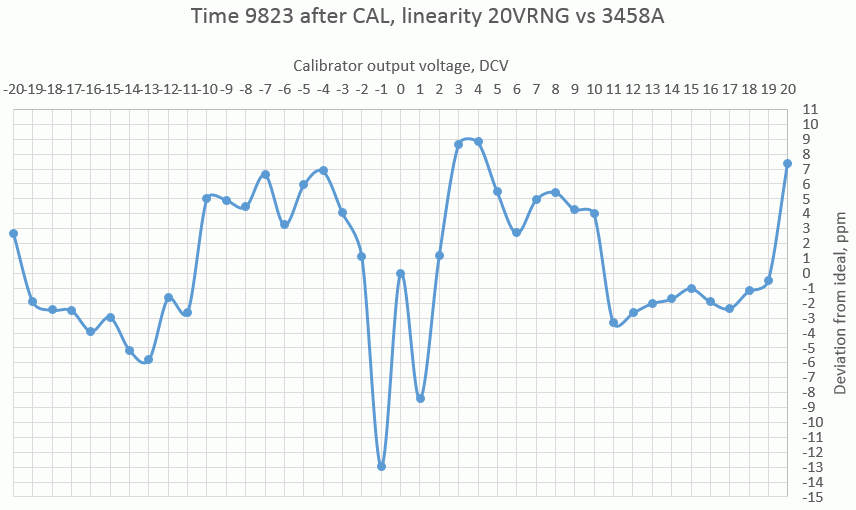
Sorry for revive, just got 9823 finally assembled, adjusted linearity R2R network in DAC and calibrated vs 3458A (+/-1.5ppm DCV, +/-4ppm ohm).
Did quick manual linearity test on 20V range, and it does not look that impressive AFAIK.
Still lightyears better than before, though
Calibration procedure is PITA as well, trimpots definition and location of actual hardware I have does not match either of two manuals.
Three of more times after whole adjustment (each range and each function) CAL ROM got borked (giving ERROR 7 on power on, with everything locked). Smart me, I had original CALROM backed up, so just reverted it and recal again (another few hours pushing knobs

).
-
#40 Reply
Posted by
mimmus78
on 04 Oct, 2016 22:09
-
Hi TiN, I have a 9823 too ... also mine was broken, going up and down of 100ppm and resetting every 5 minutes.
Lucky me just fiddling with the eurocards have fixed it and now is stable at 2ppm of my K2001 and not resetting anymore.
One strange thing to me is it takes more the 2h to reach it stable point ... this is written on the manual but I usually expect less time for warming up than the one specified on manual. Maybe because reference and ADC DAC are potted it takes some more time for both to reach the final temperature (actual drift from cold to worm is 15ppm). Do you noticed if your unit act like this?
Do you have the processor board schematic page? I got the technical manual but this page is missing and I only have processor board layout.
Thanks for your repair article over this, your work is quite good.
-
#41 Reply
Posted by
TiN
on 05 Oct, 2016 04:30
-
There is no oven on reference for 9823, so 2hours, better 4-8h to stabilize internal temperatures sounds reasonable for me. There is no ADC in 9823.
I did not test for warmup time, as I always have it turned a day prior to actual measurements, and 1hour if room temperature change more than 3°C.
I'll check on schematic page, I think I have it. After I scan it, I'll update the article.
-
#42 Reply
Posted by
mimmus78
on 05 Oct, 2016 15:52
-
Well yes I mean DAC not ADC :-).
Anyway this 15ppm drift is still from some sort of warming up ... maybe one day I will check if is reference drifting or some other stuff.
-
#43 Reply
Posted by
TiN
on 06 Oct, 2016 19:16
-
Ok, my DMM got free tonight, so i hooked it to cold MFC and started logging at 10VDC. First it was +4.7ppm, raised a bit to 5.x ppm in 10 minutes and now dropping down (+1.6ppm now after 15min). I'll post the graph tomorrow.
-
-
Many years ago I did a few bits of work for Time, including redesigning one of their potted reference blocks - replacing a very complex hand-rolled chopper amp with a more modern single chip device.
They usually used zeners for references, which they aged and characterised themselves over many months.
Many of their designs dated back from before you could buy precision parts easily so there were many hand-made circuit elements, that lasted way after they could have been done using off-the-shelf parts. These were considered "special sauce" which was why they were potted.
-
#45 Reply
Posted by
mimmus78
on 06 Oct, 2016 21:53
-
I still have this puppy open so I attached a thermocouple to the reference pot stuff and verified that the power on drift is due to this guy warming up. My unit when turned on just go down ... except for the very first minutes I never checked.
I will soon have some GPIB stuff ... so I hope to characterise this behaviour.
Inviato dal mio Nexus 6P utilizzando Tapatalk
-
#46 Reply
Posted by
TiN
on 07 Oct, 2016 04:12
-
Here you go:
Warm-up logI had logging issue after 4am, so restarted log in morning with reset DCV output to 0V and back 10V.
So it's about 10ppm total delta from cold state to warmed up, which seem to be inline with your result.
-
#47 Reply
Posted by
mimmus78
on 09 Oct, 2016 22:13
-
And this is mine 9823 warm-up curve, all reading by a K2001.
-
#48 Reply
Posted by
mimmus78
on 22 Jan, 2017 00:01
-
So after few weeks my unit developed another intermittent series of problems.
Those problems where:
- output went crazy now and there
- calibrator has also some problems trowing "operator error" even when set to resistor functions and no leads where connected
- started again to auto-reset.
So I decided to replace the PIA too.
After replacing those two chips it seems:
- the "DAC system" is still missing some bit now and there but it's really not so often as was before
- auto-rest and unjustified "operator error" are gone
Replacing PIA seems to have cured some of my problems but not all.
I also just discovered problems with the
GPIB too.
Every time someone speaks to the bus the calibrator reset.
GPIB interface is also not working.
The saga will continue ...
