Hey guys, this afternoon I put together a little AM modulator for aligning and testing vintage AM radios, after playing around for a couple of hours I got something that works reasonably well, so I would appreciate any suggestions to improve this.

Schematic
http://u.cubeupload.com/Chryseus/xtw4kN.pngForgot to mention supply is 15V to gnd.
Output, I actually improved this a fair bit by adding 1k in series with the 2.2u
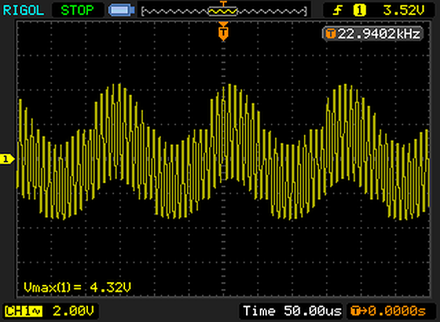
I do have a few specific questions:
What would you consider the best option for the carrier oscillator, 100kHz to 10MHz sine?
The loss in my isolation transformer is very high, what other methods could I use, optical ?
Would I be better off using a higher gain BJT than a JFET, assuming my sources are low impedance ?
Repectfully, what you have created is not amplitude modulation. It appears to be simply a summation of the audio and carrier signal. With AM, the carrier magnitude is varied with the audio. With your circuit, the carrier is simply shifted up and down with the audio, at roughly the same magnitude.
Take at look at the AM waveform on this wiki page, and compare it to your scope waveform to see the difference.
https://en.wikipedia.org/wiki/Amplitude_modulationThe choice of the carrier oscillator depends on what test frequency you want to use for your radio work. If you want to inject the signal into the IF of the receiver you're working on, such as 455kHz. Or, you might want to inject at the RF input, so the test frequency should fall within the receiver's frequency range.
Ahh yes I see what you mean, guess I have more experimenting to do

I built an AM modulator circuit for class use in my last job (technician at a UK university) using an MC1496 IC.
http://www.tsc.uc3m.es/docencia/LEC/manuales/mc1496rev4f.pdfI just used the application circuit in the data sheet and made sure that the power supply to the circuit was properly decoupled (otherwise the regulator oscillates badly).
Works fine.
David.