Find a datasheet with an error in it?
Rant about it here....
Find a datasheet with an error in it?
Rant about it here....
Datasheets with typos and graphic errors: plenty.
But the one that really brings my blood to a boil is CD4046/MC14046/74HC4046.
The original data sheet was apparently written before PLLs were a big thing, and is deliberately obtuse on how to design the Loop Controller (aka Loop Filter).
The RRC filter in the DS will never work for a Type 2 PLL, but was copied from the original DS to the Motorola DS and uncritically propagated to the next generation 74HC4046 DS.
I had to go out and find "Phaselock Techniques" by Gardener ($100) and spend a week reading before I realized that the DS was lying to me (plus a TI app note, apparently written by an apprentice with very limited knowledge of PLLs).
No wonder that so many people are frustrated with this part.
Someone didn't check if their vector graphics formatted correctly. Try implementing this example circuit as it looks like it's shown.. Good luck...
What? All it needs is a bidirectional transistor and a resisuctor!

Someone didn't check if their vector graphics formatted correctly. Try implementing this example circuit as it looks like it's shown.. Good luck...
What? All it needs is a bidirectional transistor and a resisuctor!
I can't find that "resisuctor" anywhere. Just like TI to use obsolete parts in their examples!
I can’t name the chip, but it comes from a major brand. Has a Vcc, a Vbackup from coin cell and a Vmain.
Data sheet says Vmain is meant to take power from eg a LiPo when Vcc is off. Original application guide said same.
Some time later we had grief with data corruption in backup SRAM and looked for updates. Data sheet info for Vmain hadn’t changed. No erratum issued. Application guide quietly changed to say ‘connect Vmain to ground.’ Assholes
Less of an error but more asshole move.
Some chips in the STM32H7 had a bunch of stuff changed in the datasheet trough a chip revision. Things like ADC clock dividers changed, registers for USB moved around etc... but most importantly it changes the clock speed of the CPU from 400MHz to 480MHz.
So if you designed in that chip and the distributor you bought from had some old stock you might get the old revision chip while using the latest datasheet. I caught this luckily (likely by accident when looking at errata for some problem), however i had to order chips from 3 different distributors before i found one that had the new chips in stock, so all my prototypes would be the same new chip. Since the partnumber has not changed you can't specifically order the 'new one', all you can do is buy it and check the extra revision marking on the chip.
Not sure if the old revision chips could already run at 480MHz and they just changed their mind, but the erratas and chanelogs are worded in a way that suggest the do only work to 400MHz. Tho a 400MHz MCU most likely overclocks just fine to 480, they have a lot of safety margin. But still the hardware register changes will break most firmware.
[Edit: No, in fact it's the default initialization code that's to blame, not the Datasheet. See posts below]
CH32V003 MCU Reference Manual (V1.3), it states that the reset value of bit 15 ("PA12_RM") in register AFIO_PCFR1 is "0", while in fact it is "1".
If you're going to use pins PA1 or PA2 as regular GPIOs, you'll have to change it back. Ask me how I know

CH32V003 MCU Reference Manual (V1.3), it states that the reset value of bit 15 ("PA12_RM") in register AFIO_PCFR1 is "0", while in fact it is "1".
If you're going to use pins PA1 or PA2 as regular GPIOs, you'll have to change it back. Ask me how I know
Are you
sure about that?

I have a design using a CH32V003 that uses both PA1 & PA2 as GPIO and I've never had to touch the AFIO_PCFR1 register, which implies that the default reset value of PA12_RM is indeed zero.
Also, v1.5 of the Reference Manual (published recently on 20th July) has no changes to the description of PA12_RM compared to v1.3.
CH32V003 MCU Reference Manual (V1.3), it states that the reset value of bit 15 ("PA12_RM") in register AFIO_PCFR1 is "0", while in fact it is "1".
If you're going to use pins PA1 or PA2 as regular GPIOs, you'll have to change it back. Ask me how I know
Are you sure about that? I have a design using a CH32V003 that uses both PA1 & PA2 as GPIO and I've never had to touch the AFIO_PCFR1 register, which implies that the default reset value of PA12_RM is indeed zero.
Also, v1.5 of the Reference Manual (published recently on 20th July) has no changes to the description of PA12_RM compared to v1.3.
Absolutely sure, and verified yet again after reading your reply.
Here's the relevant part of my setup code:
    // Enable clock for ports A,C,D
    RCC->APB2PCENR |= 0x00000034;
    // For PA1/2 as GPIO, disable Crystal functionality
    AFIO->PCFR1 &= ~0x00008000;
    GPIOD->CFGLR = 0x44444441; // PD0 = Red
    GPIOA->CFGLR = 0x44444144; // PA2 = Green
System clock is the default internal oscillator. The green LED connected to PA2 is controllable (PA2->Resistor->LED->GND). If I comment out the AFIO line, it's always off.
If there's another explanation, I'd love to hear it, since I'm just beginning to learn this IC.
Chip is CH32V003F4P6 (TSSOP20). Only tried one unit so far. I'm using MounRiver Studio 1.85, but I'm skipping the default HAL functions to get a better grasp of the low-level stuff.
Absolutely sure, and verified yet again after reading your reply.
Also using TSSOP20 package here, with the HSI oscillator, and not using the SPL/HAL, nor even the default start-up code (I changed it not to call HAL's SystemInit() and to disable PFIC HPE).
I can't 100% state that the reset value in AFIO_PCFR1 is actually zero for me - I could probably look with a debugger - but whatever it is, I never change it (nothing in my code touches AFIO_PCFR1) and the PA1 & PA2 pins act as GPIOs for me (both are used as inputs). There is one difference in your initialisation to mine, but it would be weird if that made a difference - where I enable the peripheral clocks in RCC->APB2PCENR, I enable AFIOEN in addition to the necessary GPIO ports.
Maybe, and this is just speculation, there could be a bug where if you don't enable the AFIO peripheral clock, it doesn't initialise the default value of AFIO_PCFR1 properly?
Or, perhaps this was a hardware bug in an initial revision of the chips? What are the markings on your chips? Mine are marked '412309C51'.
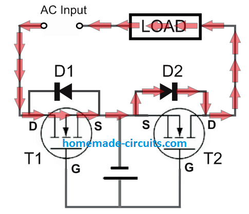
This utter nonsense from TI
You could say what you're reacting to...
There are several misrepresentations, but the basics are fine i.e. it turns on when it's on and it's off when it's off. They don't mention diode drops so they might as well not exist.
There is an awful lot I see, still, of people putting diodes in parallel with MOSFETs, even with the new fangled symbols with the back diode drawn beside the thing already. Well, there's no accounting for poor education I'm afraid; no amount of my saying appnotes are trash, has made a lick of difference, nor complaining to the manufacturers that keep representing things so poorly. The only thing we can do, is guide others to the truth, as we meet them, preferably with humility and grace. Whether they figure out, or accept, the truth, is their own matter.
Tim
This utter nonsense from TI
You could say what you're reacting to...
He could, but it doesn't take long to figure out.
They show current flowing through the parasitic body diodes of FETs which are turned on

I mean, it will happen, at some current (I > Vf / Rds(on)). It could happen. Not that it will necessarily. It's not a bald faced lie; like I said, it's a misrepresentation.
Tim
It's a lie by omission, as they fail to show the main principle of operation.
And it cannot really happen, because in such case the current would flow through both paths simultaneously.
Maybe if the SSR is particularly "underdriven" it could occur that both FETs are at their threshold and the "forward" one conducts by its body diode with negligible channel conduction (but still not zero) while the "reverse" one cannot so it heats up and increases its channel conductance thusly, but I think we are straying further and further from the fundamental principle

This utter nonsense from TI
You could say what you're reacting to...
There are several misrepresentations, but the basics are fine i.e. it turns on when it's on and it's off when it's off. They don't mention diode drops so they might as well not exist.
There is an awful lot I see, still, of people putting diodes in parallel with MOSFETs, even with the new fangled symbols with the back diode drawn beside the thing already. Well, there's no accounting for poor education I'm afraid; no amount of my saying appnotes are trash, has made a lick of difference, nor complaining to the manufacturers that keep representing things so poorly. The only thing we can do, is guide others to the truth, as we meet them, preferably with humility and grace. Whether they figure out, or accept, the truth, is their own matter.
Tim
It's literally circled. Any significant current basically never passes through the body diodes as both MOSFETs are always in the same ON or OFF state. The only time some current could pass is during state change. It's an utter incompetency of someone who has drawn that as minimum. And as it's a "Basic SSR theory", this garbage has found it's way in many other places.
but the basics are fine i.e. it turns on when it's on and it's off when it's off.
Except it describes
HOW it works which is totally screwed up.
Also using TSSOP20 package here, with the HSI oscillator, and not using the SPL/HAL, nor even the default start-up code (I changed it not to call HAL's SystemInit() and to disable PFIC HPE).
Ugh, that's it. I stepped over the code from the top, and startup_ch32v00x.S does call SystemInit, which calls SetSystemClock, which tries to set the clock to 48MHz HSE and meddles with AFIO->PCFR1 along the way. I just didn't notice that call before. So you were right, it's not a Datasheet error. Thank you for helping clearing that up

IME at least as insidious are important things that are buried in a bunch of text so easily missed.
Here are a couple from TI and Microchip that have caught me.
On the Microchip one, this is literally the only place in the 350+ page datasheet that says these pins can't be outputs, and elsewhere they are listed as being I/O.
I was using this device as a sub for a very similar part that was unobtanium (PIC32MX174 vs. 32MX170), so never occurred that there may be different pin limitations. Luckily it was an easy track-hack.
Ugh, that's it. I stepped over the code from the top, and startup_ch32v00x.S does call SystemInit, which calls SetSystemClock, which tries to set the clock to 48MHz HSE and meddles with AFIO->PCFR1 along the way. I just didn't notice that call before. So you were right, it's not a Datasheet error. Thank you for helping clearing that up
SetSysClock() should only be calling one of the functions that changes PCFR1 if you have a SYSCLK_FREQ_*_HSE defined. You've probably still got the default SYSCLK_FREQ_48MHz_HSE defined at the top of the system_ch32v00x.c you're using with your code. Either comment it out (to use default 24MHz HSI) or uncomment one of the SYSCLK_FREQ_*_HSI.
I don't know why the hell they made SYSCLK_FREQ_48MHz_HSE the default in all their example code. Even their own eval board only has a damned 24MHz crystal on it and half the people using the MCU elsewhere probably want to use the HSI oscillator.
This nonsense is why I jettisoned all of their code and only use the register defines.

I'll just once more will stress significance of this MOSFET SSR nonsense. If I google "mosfet ssr" in incognito mode, google shows this or its derived garbage as 1st, 2nd and 4th results. And many beginners take it at face value
Its not an error exactly.. but the PCB Footprint is shown from the BOTTOM VIEW!!!??? Who does that?
https://www.kycon.com/Pub_Eng_Draw/STX-3000.pdf
Yep i had a similar thing happen to be with a SPDT relay, where they show a bottom view in the PCB layout drawing. WHY
This was not noticed until later on because the footprint still fit, but my NC and NO contacts were swapped around.