This project is buried in tons of posts.
Any hero willing to summarize it? If possible, what about asking a forum administrator to put a first post here with such information?
maybe someone has spare boards?
maybe someone has spare boards?
Iwanushk is that you from dangerprototype which unisolder 5.2 project ?
LOOL
Yes, that's me!
U r AWESOME 
All I did was sell some surplus boards, that's all, all the credits go to sparkybg
Are there schematics and PCB files about this project?
Do UniSolder by sparkybg supports RF soldering irons too? Last time I checked seems didn't support them. Please correct me if I'm wrong

maybe someone has spare boards?
I have a few questions ,as my english is not yet perfect,for me actually is not very easy to understand all this materials.
So let's start with some dumbass questions.
1)To power up this thing can i use an already made power supply ? maybe one like this ?
LRS-75-24
or is better to go with an simple power-trasformer?
2)Which power-trasformer i must to get ,something like this?
output : 30vac and 80va ? it must be less or more ?
3)In the original metcal the tip inside the hadler goes to sleep when the handler is inside the stand ,but here is the same as in the original metcal ?
Oh my GOSHSHSH !!!
no reply ,no one ,this for me looks like this project is almost more then death.
1, That type of power supply would work, the one in the photo is too small but LRS-75-24 would be enough.
2, The transformer I used was Farnell part number 1780865. 24 V 100 VA. There are plenty of other choices.
3, The magnetic stands saturate the tip and reduce the dissipation. That will work with this design if you use the right stand but you don't actually need to because this design uses directional couplers to detect forward and reverse power and the software on the PIC then makes a decision that the iron hasn't been used in a while and sets a low power mode. That mode keeps the tip cool for long life but is still hot enough that it can detect the heat loss (due to movement through the air) when you remove it from the stand.
There are PCB files and schematics available, they're attached way further back in the thread. I think many months ago and a couple of pages back there was a summary of what was on which posts.
Oki thanks you for the informations.
But i have some last questions to do.
Is the owner of this project don't care anymore about it ?
Because he must to make an update of the RF exit way on the pcb, to solder an connector-plug directly on the rf stage.
This will make an perfect swr tunning over the Power-Supply and the iron.
For example watch out this guy from youtube min 0:27 to 0:31 :
as you can hear, he claims to have problems with the hadler and in my personal opinion that problem is started by a wrong swr tunning caused by
the cable soldered on the RF powersupply.
We really need that update (At least i think this way)
I don't think that is likely to be a major problem. At these frequencies the odd impedance at the junction is only a very short length compared to the wavelength and it should really be fine. You could edit the files to add a connector footprint if you like but I am not convinced it will make a lot of difference.
Take a look at my page here:
http://randomfunprojects.co.uk/metcal.html and look at the table near the top of the page, you'll see the SWR of the tips themselves is not great when cold, reasonable when warm, and (by design, to regulate the temperature) very high when hot.
I don't think that is likely to be a major problem. At these frequencies the odd impedance at the junction is only a very short length compared to the wavelength and it should really be fine. You could edit the files to add a connector footprint if you like but I am not convinced it will make a lot of difference.
Oki maybe you are right,but i still can't figure out why the iron hadler of that guy is getting so hot,it's obviuosly an issue ...
However if the DIY Metcal Station is abbandoned by the owner ,it's useless to waste the proper time here.
This makes me sad ,because i was in love with this project

I don't think it's been abandoned, you will get answers to reasonable questions if you're patient but I think most people won't bother answering things they know you could find just by reading through the thread. Set aside some time to start at the beginning and read it all, note down post numbers with anything that looks useful. All the information is here, you can take the schematics, the PCB files and the software, change if you want to, and build it.
Oki maybe you are right,but i still can't figure out why the iron hadler of that guy is getting so hot,it's obviuosly an issue ...
However if the DIY Metcal Station is abbandoned by the owner ,it's useless to waste the proper time here.
This makes me sad ,because i was in love with this project
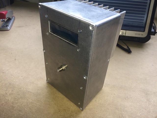
Thanks for linking my video on my build of the DIY Metcal (or MeltCal!). I know you wanted me to post my project however I'm not quite ready and there are a few things I wanted to get on video and photograph before presenting something here. I'm working on a new controller/PSU PCB (my build involves fitting the MeltCal into an radiation measurement instrument case that I bought off EBay) that will be AVR based, and is rather designed specifically for my build.
The other bit that I'm working on (slowly) is getting the v0.3 (plus modifications by Widlarizer(irc) in one of the feedback loops on the RF board) converted into Kicad along with a PCB layout.
@MRBadguy:
1)To power up this thing can i use an already made power supply ? maybe one like this ?
idpromnut: You sure can!
2)Which power-trasformer i must to get ,something like this? output : 30vac and 80va ?
idpromnut: I run my MeltCal at about 24-30VDC @ about 2-3A.
3)In the original metcal the tip inside the hadler goes to sleep when the handler is inside the stand ,but here is the same as in the original metcal ?
idpromnut: yes, but the catch is that the "mechanism" is in the hand piece holder, and not strictly in the RF board. The holder has a magnet near where the tip rests, and this changes the impedance of the tip which I believe makes the tip reflect more RF back to the RF supply which the supply detects and the built in feedback loop reduces the RF power to the hand piece.
I don't know whether this thread is still alive, but I was wondering if there were any boards available from the masterful creator of this project. This MX500 supply is something I would really like, only the real ones by Metcal are extortionately expensive.
Kind regards
D
Also, if the creator of this project is no longer on this forum, and there are no boards left, I would quite happily be willing to get a small production run made for anybody interested?
mamalala is still on this forum occasionally according to his user page: "Last active 2016-10-13, 08:51:25" In the past he's been happy for people to get boards made, there have been at least three batches over the lifetime of this thread.
You'll probably have to hunt through the thread to get the latest build files but all the information is in there.
Yes, thank you.
I have just had a chat with him, and he has no more boards left. I have had a look through the more recent posts, and people don't appear to have made any in any significant quantity. I will have another look but, as I say, I would be happy to make a small run of boards/kits if people were interested.
Thanks
D
I have a bare board set from him sitting in my stock here somewhere. In the meantime I have found myself a 2nd Metcal unit so this board set is surplus to requirements. Let me know if you want them, I paid EUR 10 for them, plus the stamps for shipping
I would be happy to go in for a PCB or kit if you end up getting some boards made.


 Metcal clone
 Metcal clone
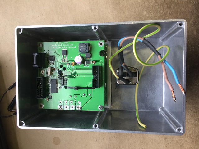 Metcal clone
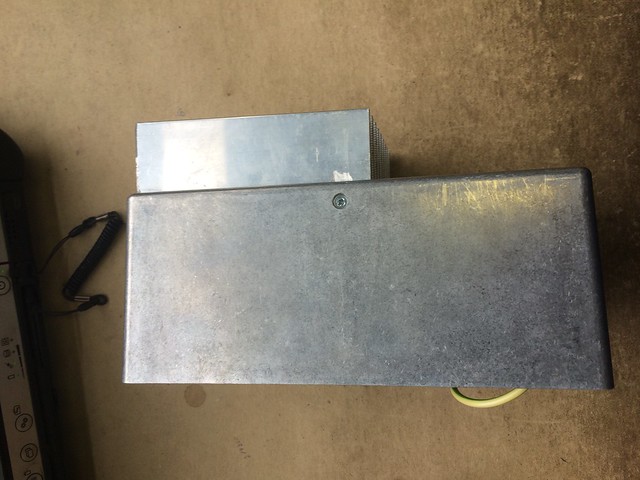 Metcal clone
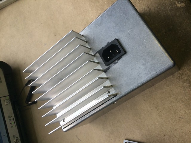 Metcal clone
 Metcal clone