-
Here's another question, for the power supply portion of the circuit I can go two ways:
1) Use one of those cute PCB mount, encased toroidal transformers (Talema and Acme are common brands). I'd have wire to board terminal blocks to bring in the AC (obviously I'd have connections for both primaries to wire it up for 120/240V).
2) BYOT: Bring your own transformer. I'd have a terminal block to accept the output of a center tapped 18V-18V transformer that would be located off-board. The diode bridge and regulators would be located on-board, of course. You could also power the board from a DC lab supply this way as well.
Chassis mount transformers are readily available if you don't have one on hand, so I'm inclined to go with option 2 (I wouldn't have to deal with creepage/clearance, fusing, etc. and it *would* save a lot of space; a 15VA PCB mount transformer is about 60x60mm).
That said, I *can* do the first option if you guys really want a complete self contained package.
-
I think a case mount transformer is a better idea.
That the PCB does not contain any dangerous voltages so you can poke around it as much as you want. Also means you can use a transformer that might be laying around or even feed it from a DC supply since the rectifiers are just going to pass it straight trough. -
My perspective, which is as a demo unit for kids and non electronics people.
I would like it to be as visually pleasing and as old school as possible, with aesthetics as a design constraint, though I don't feel like dead bugging it.
I will put a perspex lid on the top of it. Even the odd gimmicky LED within the case to show it off.
I can understand if you can't cater for this though.
-
GK: Wow, nice project!
 I saw this a few days ago but it took me a while to get around to logging in.
I love the old-school analog design and it was nice to go over your schematics and be reminded of BJT circuits that I'd mostly forgotten.
Also, it's so nice to see someone jumping in to design a PCB for for this project, and everyone else helping out. I love seeing a group excited about a project. Can't wait to see how it turns out.
I tempted to build one myself, but I'm so enamored of the dead-bug aesthetic as GK presented it, that I'd probably go that route. -
Here's another question, for the power supply portion of the circuit I can go two ways:
1) Use one of those cute PCB mount, encased toroidal transformers (Talema and Acme are common brands). I'd have wire to board terminal blocks to bring in the AC (obviously I'd have connections for both primaries to wire it up for 120/240V).
2) BYOT: Bring your own transformer. I'd have a terminal block to accept the output of a center tapped 18V-18V transformer that would be located off-board. The diode bridge and regulators would be located on-board, of course. You could also power the board from a DC lab supply this way as well.
Chassis mount transformers are readily available if you don't have one on hand, so I'm inclined to go with option 2 (I wouldn't have to deal with creepage/clearance, fusing, etc. and it *would* save a lot of space; a 15VA PCB mount transformer is about 60x60mm).
That said, I *can* do the first option if you guys really want a complete self contained package.
Use #2, I would not trust high voltage mains on home etched PCBs due to possible poor etching leaving a conductive path for the mains & I fear, for some, I would rather see them use an approved AC out wallwart keeping them away from any exposed mains. Others who know or are capable will just wire their own transformer, just make sure there is enough heat-sinking & power filtering caps to deal with an AC transformer between 15v and 18.6v.
+, this solution allows for a dual lab power supply set to +/-18v to power this project as well.
-
2) Use horizontal trimmers and locate them near the edge.
You cannot predict the type of chassis the user may be placing their PCB in. Look at GK's metal frame with the front panel. If you place a horizontal trimmer there, the user would need to remove his PCB to adjust that trimmer. Some chassis may have walls around all 4 sides, meaning, anytime a trimmer needs adjusting, they will need to remove their PCB from it's chassis, while functioning. For this project, it is best to have all trimmers top vertical adjustable no matter what. As aforementioned, this may be made and assembled by students and we want to keep thing safe and easy access to probe and play.
Hmm, hadn't thought about that. Fair enough! I'll use vertical ones and just put holes in the top PCB then.
-
Here's another question, for the power supply portion of the circuit I can go two ways:
1) Use one of those cute PCB mount, encased toroidal transformers (Talema and Acme are common brands). I'd have wire to board terminal blocks to bring in the AC (obviously I'd have connections for both primaries to wire it up for 120/240V).
2) BYOT: Bring your own transformer. I'd have a terminal block to accept the output of a center tapped 18V-18V transformer that would be located off-board. The diode bridge and regulators would be located on-board, of course. You could also power the board from a DC lab supply this way as well.
Chassis mount transformers are readily available if you don't have one on hand, so I'm inclined to go with option 2 (I wouldn't have to deal with creepage/clearance, fusing, etc. and it *would* save a lot of space; a 15VA PCB mount transformer is about 60x60mm).
That said, I *can* do the first option if you guys really want a complete self contained package.
Use #2, I would not trust high voltage mains on home etched PCBs due to possible poor etching leaving a conductive path for the mains & I fear, for some, I would rather see them use an approved AC out wallwart keeping them away from any exposed mains. Others who know or are capable will just wire their own transformer, just make sure there is enough heat-sinking & power filtering caps to deal with an AC transformer between 15v and 18.6v.
+, this solution allows for a dual lab power supply set to +/-18v to power this project as well.
Yeah, that was my thought as well. Option #2 it is!
The power supply is also the only part of GK's circuit I've considered changing. I was thinking about using an LM317/LM337 (or 7815/7915) type setup instead of the discrete circuit GK shows, for a couple of reasons: Better regulation, short circuit proof, better SOA, thermal shutdown and better dropout. It would also be a lot more compact, not requiring the large TO-2 transistors of GK's design.
Of course it wouldn't be totally discrete like his design, but it's still close to era appropriate. It would also be a lot more robust for people experimenting with the circuit (I know I hate chasing down power supply issues when I'd rather be experimenting).
Again, it's up to you guys.
-
I'd say stick with GK's regulators.
Then it's all discrete transistor level (no ICs). -
All top-oriented trimmers would be ideal. However, I'd be fine with a small number of trimmers on the side, preferably all on one side, so I'd only have to make access holes on one side of an enclosure (e.g., the rear panel). Assuming that heat isn't an issue, I'd even be OK with mounting the bottom board upside-down so that I could trim it from the top and bottom of an enclosure (i.e., stand it on its side with top and bottom covers removed for access to trimmers on both boards).
Regarding the power supply, having it separate makes sense for many reasons. For my own use case, I'd probably run it from a bi-polar DC lab supply given that I wouldn't be playing it often enough to justify building/dedicating a supply for it.
Speaking of enclosures, I saw the other day an Instek CRO that was mostly empty inside. Everything except the power supply and front panel electronics was on a single PCB on the bottom. The power supply was on top with lots of vacant space. One could just install this Pong project inside the scope. Then, add a switch for Scope or Pong mode.
-
I'd say stick with GK's regulators.
Then it's all discrete transistor level (no ICs).
+1 from me.
Beside, the builder, I assumed none are totally noob with zero experience say in electronics, and remember, an oscilloscope is mandatory.
Vote for originality, as this is becoming a fun/nostalgic/aesthetic project rather than pure electronic project anymore, imho. -
I'd say stick with GK's regulators.
Then it's all discrete transistor level (no ICs).
+1 from me.
Beside, the builder, I assumed none are totally noob with zero experience say in electronics, and remember, an oscilloscope is mandatory.
Vote for originality, as this is becoming a fun/nostalgic/aesthetic project rather than pure electronic project anymore, imho.
That's cool. I actually have a design I've used in the past for a fully discrete linear regulator that uses only three transistors, is short circuit proof and implements current limiting.
The design is actually built upon the simple pass regulator GK used, so with some clever layout, I can actually make it so the builder can implement either design. If you want a current limit, improved regulation and short circuit protection, just add two more small transistors, a couple of resistors plus a cap and you're set. If not, just populate the four components of the original design and solder a jumper down.
And both options are still 100% discrete. (FYI, that's the only part of the circuit I'm modifying. I've been burned quite a few times in the past by shorting part of a circuit out while probing, which leads to vaporized traces and damaged parts. All it takes is a slip of the springy ground tip on the scope probe to short something out, or a component placed backwards. The current limit on your lab supply doesn't help here, since the input filter caps of the local supply still hold significant energy.)
Hopefully this is an acceptable compromise to everyone.
-
That's cool. I actually have a design I've used in the past for a fully discrete linear regulator that uses only three transistors, is short circuit proof and implements current limiting.
The design is actually built upon the simple pass regulator GK used, so with some clever layout, I can actually make it so the builder can implement either design. If you want a current limit, improved regulation and short circuit protection, just add two more small transistors, a couple of resistors plus a cap and you're set. If not, just populate the four components of the original design and solder a jumper down.
And both options are still 100% discrete. (FYI, that's the only part of the circuit I'm modifying. I've been burned quite a few times in the past by shorting part of a circuit out while probing, which leads to vaporized traces and damaged parts. All it takes is a slip of the springy ground tip on the scope probe to short something out, or a component placed backwards. The current limit on your lab supply doesn't help here, since the input filter caps of the local supply still hold significant energy.)
Hopefully this is an acceptable compromise to everyone.
That sounds really great!
I wanted it to remain all discrete (no ICs), so that it **Could** have been made in the 1950s/1960s etc, in principle. Authentic vintage retro (or whatever the terminology is suppose to be).
I like the idea of having the extra pair of transistors (optionally). As current limits are useful. E.g. With so many transistors/components to insert/solder, you can accidentally have a shorting solder bridge go unnoticed or have one or two components put in the wrong way round etc etc. So it would minimize the damage.
I understand your temptation to just put in LM317's. But by having it all discrete, it makes it that much more fun.
E.g. Some people make large 555 timer **IC's**, out of discrete transistors (there are kits available), just for fun! -
That's cool. I actually have a design I've used in the past for a fully discrete linear regulator that uses only three transistors, is short circuit proof and implements current limiting.
The design is actually built upon the simple pass regulator GK used, so with some clever layout, I can actually make it so the builder can implement either design. If you want a current limit, improved regulation and short circuit protection, just add two more small transistors, a couple of resistors plus a cap and you're set. If not, just populate the four components of the original design and solder a jumper down.
And both options are still 100% discrete. (FYI, that's the only part of the circuit I'm modifying. I've been burned quite a few times in the past by shorting part of a circuit out while probing, which leads to vaporized traces and damaged parts. All it takes is a slip of the springy ground tip on the scope probe to short something out, or a component placed backwards. The current limit on your lab supply doesn't help here, since the input filter caps of the local supply still hold significant energy.)
Hopefully this is an acceptable compromise to everyone.
That sounds really great!
I wanted it to remain all discrete (no ICs), so that it **Could** have been made in the 1950s/1960s etc, in principle. Authentic vintage retro (or whatever the terminology is suppose to be).
I like the idea of having the extra pair of transistors (optionally). As current limits are useful. E.g. With so many transistors/components to insert/solder, you can accidentally have a shorting solder bridge go unnoticed or have one or two components put in the wrong way round etc etc. So it would minimize the damage.
I understand your temptation to just put in LM317's. But by having it all discrete, it makes it that much more fun.
E.g. Some people make large 555 timer **IC's**, out of discrete transistors (there are kits available), just for fun!
Yeah, I've got one of the discrete 555 timer kits I picked up at Bay Area Maker Faire in 2014. I even made a little adapter lead that's wired into the board and terminates into an 8-pin DIP footprint, letting you plug the giant discrete board into any circuit that uses a normal DIP 555. It's a great teaching aid to help explain the 555 and let people probe the internals in working circuits, and when not in use makes a good conversation piece! -
Yeah, I've got one of the discrete 555 timer kits I picked up at Bay Area Maker Faire in 2014. I even made a little adapter lead that's wired into the board and terminates into an 8-pin DIP footprint, letting you plug the giant discrete board into any circuit that uses a normal DIP 555. It's a great teaching aid to help explain the 555 and let people probe the internals in working circuits, and when not in use makes a good conversation piece!
I was tempted to get one of those too but haven't yet. There's a discrete 741 too which looks interesting.
I think a discrete 78xx regulator in the same style would be cool too, maybe some other classic ICs. -
Yeah, I've got one of the discrete 555 timer kits I picked up at Bay Area Maker Faire in 2014. I even made a little adapter lead that's wired into the board and terminates into an 8-pin DIP footprint, letting you plug the giant discrete board into any circuit that uses a normal DIP 555. It's a great teaching aid to help explain the 555 and let people probe the internals in working circuits, and when not in use makes a good conversation piece!
I was tempted to get one of those too but haven't yet. There's a discrete 741 too which looks interesting.
I think a discrete 78xx regulator in the same style would be cool too, maybe some other classic ICs.
I've been meaning to get the discrete 741. I'll order it one of these days.
I've also been thinking about making a discrete 317 kit. They're pretty complex internally, so it would take some work to translate from the datasheet schematic to a real, working discrete circuit (node capacitance, trace and lead inductance/resistance plus the varying parameters of discrete transistors all have to be taken into account). Still, it would be a fun project!
A tiny TL431 kit would be cool to make as well (they're actually fairly simple and schematics are available in the datasheet). Basically it's just a couple of transistors in an op-amp configuration, a shunt voltage reference and a driver transistor on the output. It's just a matter of figuring out the hfe ratios between some of the transistors and picking the correct parts. That can be done with basic math, plus a bit of trial and error during simulation.
I've really been enjoying putting together this Scope Pong kit, so maybe I'll do a TL431 next, then a 317.
Speaking of which, I should have the Pong schematics done tonight. I'll post them here, along with a single PDF containing all of GK's schematics, for review. That way I get a few eyeballs telling me if I've missed anything.
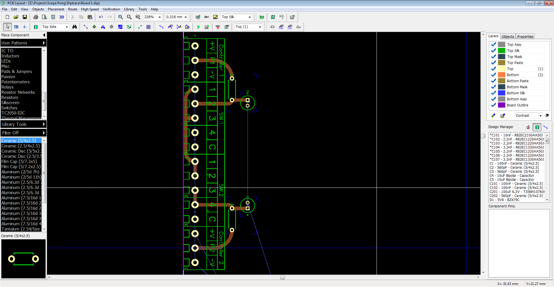
It's taken me a bit longer than I anticipated to get the schematics finished, but my parts library in Diptrace wasn't setup for through hole, so I had to add a lot of parts. Generally I never use the Diptrace supplied library, even though it is reasonably well stocked; I have my own naming scheme for stuff and in the case of these TH parts, I wanted different pad spacing than they provided (like the 7.62 spacing for the 1/4w resistors). -
Oh yeah, one more question for you guys: The controllers!
So the only part that actually needs to be in the controller enclosure is the 5K pot, so you won't need a board or anything for it. You can just get a small handheld plastic case from Hammond or wherever, drill a hole in the middle and install a chassis mount pot. The P1 controller will also have a push button on it for serving the ball, but again this can all be free wired right from the cable.
Now, I was looking through Digi-Key for a suitable connector to use on the Pong box and I found a good option. It's a 6-pin mini-DIN connector. They're less than a dollar and have like 15,000 in stock. There's also a mating male connector (solder cup type) available, complete with strain relief.
Now, the connector I've currently specced is PCB mount, which I figure would work out for most people. It'll be mounted on the front of the board, so if you make a custom case you can just drill a hole in the correct position. And, because of the length of the housing on male mini-DIN connectors, the board doesn't even have to be flush against the back of the front panel; think of the AT keyboard connector and how it wasn't flush against the case of old PCs.
Now, I know this may not be acceptable for some of you, because of whatever enclosure you're planning. That's alright, as Digi-Key *also* has a panel mount 6-pin mini-DIN connector available. In that case, you could just use that and solder wires between the terminals and the TH pads on the board. (Or you could use a D-sub connector, or hardwire the controllers in, whatever you want.)
For the DP4T switch, I've currently just put down labeled TH pads, so you can wire up a panel mount rotary switch.
I've made sure the TH pads on both the connector *and* switch footprints are large enough for 22AWG wire and the rings are wide enough for easy soldering.
Hopefully this will workout for those who plan to build custom cases and those who don't want to use a case.
-
I've made sure the TH pads on both the connector *and* switch footprints are large enough for 22AWG wire and the rings are wide enough for easy soldering.
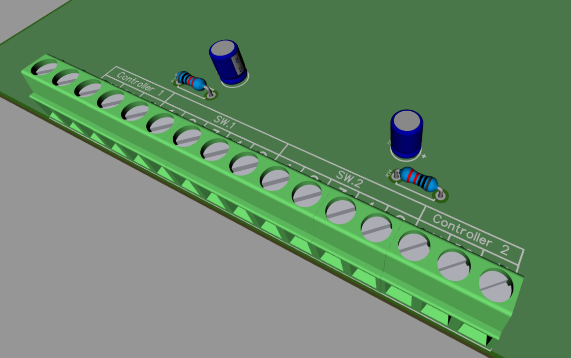
Choose a cheap standard terminal strip as a component for these. This way, the user can either soldier the wires directly, or, purchase cheap terminal blocks to have the ability to screw on and off the wires.
Go with these. I know they are large, but, this means the pad holes on the PCB you make will also be large to soldier wires directly with clearance & these terminals are also strong enough for the AC power input as well.
For 7.5mm pitch: (Recommended so that there is room for bare wires to be soldered directly on the PCB if you dont want to buy)
https://www.digikey.com/products/en/connectors-interconnects/terminal-blocks-wire-to-board/371?k=ED365
Or, for 3.5mm pitch:
https://www.digikey.com/products/en/connectors-interconnects/terminal-blocks-wire-to-board/371?k=ed555
-
I've made sure the TH pads on both the connector *and* switch footprints are large enough for 22AWG wire and the rings are wide enough for easy soldering.
Choose a cheap standard terminal strip as a component for these. This way, the user can either soldier the wires directly, or, purchase cheap terminal blocks to have the ability to screw on and off the wires.
Go with these. I know they are large, but, this means the pad holes on the PCB you make will also be large to soldier wires directly with clearance & these terminals are also strong enough for the AC power input as well.
For 7.5mm pitch:
https://www.digikey.com/products/en/connectors-interconnects/terminal-blocks-wire-to-board/371?k=ED365
Or, for 3.5mm pitch:
https://www.digikey.com/products/en/connectors-interconnects/terminal-blocks-wire-to-board/371?k=ed555
Not a bad idea. I could put footprints down for the 3.5mm versions. I've already got the 5mm versions specced in for the input from the transformer. (I went large there so there was wide area for the GND pour to connect to.) -
Stick with 1 size for all. 5mm should be easy to work with and you got room for a quality trace inbetween.
3.5mm will be a little tight for hand soldiering wires if someone decides not to use terminal blocks to save the few $$$.
-
Stick with 1 size for all. 5mm should be easy to work with and you got room for a quality trace inbetween.
3.5mm will be a little tight for hand soldiering wires if someone decides not to use terminal blocks to save the few $$$.
Yeah, I think you're right. I added 5mm ones last night and they look like they'll work just fine.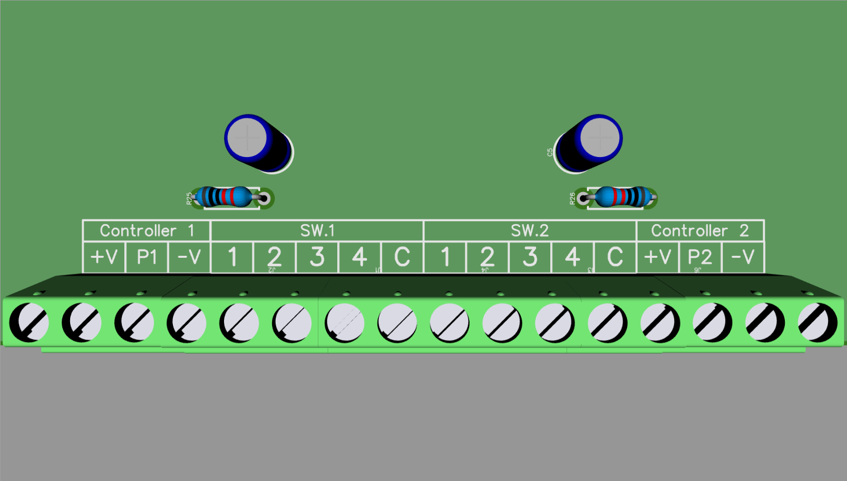
-
Nice terminal blocks. Once I used high quality Phoenix Contact blocks for a project, with press-fit technology, which doesn't need soldering. Now they have even simpler connectors, didn't know this SKEDD technology:
But I guess they are expensive, and they look too modern But you need to connect it only once for this project, so for me just soldering wires to the board would be ok.
Yeah, the pads should be large enough to just solder wires right into it, if that's the way you want to go.
Those SKEDD blocks look pretty cool, expensive though!
So, I've only got one more schematic to capture tonight, the Horizontal and Vertical Deflection Circuit. I'll post the PDF in a bit for review. -
The quality of construction used here (which is very high) reminded me of something and it's taken me a while to find it. Have a look at this:
http://techno-logic-art.com/clock.htm
It seems that this style of construction has quite a following:
http://techno-logic-art.com/images4/fc7_2.jpg
-
Okay guys, here's the completed schematics:
http://timb.us/PDF/Scope_Pong_20170326.pdf
Have a review, let me know if you see any errors.
Edit: Crap, I uploaded a slightly older version by mistake. That's missing the Multiplexer Logic, Deflection and Collision schematics. Everything else is finished in that schematic, so you can still have a look through it. I'll upload the complete version later today when I get back to my laptop.