-
It's made The Register too:
https://www.theregister.co.uk/2017/04/05/oscilloscope_pong/
Congrats, GK! -
It's made The Register too:
https://www.theregister.co.uk/2017/04/05/oscilloscope_pong/
Wow!
With all this interest, it makes me wonder how many kits one could sell for this ?
(Being practical it would be very limited, as how many people have access to a suitable scope, too few I imagine). -
It's also a non-trivial amount of soldering. But, hey, you don't have to build it all in a single weekend.
-
It's also a non-trivial amount of soldering. But, hey, you don't have to build it all in a single weekend.
In the 1970's, when Pong (Electronic TV Table tennis) projects?/Kits?/Designs? (I'm not sure of the exact source, but it was probably electronics magazines) were popular, some electronics hobbyists/enthusiasts would build their own, out of something like a 100 or hundreds of TTL/CMOS? (probably TTL) integrated circuits. Not a microprocessor or complex IC in sight.
The PCB's were huge, like two feet square (from memory).
They were great fun to play at the time.
Later I think there were single IC versions available, and later still ones with switchable multiple games, built in. Such as Football/Squash etc. Eventually tank attack games, if I remember correctly, and colour versions.
I hear/believe these days, all the transistors need to be pre-soldered apart from one transistor, one resistor and nothing else as the attention span would be exceeded. Then they built it all themselves
-
I'd use this project as a measure of how good a digital scope in X/Y mode can emulate a real analog scope.It's made The Register too:
https://www.theregister.co.uk/2017/04/05/oscilloscope_pong/
Wow!
With all this interest, it makes me wonder how many kits one could sell for this ?
(Being practical it would be very limited, as how many people have access to a suitable scope, too few I imagine).
Basically it will be one of my test bench marks when purchasing my next digital scope. -
Okay, so here's what I came up with:
Perfect.
http://timb.us/PDF/Scope_Pong_XYZ_V3.pdf
I shifted the diodes around a bit to save space, but I still kept it very compact and the lines running to the drain nodes of the JFETs are each around 20mm. I still need to place the trimmers (ignore them in the image), but so far so good I think.
-
I'd use this project as a measure of how good a digital scope in X/Y mode can emulate a real analog scope.It's made The Register too:
https://www.theregister.co.uk/2017/04/05/oscilloscope_pong/
Wow!
With all this interest, it makes me wonder how many kits one could sell for this ?
(Being practical it would be very limited, as how many people have access to a suitable scope, too few I imagine).
Basically it will be one of my test bench marks when purchasing my next digital scope.
Probably cheaper to just own multiple scopes
-
Yeah, I'll have to fix the focus on my old CRO for this.

-
Digital scopes do vary somewhat in their X/Y behaviour. Not all have Z inputs. The RTB2004 has, AFAIK uniquely, an XYY mode, which will show two XY traces in different colours. It may be that there are a few true dual-gun CRT scopes that can do this ( obviously not in different colours) .
I'd use this project as a measure of how good a digital scope in X/Y mode can emulate a real analog scope.It's made The Register too:
https://www.theregister.co.uk/2017/04/05/oscilloscope_pong/
Wow!
With all this interest, it makes me wonder how many kits one could sell for this ?
(Being practical it would be very limited, as how many people have access to a suitable scope, too few I imagine).
Basically it will be one of my test bench marks when purchasing my next digital scope.
If the output bandwidth is within the audio range, it would be useful to record the output to a WAV file so people can test on different scopes.
-
Okay, so here's what I came up with:
Perfect.
http://timb.us/PDF/Scope_Pong_XYZ_V3.pdf
I shifted the diodes around a bit to save space, but I still kept it very compact and the lines running to the drain nodes of the JFETs are each around 20mm. I still need to place the trimmers (ignore them in the image), but so far so good I think.
I also fixed the Z-Select header pads since that PDF. Hole size is 1.1 and pad size is 2.2. -
Digital scopes do vary somewhat in their X/Y behaviour. Not all have Z inputs. The RTB2004 has, AFAIK uniquely, an XYY mode, which will show two XY traces in different colours. It may be that there are a few true dual-gun CRT scopes that can do this ( obviously not in different colours) .
Hmmm, a 192khz 16bit stereo sample. Unfortunately, DC coupling will be lost, but, maybe with a flat down to 1Hz system, you can still generate a valid test sample. Probably saving it in a FLAC format will super compress it because of the repeating nature of the signal. Any other lossy audio format would make a mess of things.
If the output bandwidth is within the audio range, it would be useful to record the output to a WAV file so people can test on different scopes.
-
For testing how good a digital scope might display it, you could use the YouScope demo:
It looks quite good on a million waveforms per second update Agilent scope with some persistence tricks to remove the flyback traces, as Dave shows in the video, but really crap on less good digital scopes. Lossless FLAC file: http://kapsi.fi/~jpa/stuff/other/youscope-wave.flac
With the z-signal the Agilent scope might be really good for the pong game. -
Very hard to predict demand for something like this but my guess is "more than you'd think".
A kit might be a candidate for Tindie or Crowdsupply, maybe even Kickstarter.
But one issue is you don't want to be saddled with supporting people who can't solder.
It would be nice to be able to leverage the savings from buying PCBs and parts in quantity, especially if you could find a supplier to kit up the parts.
Speaking of supply etc., has any effort yet been put into BOM minmisation?
One other comment re. ease of assembly - it would be nice if all diodes withing a local group were the same way round - a bit if a fiddle for PCB layout but could reduce risk of errors quite a bit. Ditto polarised caps.
-
Organizing the kits, shipping, customer communication etc. is always a lot of work in my experience with my C64 Kerberos cartridge. The easiest way might be to contact a manufacturer like Evil Mad Scientist, who sell the 555 kit:
http://shop.evilmadscientist.com/productsmenu/652
and ask them, if they want to sell a pong kit. Then you can sell them the PCB layout for a good one time price. Maybe less profit than when you do it yourself, but no risk and no tedious manufacturing and shipping work, but still everyone can buy the kit.
If you want to sell it yourself, iteadstudio has an assembly service, for fully populated boards, which some people might prefer:
http://support.iteadstudio.com/support/solutions/folders/1000212715
They say up to 25 boards, but maybe they can help you find a cheap service for larger quantities as well. Their boards are very good and cheap, so I guess their assembly service has the same quality. Maybe get a quote from them for 25 of your boards, then create a Kickstarter project with minimum funding required to pay the 25 boards (with a good factor like 3x for all the work etc.), no risk. Judging by the media echo, it should be no problem to sell 25 boards. And of course, some people, like me, would like to buy a kit, so this should be another Kickstarter reward. -
Organizing the kits, shipping, customer communication etc. is always a lot of work in my experience with my C64 Kerberos cartridge. The easiest way might be to contact a manufacturer like Evil Mad Scientist, who sell the 555 kit:
http://shop.evilmadscientist.com/productsmenu/652
and ask them, if they want to sell a pong kit. Then you can sell them the PCB layout for a good one time price. Maybe less profit than when you do it yourself, but no risk and no tedious manufacturing and shipping work, but still everyone can buy the kit.
If you want to sell it yourself, iteadstudio has an assembly service, for fully populated boards, which some people might prefer:
http://support.iteadstudio.com/support/solutions/folders/1000212715
They say up to 25 boards, but maybe they can help you find a cheap service for larger quantities as well. Their boards are very good and cheap, so I guess their assembly service has the same quality. Maybe get a quote from them for 25 of your boards, then create a Kickstarter project with minimum funding required to pay the 25 boards (with a good factor like 3x for all the work etc.), no risk. Judging by the media echo, it should be no problem to sell 25 boards. And of course, some people, like me, would like to buy a kit, so this should be another Kickstarter reward.
It's an interesting thought, but I think we should see how the initial kits do here first. If there's more interest outside of the forums it'll totally be up to GK if he's OK with it being sold in some commercial fashion or not. (I only got GK's blessing to produce and sell a run of kits and/or boards to forum members.) Now, if it did turn out to be amazingly popular and there was a ton of demand outside the forum, I'd be more than happy to work out something so he gets paid royalties on any kit sales or something, but like I said, it's up to him where this goes and if it gets sold outside the forum at all.
As for assembled versions, it would be pretty expensive to have them assembled, due to it being all through hole, combined with the size of the boards. Most assembly houses (at least the ones I know of here in the US and China) don't have equipment for automated insertion of Th parts, and if they do it's only for large runs. Instead, they have people manually stuff the boards, which is fine when you're dealing with one or two TH parts on an otherwise SMD board, but not over 700!
Now, all the parts are available in surface mount variations, which would allow automated assembly *and* would cut the board size down by 2/3. That said, I don't see the point myself. I mean, half the fun in something like this is actually soldering the thing, plus the whole retro look and feel!
At any rate, like I said earlier, let's see how the basic kit does here, first.
-
Tonight I got the power supply section done:
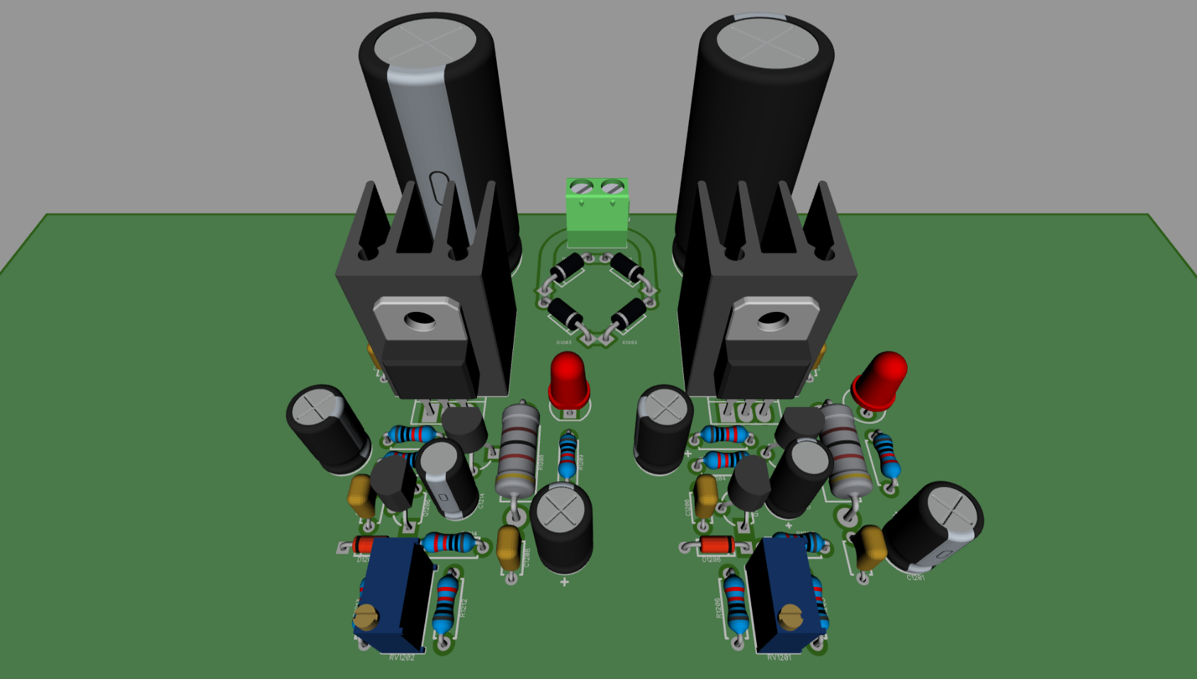
http://timb.us/PDF/Scope_Pong_Power.pdf
Each +15V and -15V rail sub-section (that includes the TO-220 Darlington, heatsink, Zener, support passives, adjustment pot and two 2N390x transistors) takes up only slightly more space than a *single* TO-3 transistor, so it's basically the same size (board wise) as GK's original circuit. My circuit includes improved regulation, adjustable output voltage (the adjust pot can be jumpered and the top fixed value resistor increased to ~12K if adjustment is not needed), improved regulation (about 50mV over line and load) and lower ripped (less than 5mV at full load, 500uV at 1/4 load).
It'll do 500mA easily and has a current limit of 800mA. I wanted to make sure it could do the added current to handle a potential scoring add-on board someone may make.
I've used a similar circuit on another board in the past and it works great. I've also tested this exact circuit and it seems to work perfectly. It's not *that* much more complex than the original power supply, but provides some nice benefits. If you guys don't like it, I can always make the power board modular and provide two options, one for the original TO-3 design and one for mine.
Here's the updated schematic:
http://timb.us/PDF/Scope_Pong_20170406.pdf
Edit: Fixed link to schematic. -
For something this niche I don't think it would be worth offering more than two things - PCB only, and full kit.
As soon as you start looking at assembly, there's a much bigger committment and work needed.
Even a SMD version would be fairly expensive to assemble due to the high component count, and SMD would probably detract from some of the retro-ness.
I'd say it would definitely be worth talking to EMSL - they are nice people - they may or may not be interested in carrying it themselves, but may at least have some useful advice.
If you do want to persue it as a product I definitely think it would be good to somehow get it on display at Bay Area Maker Faire.
-
Tonight I got the power supply section done:
Would be worth making sure there's space to mount the caps horizontally , and have holes for securing wires/cableties as these will be the tallest parts.( Maybe also the voltage regs?)
I'd also suggest you include a polyfuse on the input for safety.
Maybe also a PCB-mounted on/off switch.
Ah yes, good idea on horizontal area for the caps. These are 16x32.5mm (7.5mm lead spacing) caps, so it'll use quite a bit of space to do them horizontal, but where I plan on placing this section there should be room. I'll squeeze in space for cable tie holes.
Originally I was actually going to put in a polyfuse, but couldn't decide on if it was really needed or not. I don't suppose there would be any issue placing it on the AC side of the rectifier? (It just occurs to me I've never seen them rated in anything but VDC, but I can't think of any reason why it wouldn't work, so long as the rating is above the peak AC voltage.)
I figured the user would route either the 120/240VAC through a panel mount switch before going into the transformer, though I could add a DPST switch between the terminal block and rectifier for good measure. (The user can always jumper it if they don't need it I guess.) -
Originally I was actually going to put in a polyfuse, but couldn't decide on if it was really needed or not. I don't suppose there would be any issue placing it on the AC side of the rectifier? (It just occurs to me I've never seen them rated in anything but VDC, but I can't think of any reason why it wouldn't work, so long as the rating is above the peak AC voltage.)
I think it is important, as someone may use a big-ass transformer they just happen to have available, which could make a lot of smoke.
BTW you appear to have forgotten a centre-tap connection for the transformer. Obviously you need 2 PFs.
May also be worth adding a footprint (connector or links) for DC-in, in case someone already has a suitable supply.Quote
I'm thinking if someone has an already-cased transformer, it may be convenient to have a local switch.
I figured the user would route either the 120/240VAC through a panel mount switch before going into the transformer, though I could add a DPST switch between the terminal block and rectifier for good measure. (The user can always jumper it if they don't need it I guess.)
220R for a red LED on 15v is way too low. Should be more like 1K
-
Hmmm, those little TO-220 heatsinks probably have a thermal resistance in the vicinity of 25-30 deg.C/W. The positive rail one will be sweltering at around 80 deg.C at a minimum at room temp. given the current consumption of the positive rail, not counting the possible additional drain of an add-on scoring unit. 800mA will melt some silicon.
15VAC rather than 18VAC input will give you enough regulator headroom with adequate filtering after rectification, and about half the power dissipation.
The trimmer potentiometers for adjusting the regulator output voltages should be shifted to the feedback resistor leg between the control transistors base and ground. That way if the trimmers wiper goes open circuit the rail voltage will collapse to around 7V, rather than go in the opposite direction and saturate close to the unregulated input potential.
Those heatsinks are surprisingly good, much better than the crappy stamped metal ones you normally see. I tested it pulling about 300mA and case temperature got up to about 70c, that's with a 18VDC input.
Edit: These heatsinks have solder pins, so I've got them hooked to the ground plane to increase thermal dissipation.
An 18Vct transformer is the maximum I would recommend, but it would work best with a 15Vct transformer, yes. (In fact, on the layout PDF that should have said "18-0-18 Max Input, 15-0-15 Min Input" but I forgot to change it.
Current limit can be lowered by simply increasing the 1ohm resistor to 1.5 or 2 ohms. Though, the idea is to more or less prevent a dead short from immediately blowing the power transistor, rather than protecting it during a sustained fault. I may have a simple method of implementing snap back current limiting, but I'm not sure it's worth it overall.
Good catch on the trimmer; that's the way I originally had it wired up on the breadboard.I think it is important, as someone may use a big-ass transformer they just happen to have available, which could make a lot of smoke.
BTW you appear to have forgotten a centre-tap connection for the transformer. Obviously you need 2 PFs.
May also be worth adding a footprint (connector or links) for DC-in, in case someone already has a suitable supply.
Okay, Polyfuse it is. Good catch on the center tap! I can't believe I forgot that... I'll switch the connector over to a 3-way.
I figured the user could just push +-18VDC in through the regular AC input, but if you think it would be worthwhile, I'll make provisions. -
Okay, Polyfuse it is.
I would like to have good old glass fuses. With fuse holders, in case someone blows it up. AC side would be best, then it would trip too if the rectifier shorts.
-
Okay, Polyfuse it is.
I would like to have good old glass fuses. With fuse holders, in case someone blows it up. AC side would be best, then it would trip too if the rectifier shorts.
Keep in mind the user would likely (at least they *should*) already have a chassis mount fuse holder installed on the mains side of the transformer. (That protects you in case of a transformer short as well.)
I thought of putting down a glass fuse on the board as well, post transformer, but can't think of any advantages compared to a polyfuse. (They take up a lot of space too.)
I'm thinking, if someone really wanted a glass fuse on the low voltage side of the transformer they could always just use a chassis mount one. However, if you guys would really prefer that over a polyfuse, I *can* do it on the board, though I'd rather not.