What happened to the PCB project in this thread?
For whatever reason I presume timb lost interest. If so, perhaps a suggestion to post the unfinished design files (should someone else feel enthusiastic about finishing the project) wouldn't be out of order. Though actual worthwhile collaborative projects that actually come to fruition are nearly as rare as rocking horse poo on these forums anyway. A general waste of time really.
For whatever reason I presume timb lost interest. If so, perhaps a suggestion to post the unfinished design files (should someone else feel enthusiastic about finishing the project) wouldn't be out of order. Though actual worthwhile collaborative projects that actually come to fruition are nearly as rare as rocking horse poo on these forums anyway. A general waste of time really.
I wish he did the work in Protel99SE.... I would be glad to finish the project as I have the free time in multitudes.
(Though I only have a digital scope, it still has XY, but not blanking. I can get one one of my old analog ones back from an old friend I gave it to for temporary play...)
For whatever reason I presume timb lost interest. If so, perhaps a suggestion to post the unfinished design files (should someone else feel enthusiastic about finishing the project) wouldn't be out of order. Though actual worthwhile collaborative projects that actually come to fruition are nearly as rare as rocking horse poo on these forums anyway. A general waste of time really.
timb is still active here, profile says last time seen was yesterday.
BTW, I was thinking of building a version with a microcontroller and a DAC. Would be interesting for something like Maker Faire to show the improvement of technology. Like 60 years ago you needed all these 10 PCBs and now you can do it in one microcontroller with the size of a thumbnail. But might end up as another of my many unfinished ideas and projects

Sorry guys, I didn’t lose interest, work just kept cropping up every time I started back up on it, then I was really sick for nearly two months (which is why I stopped posting here for awhile).
Anyway, I actually started working on the board a over the weekend. It’s literally 90% done, it’s just a matter of cross connecting a few sections together, doing some cleanup and getting you guys to to look at the routing to make sure I haven’t missed anything. After that I’ll send out for a test board and order a set of parts.
Really sorry I didn’t say anything. [emoji20]
How is color pong progressing, GK?
It’s literally 90% done
Great.
90% often means, you just have the other 910% left to do, to finish it off.

Hey, Tim, glad to hear you're doing OK. Being sick for two months is no fun. Welcome back.
I've been preoccupied with other things. Haven't progressed any further with the electronic assembly. However this weekend I got back to it and started the display enclosure. A 3mm-thick sheet of transparent acrylic will be screwed over the top.
I've been preoccupied with other things. Haven't progressed any further with the electronic assembly. However this weekend I got back to it and started the display enclosure. A 3mm-thick sheet of transparent acrylic will be screwed over the top.
Gonna need a bigger pocket!
That's going to look really snazzy, GK. What's the remaining section of copper for?
Ah, of course. Just make some round cutouts in the acrylic top.

Sound effects/synth and the remaining control logic. Might make a start this weekend, but the project is second in priority to finishing off my duck pen.
Quack!

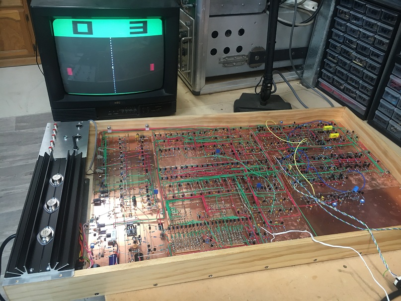
Finally getting stuck into this project again. I have the sound synth circuitry soldered up to the extent that I can play against the machine with the percussive boink ball-bat and ball-boundary sounds. I'm currently waiting on the final batch of parts to arrive in the mail, so I've made some progress on the documentation.
Here is the complete diagram of the colour composite video generation circuitry. Full res. PDF here:
http://www.glensstuff.com/videopong/composite%20video%20generation.pdf
Hello Glen,
a word of thanks for sharing all this with us and for the inspiration! Have a great New Year 2018.
Cheers,
THD+N_bad
Hey thanks.....no worries..... two weeks into the new year gone already.........It feels like I was only just organizing my annual leave last week..
I'm keen to finally get this project off the bench and hanging on the wall. I have the power supply circuitry built and operational now.....


Nice! A compact all discrete transistor portable video pong game console.
That's the plan

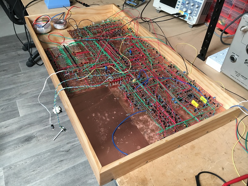
I now have the whole thing operational on its own internal power supply circuitry. Also finally tidied up all of the wiring to the composite colour video signal generator section. Essentially all that I have to build now is the small amount of remaining control logic and the sound effects circuitry which pans the the audio from left to right and vise-versa depending on the horizontal position of the ball. This will all nicely fit into the remaining area of free copper at the end opposite of the big PSU regulator heatsink.
The five RCA sockets in the control panel are to be:
1) Composite video monochrome
2) Audio monaural
3) Composite video colour
4) Audio Left
5) Audio Right


That is a pice of art.

And that it actually does something cool makes it even better.
OK guys, here is a video of this evenings effort. In addition to the previously constructed percussive sound synth circuitry, I now have the stereo panning circuitry operational as well.
I'm feeling lazy so I'll just cut 'n' paste the explanatory text that I posted with the Youtube video:
This project is almost finished now. This video demonstrates the stereo sound panning circuitry, which amplitude-steers the synthesized percussive "boink" sounds (that the ball makes when it hits a paddle or the boundaries) between the left and right audio channels depending on the horizontal position of the ball.
There are no actual sounds operating or recorded in this video though. What I have done, simply for clear demonstration purposes, is to disconnect the sound effects generators and feed a continuous audio-frequency sine wave from a function generator into the stereo panning circuit.
The CH1 (yellow) and CH2 (blue) traces on the oscilloscope screen are the left and right audio channel outputs respectively.
As you can see, when the ball is in the center of the screen, both channel outputs are at equal amplitude, centering the stereo image, but when the ball is rightmost the audio is panned entirely to the right audio channel and vise versa.
So long as you aren't sitting too far away from the screen, the stereo effect is quite convincing, even on a relatively small stereo TV not having by virtue of its size much separation between the left hand and right hand speakers.
Despite having watched this develop, it's still hard to believe you made all that, GK. Amazing and cool.
Very impressive. It would drive me nuts though!
Ha Ha. I wish I was payed to do this 7.5 hrs per day as my day job. Then I'd be able to build something really ambitious
I now have all of the sound circuitry built and operational. The realistic synthesized percussive ball-thwack sounds in addition to the stereo effect really puts this version, audio wise, a level above the original oscilloscope Pong with its simple "computer" beeps.
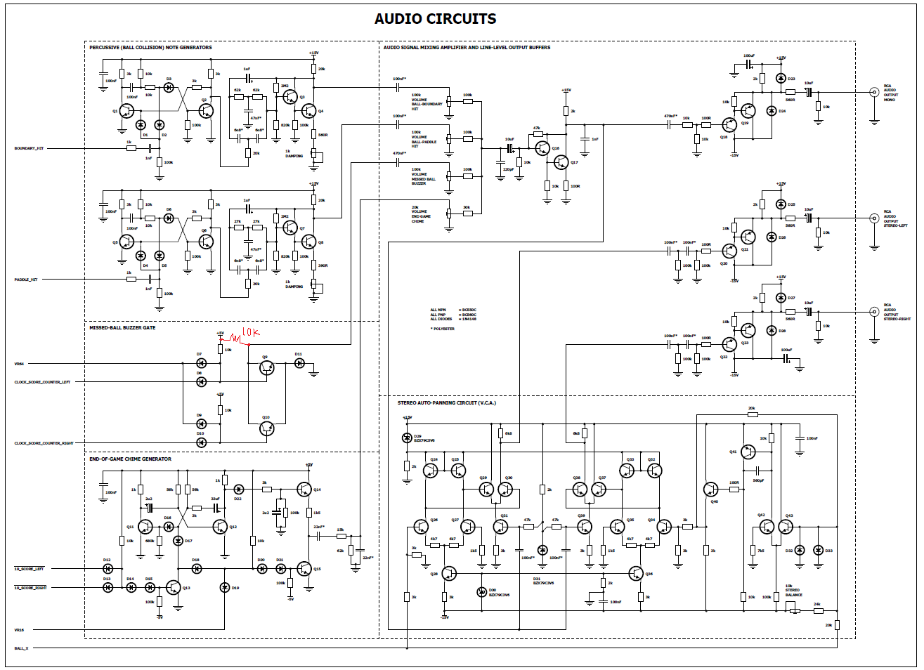
I've just finished drafting the Audio Circuits schematic diagram - preview attached.
It's getting really close now. All that is left to do (besides the rest of the documentation) is to finish off and wire in the remaining the control logic: one player (vs machine) or two player, paddle size selection (large or small), etc.
A tally of the semiconductor count so far (from the currently completed/drafted schematics) is as follows:
Transistors (bipolar) : 431
Transistors (FET) : 6
Diodes : 828
EDIT: Oops - just noticed a missing 10k collector pull-up resistor on the "Missed-ball buzzer gate".
Now when you video demo the final game for Youtube, you'll need to record the audio in stereo...
I picked up a "BD-HDD Combo" recorder unit with composite video and stereo audio inputs this evening which will allow me to do just that.
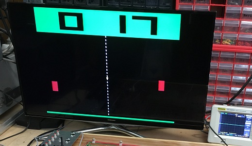
An earlier test on my living room stereo flat screen:
OK, here is where I am with the construction as of this evening. the controls are all wired and I can now select either small or large bat sizes. Now that the remaining paddle control circuitry has been built, in single player mode when the machine takes control of the right hand paddle, the paddle-to-ball offset is now corrected so that the ball hits the center of the paddle (those who watched my previously posted video would have noticed that the ball previously only hit the very top of the machine-controlled paddle.
The bolts that hold the transformers and the earth lug to the mains-stuff sub-chassis do not go through the wooden (12mm-thick ply) base. The wooden base was recessed for the bolt heads underneath the steel plate. This means that if the wooden base ever caught on fire the transformers and the critical earth bond would not work loose from the metal plate. It's all safe.


