-
Actually, he's upset at being connected up to solid state.
-
Actually, he's upset at being connected up to solid state.
BRING ME BILL SHOCKLEY'S HEAD! -
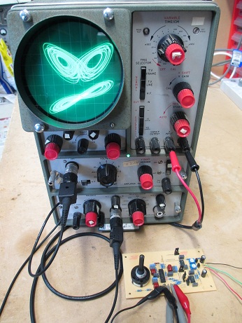
Just got my Lorenz attractor PCB loaded and plugged in, though connected to a more respectable oscilloscope this time. New fangled rubbish like that BWD has no place in a thread like this!

I AM AN ANGRY SCOPE! GET OFF MY FRONT END!
Is this the EE equivalent of a Pumpkin carving contest?
-
Is this the EE equivalent of a Pumpkin carving contest?
Perhaps, but my only formal qualification is as an electronics technician.
Incidentally, the scope is a Telequiptment Type D43. It has a true dual beam CRT, with separate astigmatism, focus and intensity controls for each beam, which is quite unusual. My manual for it is dated 1966 and I got the thing 13 or 14 years ago now. Before now I hadn't plugged it in since then. I was surprised that it still worked 100%. It's still all original inside too. All it really needs is a re-cap and a new green paint job on the chassis, then it will be like new again. The CRT has really nice, bright and sharp traces and one of the plug-in vertical amplifiers has differential inputs and 1mV/div sensitivity. -
Rossler attractor equations are useful in modeling equilibrium in chemical reactions.
They are? (Chemical engineer scratches head...) -
Not sure how equilibrium evolves from chaos, but models for chaotic attractors do seem to be used as analogs in the study of coupled chemical reactions:
http://homes.cs.washington.edu/~seelig/publications/dna_crn_dna14.pdf
-
Interesting paper.
Summarized: the differential equations representing a coupled dynamic system (such as the equations in the first post of this thread) resemble the rate equations that might arise from a coupled system of chemical reactions. In the same manner that such a system may be constructed from analog electronics (this thread), the authors of that paper attempt to construct such a system out of reacting chemical species with appropriate interactions and rate constants. Essentially they want to build an "analog computer" out of chemical reactions that solves the given differential equations and thus behaves in the same manner.
The similarity of such differential equations with the rate equations arising from chemical kinetics did not escape me, but I was being a bit of a pedant in pointing out that dynamic systems are not in equilibrium (when systems are in equilibrium the system variables are static and unchanging). -
I would think that in equilibrium the rate of reaction both ways is the same, but the system is constantly changing one molecule to the other. If one is an irreversable reaction then it will be static, but if you are eg making ammonia it will be static but changing one product to another constantly until you change the conditions when drawing off a portion to change the ammonia gas to a liquid, and the other unused nitrogen and hydrogen reactants are fed back into the reactor vessel.
-
Yes, in an equilibrium system at a microscopic level then molecules may be moving around, but at a macroscopic level anything you can measure (temperature, pressure, concentration) will not be changing with time. Chemical equilibrium reactions are modeled with algebraic equations rather than differential equations. Also it's true that if you disturb the system in some way it will move to a new equilibrium, but as long as you don't touch it it won't change.
-
Same as the scope then, it is an equilibrium around the 2 centres, spending time at each side. Just the chemical reaction is a lot faster and a lot smaller so overall it appears to be static.
-
So are these patterns moving on the scope screen? If so, can someone make a video?
-
After a bit of a hiatus from this chaos stuff, I have finally produced a real-life working electrical analog of Rössler's 4-dimensional, hyperchaotic attractor.
The LTspice files have been add to my (as yet incomplete) webpage: http://www.glensstuff.com/hyperrossler/hyperrossler.htm
Hyperchaos explained here: http://www.scholarpedia.org/article/Hyperchaos
Here is the schematic:
The fourth (w) dimension complicates things a bit. Unlike the 3-dimensional Rössler and Lorenz attractors, the Hyperchaotic Rössler requires appropriate/valid initial conditions to be set and stable prior to being "let go". If this is not done, the complicated control loop will just lock up with the op-amp outputs sitting against the rails. Initial condition forcing is achieved by means of analog switches switching alternate feedback loops to the 4 integrators.
The circuit is also extremely sensitive to both input and output offset error voltages of the analog multiplier. This is due to, mainly, the scaling (down) factor of 40:1 required, to get the solution to fit withing the op-amp and multiplier voltage swing limits. This results in a 40x40 = 1600:1 ratio of scaling between the input levels (b and xz) applied to the z integrator. Hyperchaotic oscillation only happens for limited value ranges of the 4 coefficients. It only takes a very small offset error at the output of the multiplier to force the b coefficient too far out of range to permit a solution.
The circuit is also very sensitive to a negative input offset error voltage to the z-input (Y1) of the multiplier. This is because z is never negative in a valid solution of the equations. The slightest negative offset error here will kill oscillations. LT1097 op-amps are used throughout due to their very high precision and stability, however their paltry (0.1V/us min.) slew rate puts a rather low limit to the maximum frequency of oscillation achievable. The values shown result in oscillations at around 140 Hz, which is just fast enough for a nice analog oscilloscope display. I couldn't get the circuit to oscillate reliably much faster - I found the effective loss of feedback during slew-rate limiting inured on ~periodic burst of hyperactivity to reliably kill oscillations and put the circuit into a latched-up state. But, anyway, the biggest bugbear is the multiplier offsets. It takes some patience to accurately trim out the offset errors (an external 20Vp-p sinewave signal source is required to trim the X and Y input offset errors) to get the thing to oscillate reliably. The longest duration of oscillation I have achieved so far is ~15 minutes, before initial conditions needed to be reset to reinstate oscillation. However I doubt the current method of construction is helping things. Parts of the circuits feedback loops are quite high in impedance and a decent PCB layout can only help here.
I'll eventually layout a PCB for a refined version of the (now verified) circuit and post the design files up in my website along with a write-up, as per the completed Lorenz and Rössler attractor pages. I've been racking my brain to figure out an alternative circuit arrangement to achieve the 40:1 scaling and summing of the b coefficient without incurring the multiplier offset error voltage sensitivity to such a degree, but I can't figure out anything much (if at all) better. If anyone out there with the mathematical knack and patience would like to have a crack at it, I'd be appreciative.
-
Just up-loaded a vid:
-
 to the dead bug construction
I never did get around to this, and now I forgot how I was going to implement it
-
With the IC's suspended in the air on their supply pin bypass capacitors, rather than glued upside down onto the board, I'm not sure that it qualifies as "dead bug" .
-
Hmm..... searching the web for more interesting papers and info on chaotic attractors, I've stumbled upon some weird shit. In spite of his obvious mathematical genius and serious scientific contributions to chaos theory (his 3D "Rossler" attractor is the simplest known system for continuous-time chaos and the 4D variant detailed in my previous few posts was the first proposed hyperchaotic system), Otto appears to be rather loopy on more than one level:
http://www.science20.com/big_science_gambles/blog/interview_professor_otto_r%C3%B6ssler_takes_lhc-31449
http://elnaschiewatch.blogspot.com.au/2011/08/update-on-otto-e-rossler.html

-
Is this still going on? Is there a prize? Or is it just for S&G, anyone any time?
Might just have to take a few hours today and whack out a discrete version.
Tim -
Besides myself, johnwa was the only one to take the challenge. The circuits have since been revealed. If you can figure out a simpler circuit implementation than his then you can treat yourself guilt-free to a box of Twinkies. But you better hurry though as we're on limited time before an LHC-induced micro black hole grows to gobble up the earth. Otto has told us so and the European Court of Human Rights didn't listen to him:
http://www.telegraph.co.uk/news/worldnews/europe/2650665/Legal-bid-to-stop-CERN-atom-smasher-from-destroying-the-world.html
.....then again it may be his neurons that are firing chaotically these days.
-------------------------------------------------------------------------------------------------------------------------------------------------------------------------------------------------
Interestingly, on a serious note, I have since found equations for a 4D hyperchaotic variant of the Lorenz attractor:
-
Very interesting example of analog computing

Now a bit more challenging: How about a Mandelbrot fractal, can you think of a way to calculate it and a way to display it? -
I've thought of that before: you can have registers (= analog S&H) for the real and imaginary components, and the math stuff as functional blocks as usual. The registers are initialized to one value, then the computed result is repeatedly clocked in until the magnitude saturates (outside the set) or a fixed number of iterations (maybe inside the set).
The iterations need to proceed at least as slow as the settling time of the computer; it would be interesting to see what effect distortions have on the geometric shape of the result. Zoom can be accomplished in the same way as an electron microscope: reduce the raster gain and the image spans a smaller area.
The result, by the way, could be buffered into a frame buffer (8-16 bits of SRAM, sequentially addressed) for eventual display. I don't expect it will be fast enough to display live, even at 320 x 200 VGA, at least not for a useful iteration depth.
Actually, that's kind of a neat project, simply because, one could make an ISA (or even PCI) card that plugs into, anything from a PC-XT with VGA, to a Pentium 2 or 3 with ISA slots (and Windows less than XP for ease of drivers). Reason being, it's a handy graphical and control platform, and the bus is the ideal way to copy the frame buffer. Well, that's not fair, you could probably serdes and dump it via SPI / USB just as well, in which case anything modern would be able to get at it (virtual COM ports can even be opened in Java..).
Tim -
Very interesting example of analog computing
Now a bit more challenging: How about a Mandelbrot fractal, can you think of a way to calculate it and a way to display it?
I have an old analog storage scope with a mint CRT that requires restoration, put aside specifically for this kind of thing. I won't be getting around to that for a while though.
-
I was thinking of it more like "pure analog" and real-time displaying. When the series takes more iterations to converge, the scope beam is more time at the same place.
-
This book is on my list...(expensive - as are most of the books I want! - but substantial parts of it available online)...
http://books.google.co.uk/books/about/Elegant_Chaos.html?id=buILBDre9S4C
This attractor business is very addictive...I am looking forward to (one day) being able to play about with attractors which involve things like sinh(x) and arctan(x)...
http://analog-ontology.blogspot.co.uk/2014/07/chaotic-behavior-and-shilnikov.html
BTW it's bizarrely mesmerizing watching an attractor being plotted out on paper (old Philips PM8043 X-Y recorder from eBay - modified to use regular pens - the proper pens cost more than I paid for the plotter!) -
This book is on my list...(expensive - as are most of the books I want! - but substantial parts of it available online)...
http://books.google.co.uk/books/about/Elegant_Chaos.html?id=buILBDre9S4C
This attractor business is very addictive...I am looking forward to (one day) being able to play about with attractors which involve things like sinh(x) and arctan(x)...
http://analog-ontology.blogspot.co.uk/2014/07/chaotic-behavior-and-shilnikov.html
BTW it's bizarrely mesmerizing watching an attractor being plotted out on paper (old Philips PM8043 X-Y recorder from eBay - modified to use regular pens - the proper pens cost more than I paid for the plotter!)
Your analog computer project looks very nice. I still have a good ~12 months of soldering to complete (a few 10's of thousands of components) before mine is finished.