now it looks perfect, good job!
Very nice captures and pictures. Thanks for sharing.
Very nice result!
Do you have an idea about how sensitive is the pulser
behaviour to the particular transistor or pcb?
Just to understand if it's easily reproduced,
I updated my "todo list" with your pulser

It will be a nice playground for learning to use
old sampling scope plugins.
Could you post the layout, if you did already,
sorry, I've missed it.
Thanks,
Fabio.
Hi,
I believe that the layout is relatively insensitive to the board material. This is based on using a calculator on the coplanar waveguide. The properties of the coplanar waveguide seem to be dominated by the gap between the trace and the ground plane. This why I chose coplanar waveguide over stripline.
I used standard FR4.
The layout seems critical. To remove the ringing on the pulse I used a Tek SD-26 in the TDR mode to look for impedance discontinuities.
By far the bigest improvement came from removing this thin ground track in the attenuator section.

The BFR505 was not selected. It was manufactured by NXP and bought from Digikey.
The next step would be to buy some proper end launch SMA connectors and make a second one.
Jay_Diddy_B
By far the bigest improvement came from removing this thin ground track in the attenuator section.
Stupid question: why was that trace there in the first place? As in, what would it's intended function be?
Hi,
Mechatrommer is correct. I just did a copper pour in the design of the pcb with the spacing set at 20 thou. I have a lot of experience at moderate frequencies, but I am new to GHz+ frequencies.
To me this is a learning excercise.
Jay_Diddy_B
Hi Group,
All the previous scope photographs that I have posted were made with a BFR505 transistor.
I have now swapped the transistor with the MMBT2369A, this is the SMD version of the 2N2369A.
Here are the new pictures:


These pictures were taken with a 20 GHz scope (SD-24 in 11801).
Regards,
Jay_Diddy_B
It is strange that this transistor avalanches that slowly. I have a pulser made out of 2N2369A in TO-18 and it's about twice as fast.
Another strange thing is that top is ramping up.
I built BFR505-based pulser and here are my results. I'm using 1m of good quality coax generating ~10ns wide pulse. Rigid cable gives better pulse but the longest piece I have is 6in. It seems that 20ns pulse width is the limit for BFR505 - first 3 lasted about 10 minutes, I had to stop since I only have 2 left. 10ns seems to be safe.
The 200ps screenshot shows the risetime of 7a29p amplifier which is about right.
Next step is going to be wiring a pre-trigger from S-52 and check the risetime with 7S12 sampler.
Hi mazurov,
What repetition frequency are you using?
What is the voltage of the power supply?
I did my testing at 20kHz.
I will be interested to see the results from the 7S12. Which sampling head do you have?
Regards,
Jay_Diddy_B
This one self-avalanches every 16.6 uS, so about 60KHz. The power supply is at 53V.
I have S-6 and S-4 heads, will try both. The biggest question is whether 800ps risetime 1V pre-trigger pulse from S-52 will be enough to trigger the transistor.
Hi Group,
With the low cost of having boards made by itead, $15.00 for 10 boards 5 x 10 cm, I have modified my design to fit on a 5 x 10cm board.
I order the new boards about two weeks ago, I have been tracking them. I will probably get to try the new boards on the weekend.
Here are pictures of the new board:

Jay_Diddy_B
Are you planning on selling some of the boards?
If that serpentine trace is supposed to be a matched impedance trace then the clearance is way too narrow.
its not the impedance. This thing is a long capacitor.
one thing that concernsme is i don't see an opening in the soldermask... that's going to leak...
Hi,
The dimension of the transmission line are the same as the line that was used to generate this pulse:


I used this calculator:
http://chemandy.com/calculators/coplanar-waveguide-with-ground-calculator.htm
I am also concerned about having solder mask on the line. I realized this after I sent it out. I will have to what happens when I get the boards back. I can always try scraping away the solder mask

Jay_Diddy_B
I am also concerned about having solder mask on the line. I realized this after I sent it out. I will have to what happens when I get the boards back. I can always try scraping away the solder mask
Let me guess, precision scraping using the Protomat ?

Hi group,
I am ready to share some results obtained from the new version of the board made by itead.
TDR TestingA Tektronix SD24 sampling head was used in a Tektronix 11801 Mainframe. The SD24 has specified reflected rise time of 35ps.
Test setup:
The board was connected to the SD24 with a short length of semi-rigid coaxial cable.

The attenuator on the board was shorted. The avalanche transistor was also shorted collector emitter. This allows the transmission line on the board to be measured with the TDR.

TDR Results
The step rise is the start of the pulse. The first aberration is the SMA connector on the SD24. There is a smooth section which is the 100mm length of semi-rigid cable. The next group of aberrations is the SMA connector, R7 and Q1 components. After this is the transmission line on the board. There are small aberrations corresponding to the bends on the transmission line.
It can be seen that the transmission line on the board is a close match to the 50 Ohm coax.
Pulse TestingIn order to get the best pulse shape I had to play around with the attenuator located on the PCB. Originally I had a single 20dB attenuator. This did not work very well. There was a very fast spike on the output corresponding to a fraction of pF in parallel with the resistor. I split the attenuator into two 6dB sections. I also found it was necessary to add a matching network.
Here is a picture of the attenuator section:

Here is a picture of the pulse generated:
The rise time is around 60ps


Jay_Diddy_B
Thanks for sharing, damn ... 60ps

, so the solder mask doesn't give you any trouble ?
The effect of the solder mask is that it makes the impedance slightly lower and is more lossy than air. But the effect is quite negligible in this case. However, produced pulse looks somewhat like that FR4 dielectric and skin effect loss is becoming visible (tilting of rising edge near flat top). That is not surprising considering the edge speed. I wonder, would this benefit of considerably better substrate, like teflon or Rogers etc.
Also, since edge speed is very fast, there might be some non-TEM waveguide modes which cause distortion on the edge even if the impedance match is perfect.
Regards,
Janne
Hi Janne and the group,
I did a little reading on TDR measurements. Tektronix has a nice document 55W_14601_2.pdf
Link:
www.tek.com/dl/55W_14601_2.pdfIn this document there is this formula which gives the relationship between the reflection coefficient and the impedance:
The Tektronix 11801/SD24 makes this easy by giving a cursor readout of the impedance.
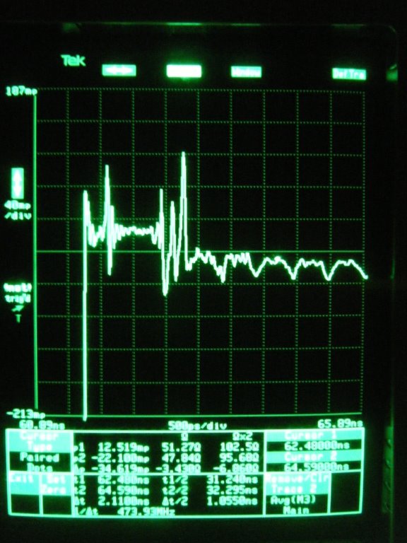
I have one cursor on the semi-rigid coax and the other cursor on the straight section of the coplanar waveguide. The measured impedances are 51 and 47 Ohms respectively.
If I move the second cursor to the bend on the coplanar waveguide, the measured impedance drops to 46 Ohms as shown in this measurement.

The impedance is slightly lower than 50 ohms. This could be due to the solder mask as suggested by Janne or the dielectric constant of the FR4 is not 4.7 as used in the calculation.
I also believe that some loss is visible in the TDR measurements.
I am sure that using an RF substrate instead of FR4 would give better results. I am also sure that building the high speed attenuator from ordinary 0603 and 0805 ($0.002) resistors is not the best. The idea is to try and see what you can do with ordinary parts.
It is quite remarkable that the Tektronix SD24 TDR is able to measure these discontinuities. The SD24 had a MRSP of $17,875 and the 11801 was about $20K (1990 dollars).
Jay_Diddy_B
Hi,
I am sure that using an RF substrate instead of FR4 would give better results.
Yes. With this signals you are far beyond the capabilities of FR4. I have never characterized FR4 up to this Frequency therefore I can't give you any numbers, but the tan-delta and permitivity will be quite off. I'd suggest you try some Rogers-Material or go for a semi-rigid-line instead of the CPW.
The fiber glass weaving in the FR4 is probably also visible in the TDR trace. For circuits running at several GHz on FR4 it is recommended to have the traces run at 45 degree angles to even out the impedance differences caused by the fiber glass.
The fiber glass weaving in the FR4 is probably also visible in the TDR trace. For circuits running at several GHz on FR4 it is recommended to have the traces run at 45 degree angles to even out the impedance differences caused by the fiber glass.
I am not experienced enough at these high frequencies to know if it is the fibre glass weave. I do know that more exotic materials are normally used for these frequencies.
At the self-generated frequencies the effect is not visible.
Is anybody aware of a place that will make boards using Rogers material at a reasonable price? The few places I looked wanted a lot of money.
I also looked for some SMD attenuators. I found these Susuma ones on Digikey:
Link:
http://www.susumu-usa.com/pdf/products_38.pdf I don't think that they are really good. Any alternatives?
Jay_Diddy_B
I was wondering if the impedance changes in the coplanar waveguide section were caused by glass weave (I don't think so, since each 6 bends was clearly defined and consistent) or by a non-TEM mode. How would routing the turns as 45 degree beveled right angles instead of arcs affect that?
I remember reading just a bit ago somewhere, maybe PCB-Pool, doing a pool of Rogers (or was it alumnium?)