Did a bit of tracing today trying to focus on the PFC and IC hoping to figure out the circuitry. Maybe, I should just call Corsair and ask. Some of the symbols were too complex, so I just made a note or a small pic when I didn't know what the "thing" is/was.
I was able to score one more identical broken power supply and one more very similar broken PSU from the same manufacturer! Should be a very inexpensive lesson in microelectronics.
Will catch up on responses later today I hope. Click image below then click it again when it takes you to the new page to really zoom in close.

Does the 25v Cap look burned?:

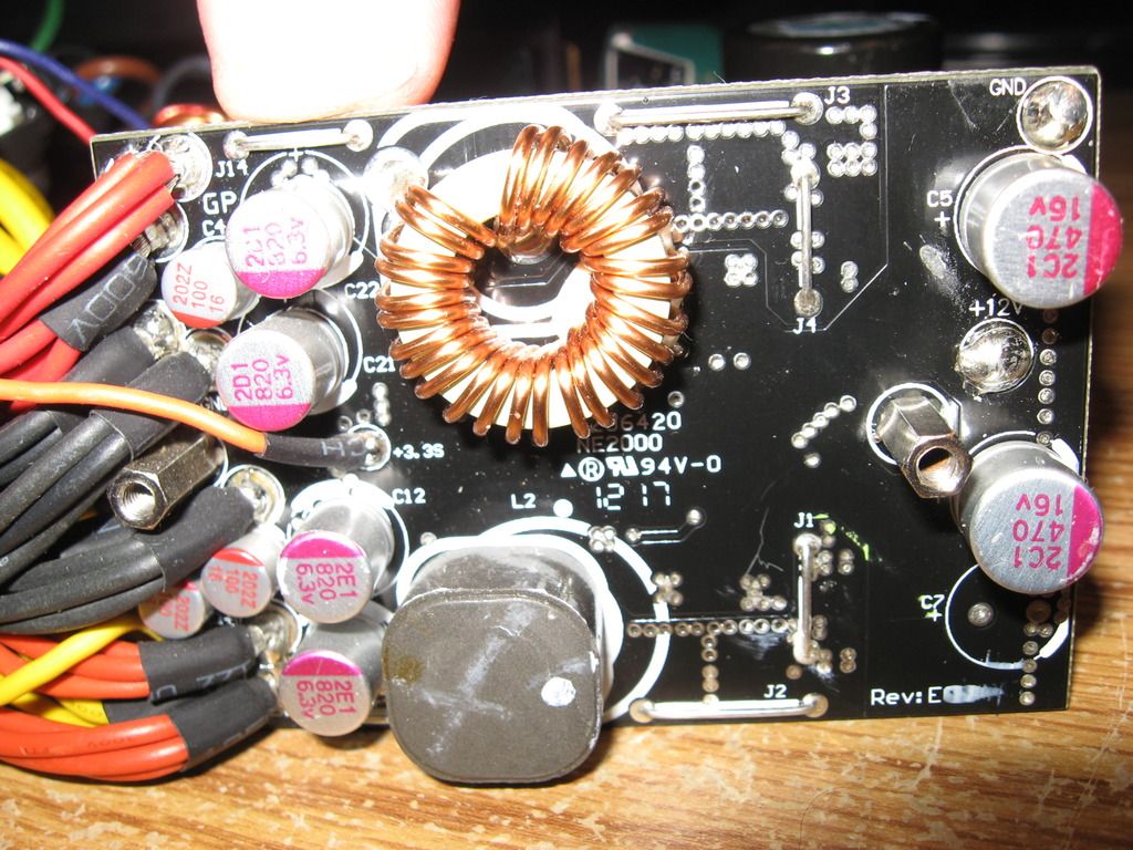
Other Side of PFC Board:

Will start tracing at the optocouplers next time.
The color is like ink that runs across onto the PFC controller next to it on the left-just noticed in the photo. Was sure hoping I could find a problem somewhere obvious, replacing that PFC controller does not look like fun. Getting my hand pump on there does not want to extract the solder with the tight pin configuration. Oh well that is in the future.
Ordered cap tester a few days ago....going to be a long wait.
I would assume it more likely that some issue that will not involve replacing the PFC IC or module would be more likely.
I think the thing to do while the system is apart is to
(a) Inspect it.
(b) trace it to know the most relevant connections
(c) identify / arrange possible points of in-system test access to relevant nodes so you can check the states at run-time
(d) perform any individual component or sub circuit testing that seems possible and necessary.
Otherwise soon I think you should put it back together and then identify the operational voltages at the control and signal nodes that you will have identified so you can determine a cause of why the PFC has no output.
Then, having established the circuit input that may be at fault, look for a way to prove / repair that aspect.
This is music to my ears. While tracing the opto circuits on the primary side I was thinking about pulling them for a simple bench test in a bread board.....only 4 terminals and I have a few major components already off. Although not sure how sensitive they are to heat.
Really good article on the power supplies explaining PFC. Got a good laugh at a complexity comment on page 3, "Reduced complexity for active PFC...." Circuitry on this board is wow.
I noticed that when you click my thumbnail images posted at postimg.org you can actually download the original in full resolution and zoom in. Excellent website for the larger photos.
Here is some of the optocoupler circuitry:

I originally thought this "chip" had some burn, but not so sure now. Wanted to post to get other opinion(s).

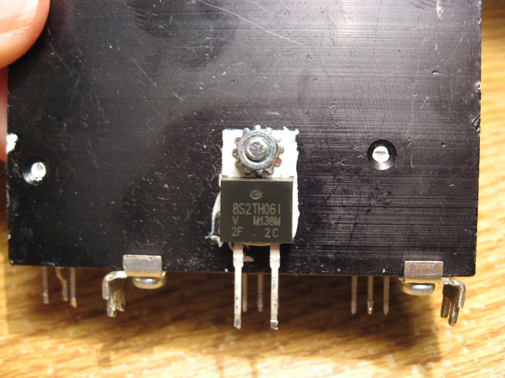
Boost diode ^^^ tests good "854" with negative probe to terminal 1 and "1" with negative probe to terminal 2-red always on other terminal.
Corsair CX500 PSU Repair - YouTube
Interesting fix for sure; very informative, especially for that PS229 chip. He did have power on all of the rails, where I had nothing. I can sure see something like that as one possibility with mine.
I wonder if that PS229 will fail prematurely since he had to increase the voltage through the pin to get a "signal" across to the other side....?
Fuse is/was a ceramic 250v 12A; "LF.T12AH250VP"
Is it slow-burn or fast?
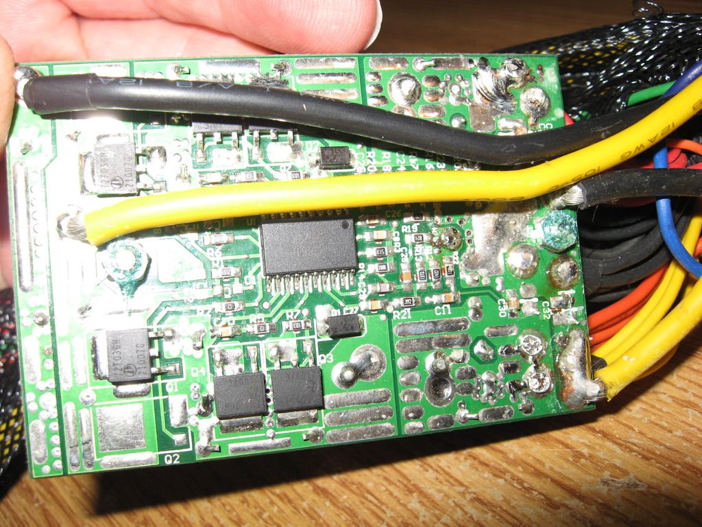
Running out of steam. Eliminating all the small resistors now and trying to get just the main things like transistors, optos, transformers, caps, and output circuits to that sub-board. It appears the main board is supplying +12v+ to that board off to the side which then supplies +5v and +3.3v to peripherals.
*Some peripherals still receive +12v directly from the main board.

The second PSU with the same model number arrived, but it is from 2011 and the board is way different.
Here is the board off to the side: