Hi all,i have just built a aliexpress 150 watt electronic lm324 kit,the most it will sink is 5a with a 15v input,only 2 of the ceramic resistors going to source of each fet gets warm so i suspect faulty fets,can anyone recomend a good sub?,cheers.
do you have more details?
there are more than one electronic loads out there..
its this one if it helps.
What FETs did you use? Were they included or did you source them.
Can you measure the voltage on the gate of each FET to see any differences?
FWIW, there is a thread on here (commented on recently) about upgrading that Chinese load kit.
the drive to the fet gates looks to be equal for all 4 fets,they are what came with the kit.
Fets will usually fail short. So failed FETs are more like sinking too much current and things go well blow the resistor with no further damage.
A point to check are the resistors - the cold ones may be open circuit.
A way to check the individual channels is to force the other channels to off, e.g. by shorting the gate to ground. This way one should be able to test individual channels. Doing this for 3 channels would be an option to also add a lower current range.
Yeah that circuit is pretty basic/low budget. I found some quality brand name schematics for 150/300W models, this winter I should spend the moeny on a proper case, heatsink and mosfets, and build it. That had an MCU, but it wasn't required, it was more for control and a screen. I think it's some guy called Kerry Wong, his website/youtube videos
There's also a nice 1 on youtube where the guy design's one with ADC/DAC's, and iirc, it was good for 10mV/10mA steps, without costing a fortune either. And they should be pretty scale-able.
well its now working sort of but the max it will sink from a 30ah car battery at 12.2v is 6a so about half what its supposed to do,guess i need to increase the 220k resisters on the gate voltage devider ckt?
Does the op-amp outputs goto max ? I'd try making that 1k gate divider a lot smaller 1st, so that's closer to the actual op-amp output level, if that's a problem.
I bought 20 mosfets for a load project, and I killed 2-3 of them just testing them on a heatsink, and it was well below the power I expected them to handle. I think that was the plate steel heatsink I tried, the heat flow is too slow and the mosfet cooks at any useful power.
well its now working sort of but the max it will sink from a 30ah car battery at 12.2v is 6a so about half what its supposed to do,guess i need to increase the 220k resisters on the gate voltage devider ckt?
Sinking 6 A at 12.2 V is already quite some power. So it may be a good thing that the current does not go higher.
Chinese circuits tend to be a bit overly optimistic - so it is not a good idea to go beyond the specs, usually even better to no even get to close to the limits.
In this case the problem is more high power at a higher voltage like 50 V - in this cas 1 A may already be too much and blow things.
6 A may be about the limit if the circuit. With some care and as long as the voltage is below some 15 V or so one may switch in a 2nd resistor in parallel to R22 to allow for a higher current. Ideally there would be some protection to not allow this with a higher voltage.
Does the op-amp outputs goto max ? I'd try making that 1k gate divider a lot smaller 1st, so that's closer to the actual op-amp output level, if that's a problem.
I bought 20 mosfets for a load project, and I killed 2-3 of them just testing them on a heatsink, and it was well below the power I expected them to handle. I think that was the plate steel heatsink I tried, the heat flow is too slow and the mosfet cooks at any useful power.
Very few modern Mosfets are meant for linear mode. Most have limited DC SOA and will fail in an electronic load.
One that is used in commercial devices and working here in a similar setup is Irfp250n.
well its now working sort of but the max it will sink from a 30ah car battery at 12.2v is 6a so about half what its supposed to do,guess i need to increase the 220k resisters on the gate voltage devider ckt?
In a simplest form of the circuit, the control input voltage {i.e. the (+) opamp input} appears across the sense resistor.
The opamp will try to make V2 equal to V1. Whereby, you can calculate the current draw through each MOSFET.
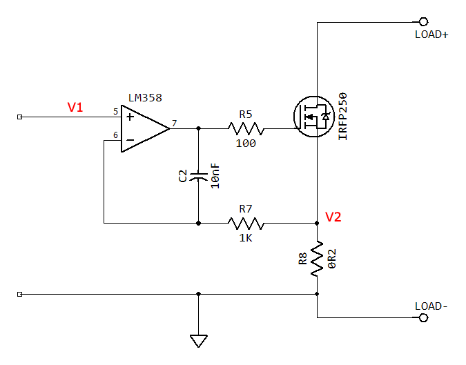
Here's a more readable version of your circuit:

could an IGBT be used instead of a mosfet?.