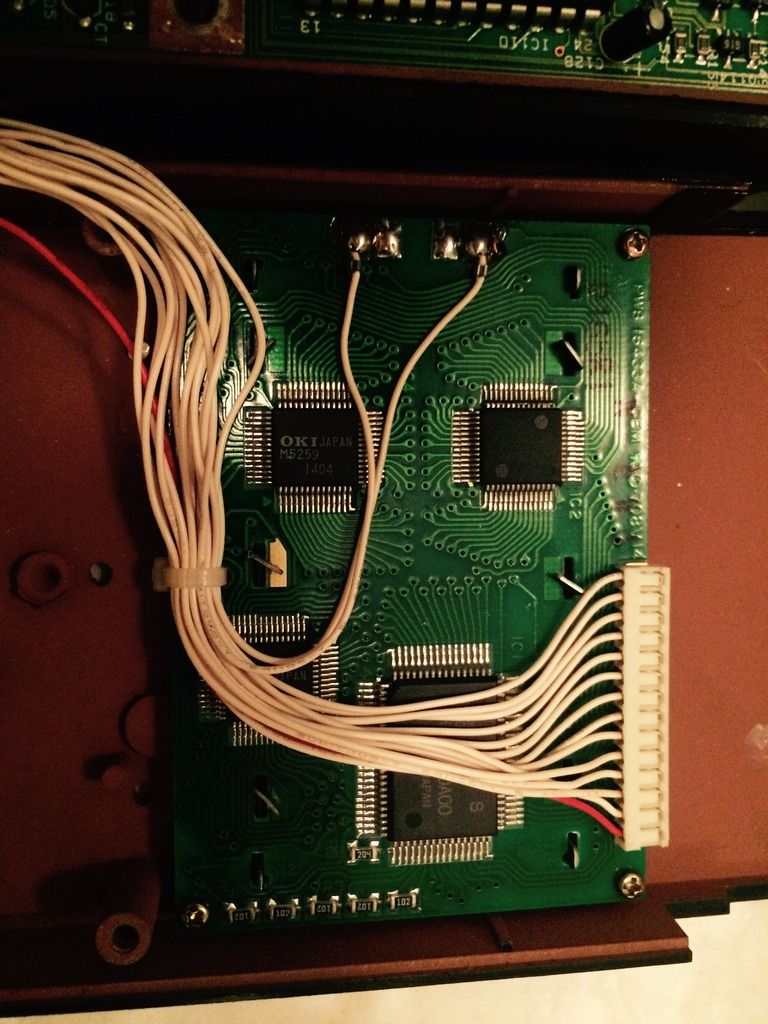
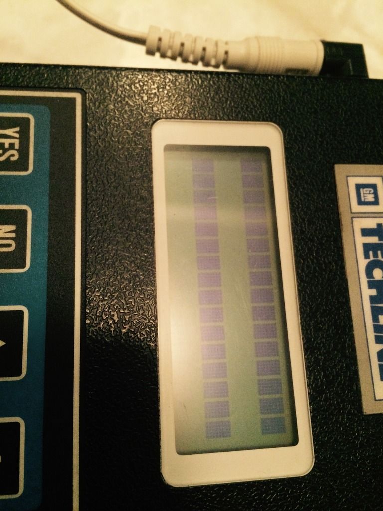
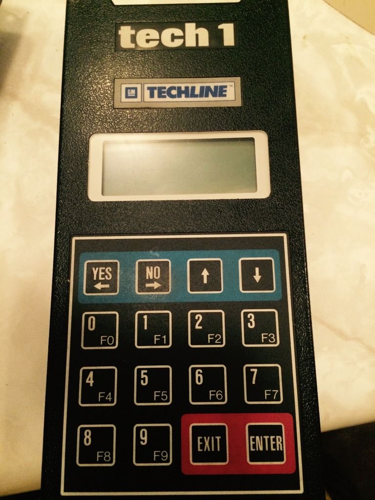
LCD blank lines says the LCD controller is not being initialized (very basic functionality).
Because of this (and good policy anyway), I'd be checking all on-board voltages look like they belong where they are supposed tp be... e.g. +12V +5V / 3V3 on logic chips etc.
Check the backup battery still has a charge as well - it may be holding something down.
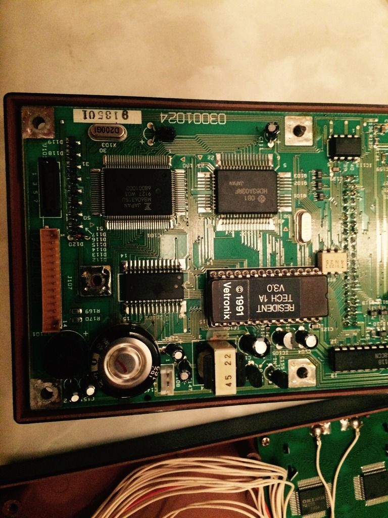
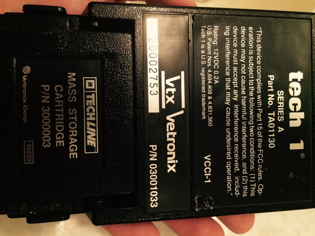
The fact the 'master cartridge' is required for power-on may have some loop-through (in the cartridge) before the unit initializes - so check that as well...
Next would be to look (with scope) for any clock-like signals around the CPU & interface chips to have some assurance that they are alive. Datasheets help, but not immediately necessary at this early stage.
Check any on-board fuses, capacitors, etc that may have left the building before you got there.
The next step will need you or someone to start identifying the logical parts of the circuit to look for signs of life - then drill-down to test & repair specific symptoms.
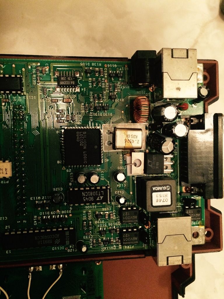
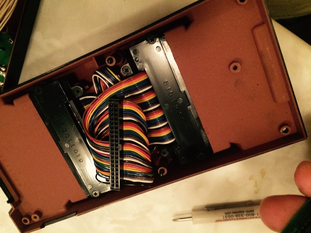
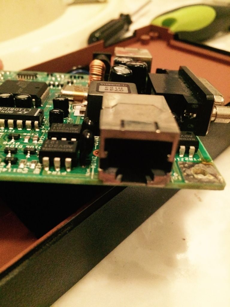
Is that supercap backup capacitor leaking or is it glue underneath? Check it anyway, have seen many of those leak and cause corrosion damage to boards over the years..
Is that supercap backup capacitor leaking or is it glue underneath? Check it anyway, have seen many of those leak and cause corrosion damage to boards over the years..
Seems like glue. Looks like the same stuff around that transformer. It holds voltage around 1V after being shut of for awhile is that good. It sees 5v when powered.
LCD blank lines says the LCD controller is not being initialized (very basic functionality).
Because of this (and good policy anyway), I'd be checking all on-board voltages look like they belong where they are supposed tp be... e.g. +12V +5V / 3V3 on logic chips etc.
Check the backup battery still has a charge as well - it may be holding something down.
The fact the 'master cartridge' is required for power-on may have some loop-through (in the cartridge) before the unit initializes - so check that as well...
Next would be to look (with scope) for any clock-like signals around the CPU & interface chips to have some assurance that they are alive. Datasheets help, but not immediately necessary at this early stage.
Check any on-board fuses, capacitors, etc that may have left the building before you got there.
The next step will need you or someone to start identifying the logical parts of the circuit to look for signs of life - then drill-down to test & repair specific symptoms.
I was checking voltages and couldn't seem to find 3.3V most of what I could find is input voltage, 5V and 1.2V. Although one of the pins of that square box which I thought was a relay has 17V. The back light voltage seems really low to me since it appears to be coming out of a transformer at 1.2V. I am getting input voltage into the voltage reg. but it is outputting 1.2v on two of its pins.
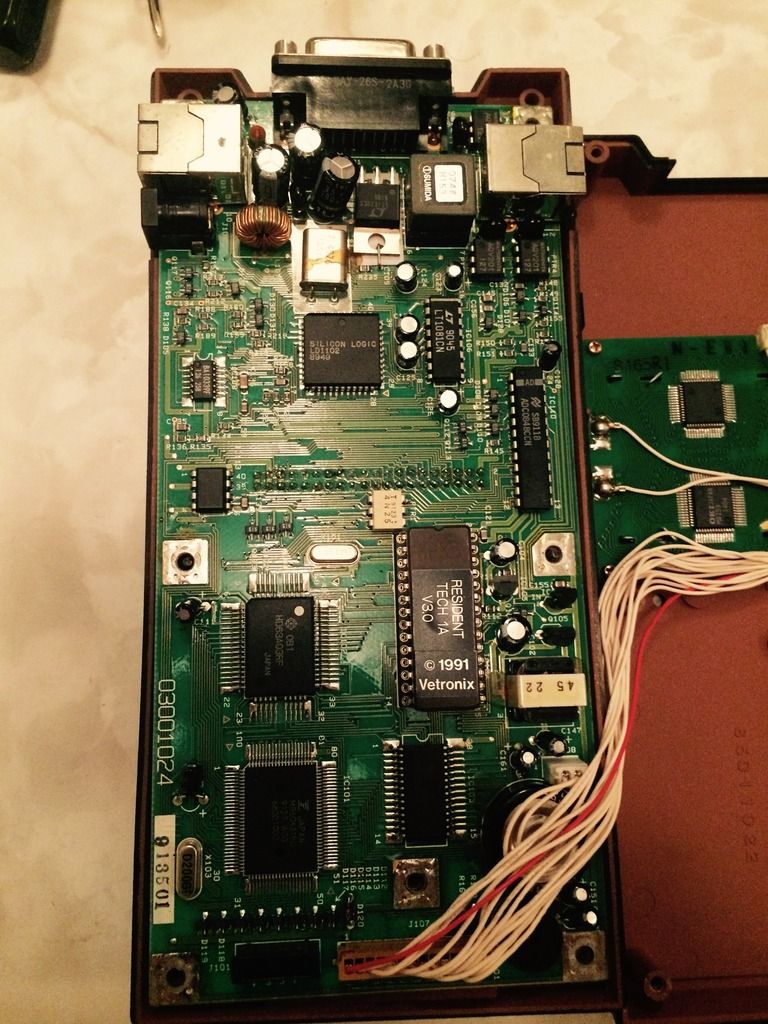
I took apart the cartridge it has a Vetronix chip on one side and six Intel flash chips on the other side with a few surface mount caps.
Without being disrespectful, it seems like the diagnosis required may be a bit beyond your level. Knowing 'where' to look is just as important as 'what' to look for.
It's difficult giving advise in this 'remote manner', as a fundamental knowledge of how a circuit (any circuit) is arranged will get you more than half way to identifying the possible problem areas.
That particular device could easily be pre-3V3 vintage, but you could look for the power supply stage (inj and out), and the +Vcc pins on major chips to see what's happening there - but one slip of the DMM probe can easily turn the whole device into a 15 year old paper-weight.
Finding +5V is good, +17V seems a little high, (maybe 12V x1.4 = not unreasonable). +1V2 to the back-light could be averaged PWM for a dimmable back-light - hard to tell without a scope.
So the next thing may be to see if you can find any 'clocks' or data running around the major logic chips.
Don't be afraid to step back and ask someone nearby for physical help...!
Try measuring the backlight on AC. With that vintage it's probably an EL panel.
Without being disrespectful, it seems like the diagnosis required may be a bit beyond your level. Knowing 'where' to look is just as important as 'what' to look for.
It's difficult giving advise in this 'remote manner', as a fundamental knowledge of how a circuit (any circuit) is arranged will get you more than half way to identifying the possible problem areas.
That particular device could easily be pre-3V3 vintage, but you could look for the power supply stage (inj and out), and the +Vcc pins on major chips to see what's happening there - but one slip of the DMM probe can easily turn the whole device into a 15 year old paper-weight.
Finding +5V is good, +17V seems a little high, (maybe 12V x1.4 = not unreasonable). +1V2 to the back-light could be averaged PWM for a dimmable back-light - hard to tell without a scope.
So the next thing may be to see if you can find any 'clocks' or data running around the major logic chips.
Don't be afraid to step back and ask someone nearby for physical help...!
You are most likely right I don't have much test equipment and I don't know any one local that I can ask for help.
Try measuring the backlight on AC. With that vintage it's probably an EL panel.
You are right thanks! It runs 30V AC.