-
Actually, my memory does still work properly. Zoom in a bit and watch for a while and the instability of the lock reveals itself.
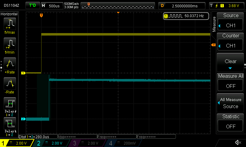
280μs after.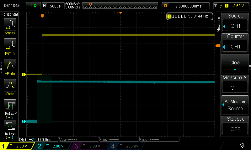
-170μs before.
So in my case, I have a +280μs / -170μs variation around the locked point and it can swing from one extreme to the other and back again in just a few seconds. Maybe I'm expecting too much to think that it should be able to lock and hold the lock considering how small the variation is in mains frequency.
-
Obvious questions.
Have you checked the noise on power lines in that area?
Is there noise on the varicap control voltage?
Have you checked whether C101 C102 have dried out? -
Actually, my memory does still work properly. Zoom in a bit and watch for a while and the instability of the lock reveals itself.
280μs after.
-170μs before.
So in my case, I have a +280μs / -170μs variation around the locked point and it can swing from one extreme to the other and back again in just a few seconds. Maybe I'm expecting too much to think that it should be able to lock and hold the lock considering how small the variation is in mains frequency.
Grize, I'll do the same experiment tomorrow, but the quick check I did today seems to replicate what you are seeing almost exactly.
tggzzz C101 and C110 are a tants and C102 is an aluminum so all worth a check as this board runs like an oven!
(Still trying to track down the cause of the transient Glug Death when powering on).
-
Obvious questions.
Have you checked the noise on power lines in that area?
Is there noise on the varicap control voltage?
Have you checked whether C101 C102 have dried out?
Well, as you can see from post #74, the purple trace is the control voltage and it looks like there's about 300mV p-p of noise there. However...
Here is where you find TP402 on this board: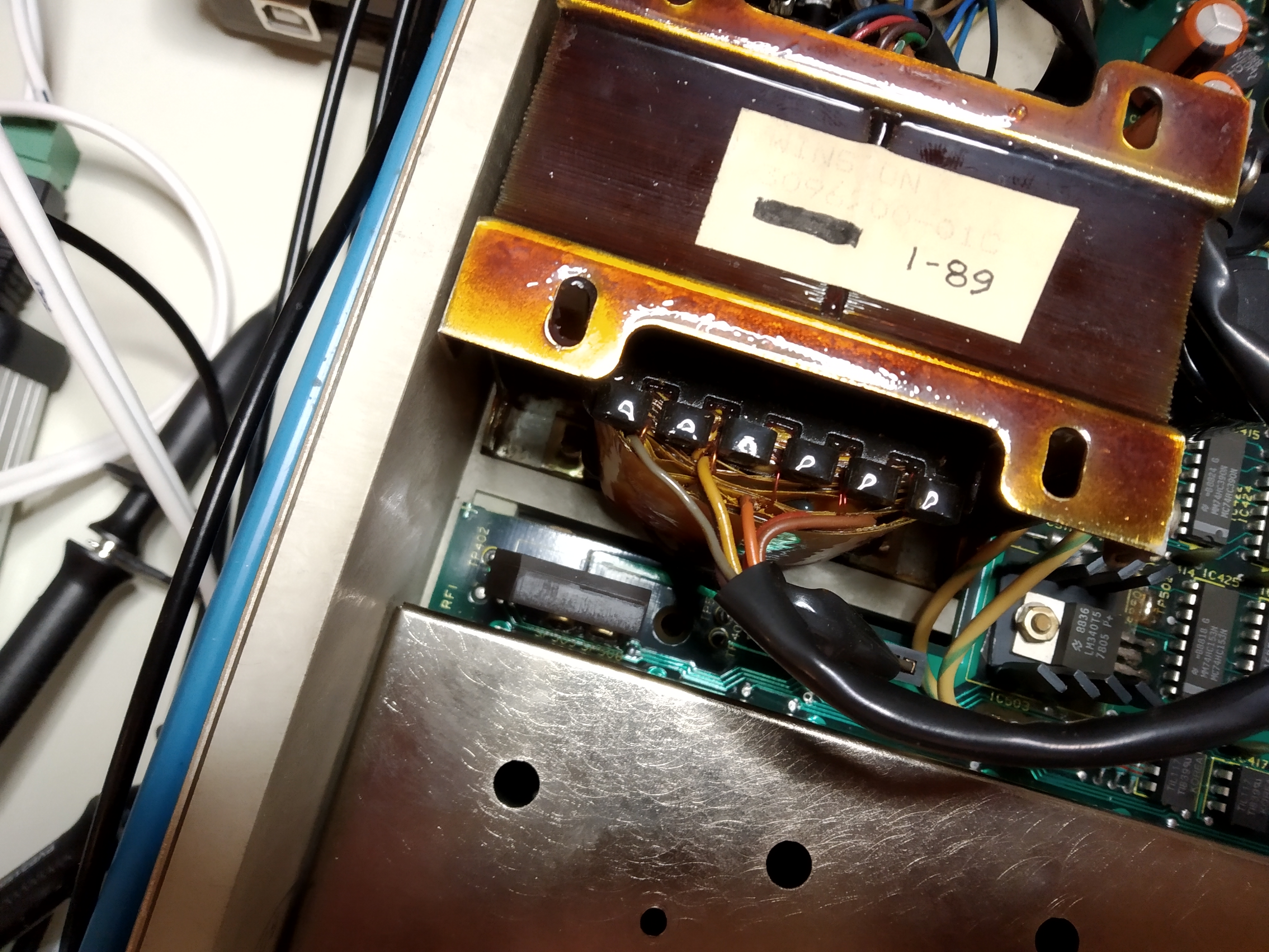
Sitting right next to that bridge rectifier and the mains transformer, I can't exactly imagine it being particularly quiet either!
C101 is a dipped bead tantalum and C102 is a metal cased wet tantalum. They both look OK, but when the Peak ESR70 tester I have on the way to me arrives, I'll test both to see if they are still within reasonable limits.
I've checked all the power rails on both analogue and digital boards and there is no significant ripple on any of them.
-
One other thing I have noticed about this meter which is worth bearing in mind is that the very convenient fasteners which hold the top cover down are actually a hidden danger.
The fasteners grip the steel pin which runs through the middle of the hole in each receiver: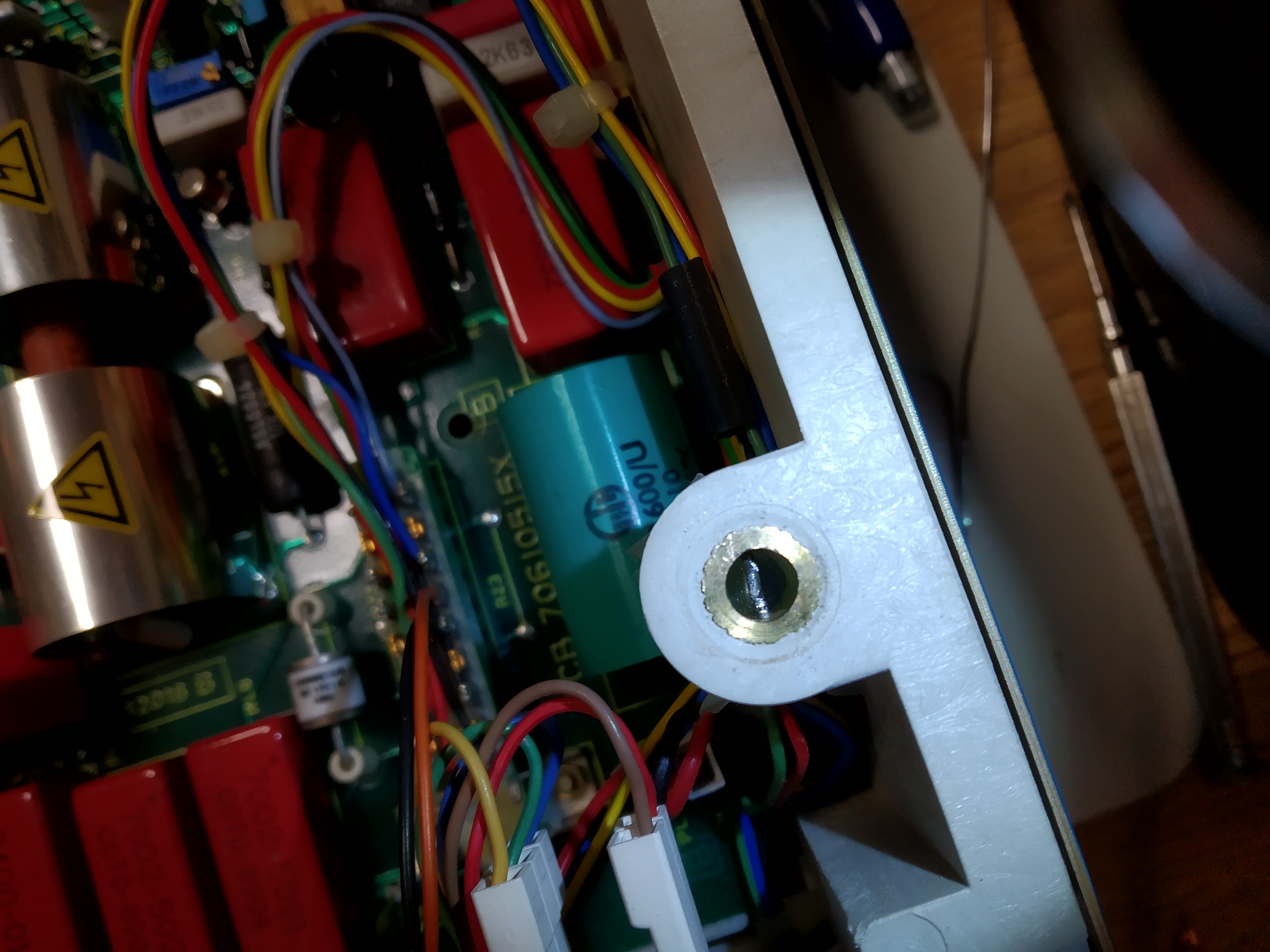
The danger is that every time you open and close the case, the friction between the two metal parts shaves off tiny flakes of metal. For three out of the four points, there are PCB traces and sensitive circuit paths right below the receiver and when I inspected the PCB at these points under a strong light, I could see tiny glittering flakes of metal on the PCB!
The solution is to just put some adhesive tape at the bottom of each receiver to stop the metal dust before it falls on the PCB.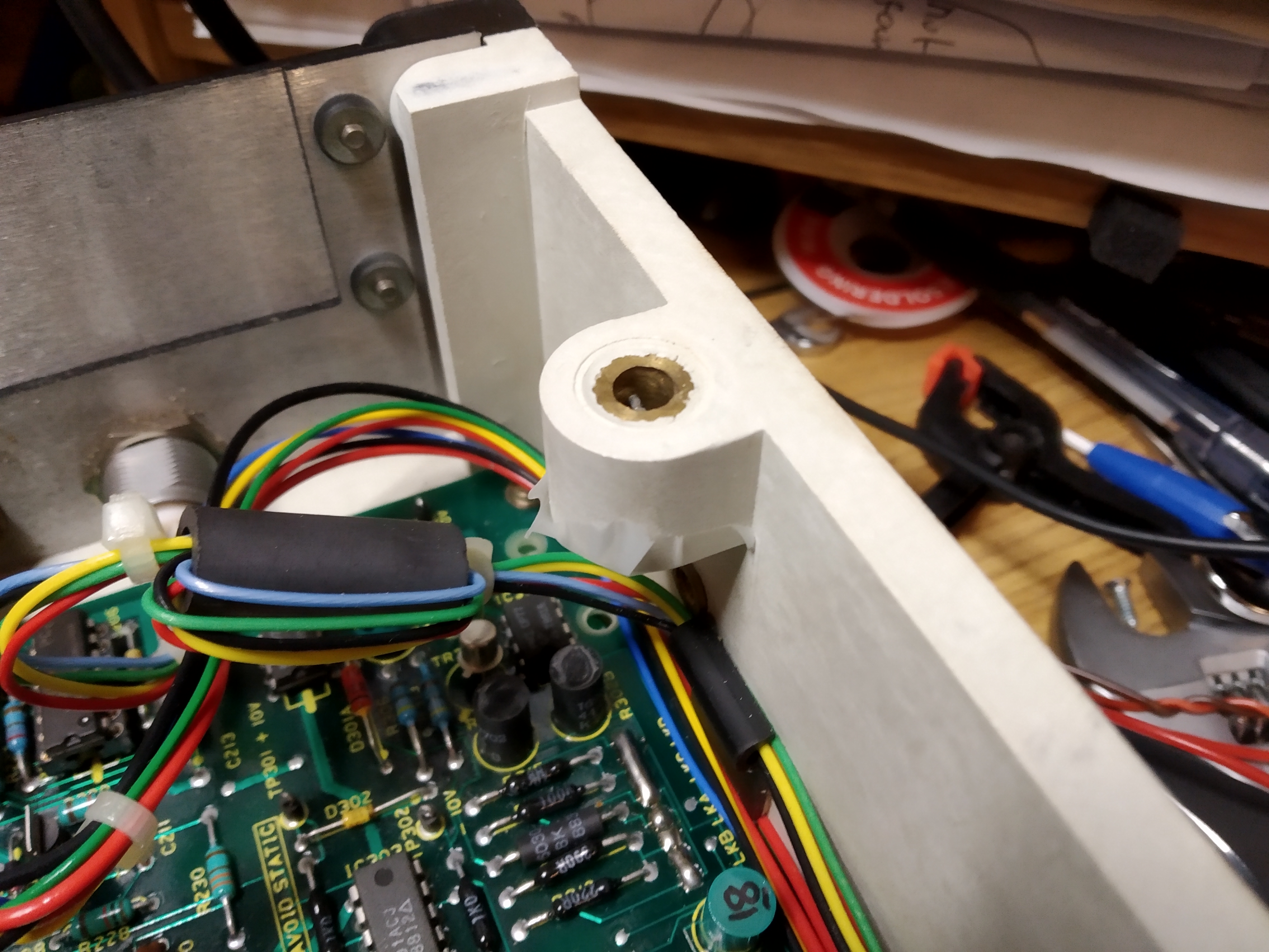
-
tggzzz C101 and C110 are a tants and C102 is an aluminum so all worth a check as this board runs like an oven!
You're not kidding about how hot the clock dividers sections gets! Even with the top off now while I've been collecting these traces, the metal box gets so hot it's uncomfortable to touch it. Your screening box doesn't even have the holes in it that mine has so I hate to think how hot it gets in there.
It may be worth doing what they did on my later model meter and drilling some holes in the lid. It may extend the life of the parts that live inside the box.
-
Sitting right next to that bridge rectifier and the mains transformer, I can't exactly imagine it being particularly quiet either!
Probably helps mode locking onto the ~50Hz
-
... So in my case, I have a +280μs / -170μs variation around the locked point ...
Grize, I'll do the same experiment tomorrow, but the quick check I did today seems to replicate what you are seeing almost exactly.
If you're seeing a similar variation, then I'd have to say that this is perfectly normal and is neither the cause of your initial glug death, or the (to my mind) excessive noise on my 10V range. It's a red herring.
-
Sitting right next to that bridge rectifier and the mains transformer, I can't exactly imagine it being particularly quiet either!
Probably helps mode locking onto the ~50Hz

-
For comparison one could check the jitter on the 50 Hz mains signal send to the PLL: look at the slope some 1 second after the trigger point with some persistence. A reasonable DSO should be able to do this.
The position of the PLL and testpoint 402 is really not good - quite close to the transformer, so one might get magnetic coupling and thus 50 Hz FM modulation on top. If right at the phase comparator output this point is a sensitive point and should be well shielded.
I don't think the filter caps in the loop filter should be so critical. Tantalum caps usually fail short, but not with slowly rising ESR. LOW ESR is likely also not really needed. It would be more the capacitor at the supply that could be a problem. -
Actually, my memory does still work properly. Zoom in a bit and watch for a while and the instability of the lock reveals itself.
280μs after.
-170μs before.
So in my case, I have a +280μs / -170μs variation around the locked point and it can swing from one extreme to the other and back again in just a few seconds. Maybe I'm expecting too much to think that it should be able to lock and hold the lock considering how small the variation is in mains frequency.
Mine is very similar, so possibly red herring
I haven't yet took out PCB8 to set the 49mhz accurately against freq counter / GPSDO and the lock does drift backwards and forwards over about 5 seconds
Meter has only been on for about an hour, lid is off the clock enclosure.
Variation after a few mins is -221us / +482us
What I did notice it takes "forever" for it to lock on power on. Quite hilarious to watch the second trace whizz back and forth for over 20 seconds until it stabilises.
Could be due to not having the clock set close nominal free running frequency and the PLL having to work hard resulting in the Glug Death until it locks? Glug death only flashes up for about 4 secs and previous test the glug death signal is only high for about 0.8 secs on start up anyway, so not sure if this is related.
I see about 0.2v ripple on the 5v supply at the pins on the clock board.
Good spot on the swarf emitted by the cover screws
[ Specified attachment is not available ]
-
I don't think the filter caps in the loop filter should be so critical. Tantalum caps usually fail short, but not with slowly rising ESR. LOW ESR is likely also not really needed. It would be more the capacitor at the supply that could be a problem.
I don't disagree, but would a tant on the way to becoming a short exhibit increased leakage? If so, could that affect the loop, either because of a R101/2/3-to-leak "potential divider" shifting the lock range, or by introducing droop? -
I just timed how long it takes for mine to lock from power on and it took around 13 seconds. (The meter was stone cold as well, this being the first power up of the day.) So I'd say it was unlikely that seven more seconds to lock would explain your glug death problem.
My trusty Brymen 867 measures the supply to the oscillator board at 5.06V with 0.005V ripple.
The control trace really isn't that well positioned. The PLL and phase comparator is the second chip to the right of the linear regulator with the heatsink just to the right of the transformer in this picture:.jpg)
The control trace from the 4046 comes out on the bottom of the PCB and then pops up to the top through a via just at the right hand end of the shielding box. Then it runs along the side of the box to the test point and back to the bottom of the PCB again where it comes up through the PCB to the pin which connects it to the oscillator board.
Taking the oscillator board out shows this: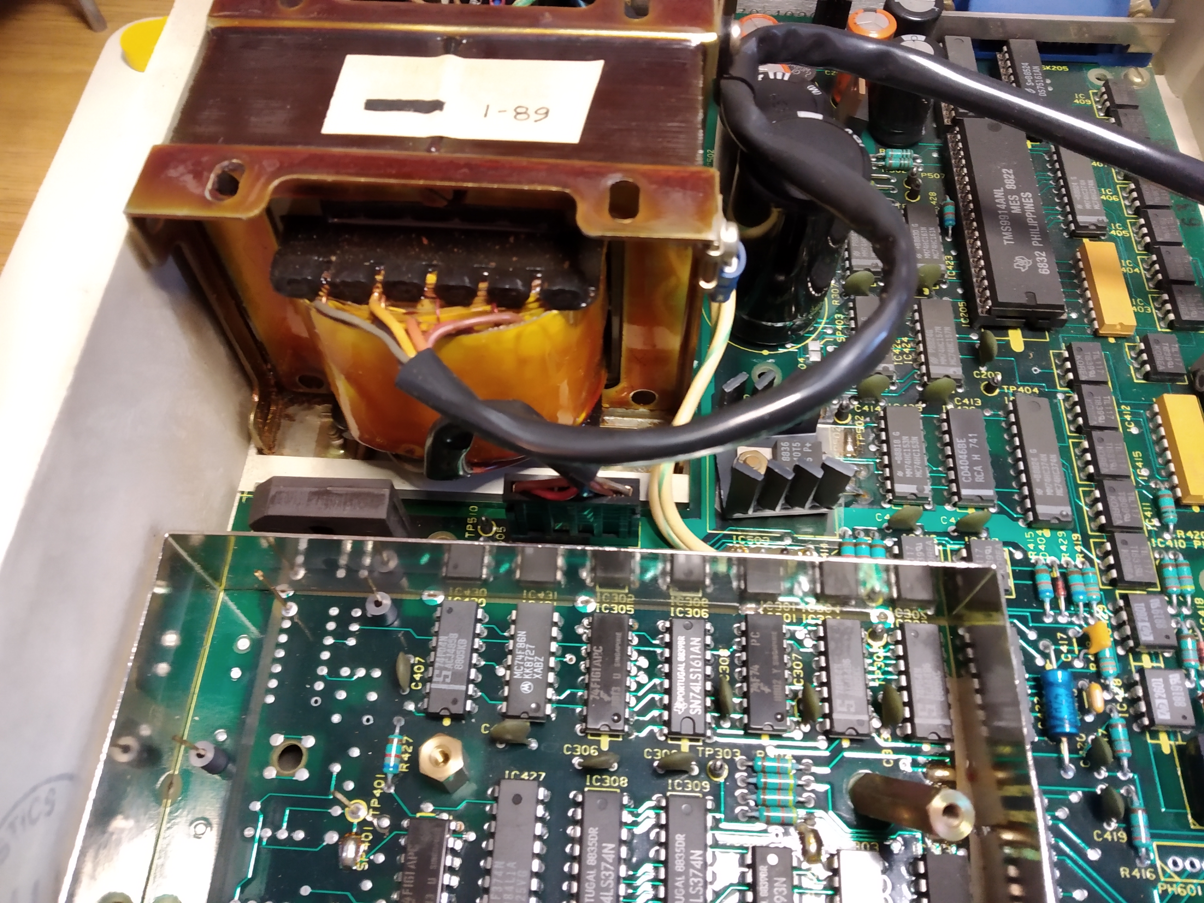
The control signal is the pin at the far left of the shielding box and it's interesting to see that on my 7061 at least, Solartron have placed a little ferrite on the control signal and 5V supply pins. They look very much like an attempt to mitigate some of the noise coming in on those two pins.
You probably don't have those on yours Dek, what with it being an older revision. I wonder what that ferrite would do for the ripple on the 5V supply to your clock board... -
Humm,
Checked the 5V DC supply on the boards again, this time with the Fluke, 4.995V and 1.236 mv ripple.
Also checked under the clock board, it has the same ferites.
I checked TP101 again and the clock frequency jitters terribly. Its almost impossible to determine an accurate reading.
Using the stats on the scope Min 48.3 and max 49.75mhz.
-
Could be due to not having the clock set close nominal free running frequency and the PLL having to work hard resulting in the Glug Death until it locks? Glug death only flashes up for about 4 secs and previous test the glug death signal is only high for about 0.8 secs on start up anyway, so not sure if this is related.
If your oscillator board is way off frequency, it might explain the much larger variation that you have once the PLL actually locks and possibly explain the slightly longer time to lock from power on. I doubt it has anything to do with your glug death though as all the glug timing is derived from the main clock. Logically, if it's a bit fast or slow when it starts, the rest of the timing will also be affected the same way and it shouldn't make any difference.
I'm thinking that your glug death problem lies somewhere with IC313. I notice it has two split pads on the outputs - SP303 and SP302. On my machine, both are soldered. The -CLR signal which is supposed to reset the watchdog so that it doesn't assert GLUGDEAD comes from IC313 via IC314 and has a test point at TP304. IC424 plays a key role in switching the glug timing between the full speed forcing wave frequency of 24KHz for 4 digit measurements or the much slower 1.5KHz speed used for more digits. If there's anything that's not 100% with IC424, it could mess up all the timing as the whole circuit starts up.
I'm grasping at straws here as the whole timing circuit is very complicated, but there does seem to be some condition which isn't established properly as your meter starts up, so these areas would be good places to look at.
Just saw your new post as I went to post this. That ripple really doesn't sound nice, nor does the jitter. I'd certainly be having a look at the smoothing capacitor for that 5V rail. You do have a nice ceramic package there for your VCO chip, while mine is the humble plastic package. If you have a signal generator that you can generate a 49.152MHz sine wave with, it would be an interesting test to pull the clock board out and inject 49.152MHz from the signal generator at the clock board's output pin and see if it makes the glug death problem go away. It would, at least, determine if the clock board is the problem or not.
-
It is quite normal that the PLL lock take quite some time, as the filter is relatively slow with caps of 1 and 22 µF and 100 K resistors.
I would not expect the PLL lock to effect the GLUG dead signal. This would more like the input amplifier coming out of saturation slow on start up and maybe the supplies coming up in a slightly different sequence / speed.
The placement of the 4046 for the PLL is really odd. With resistors in the 100 K range I would consider the VCO control signal sensitive, even if there is a 1 µF capacitor. I think this deserves a .
.
Leakage of the capacitors at the filter would at first one cause a phase shift and this should not effect the ADC.
The nasty part would be some signal from the comparators / forcing signal to couple into the PLL - this could cause extra INL errors.
The ceramic vs. plastic case for the VCO chip should not make much difference - this part is not about precision or lang time stability. -
The placement of the 4046 for the PLL is really odd. With resistors in the 100 K range I would consider the VCO control signal sensitive, even if there is a 1 µF capacitor. I think this deserves a
.
I agree and I won't waste any more time on it. As I now have a 49.152MHz crystal, it's time to dig into my parts drawer for some capacitors and replace the oscillator board with it and completely ignore the PLL, just like Solartron's optional crystal oscillator does.The ceramic vs. plastic case for the VCO chip should not make much difference - this part is not about precision or lang time stability.
The only thing the ceramic package normally gives is a larger working temperature range. As Dek doesn't have any ventilation holes in his screening box, the ceramic package was probably needed to cope with the temperatures inside.
-
If your oscillator board is way off frequency, it might explain the much larger variation that you have once the PLL actually locks and possibly explain the slightly longer time to lock from power on. I doubt it has anything to do with your glug death though as all the glug timing is derived from the main clock. Logically, if it's a bit fast or slow when it starts, the rest of the timing will also be affected the same way and it shouldn't make any difference.
I'm thinking that your glug death problem lies somewhere with IC313. I notice it has two split pads on the outputs - SP303 and SP302. On my machine, both are soldered. The -CLR signal which is supposed to reset the watchdog so that it doesn't assert GLUGDEAD comes from IC313 via IC314 and has a test point at TP304. IC424 plays a key role in switching the glug timing between the full speed forcing wave frequency of 24KHz for 4 digit measurements or the much slower 1.5KHz speed used for more digits. If there's anything that's not 100% with IC424, it could mess up all the timing as the whole circuit starts up.
I'm grasping at straws here as the whole timing circuit is very complicated, but there does seem to be some condition which isn't established properly as your meter starts up, so these areas would be good places to look at.
Just saw your new post as I went to post this. That ripple really doesn't sound nice, nor does the jitter. I'd certainly be having a look at the smoothing capacitor for that 5V rail. You do have a nice ceramic package there for your VCO chip, while mine is the humble plastic package. If you have a signal generator that you can generate a 49.152MHz sine wave with, it would be an interesting test to pull the clock board out and inject 49.152MHz from the signal generator at the clock board's output pin and see if it makes the glug death problem go away. It would, at least, determine if the clock board is the problem or not.
Unfortunately I don't have a sig gen that will run to 50mhz, only 25mhz so I think I'll leave the 49.152 clock signal for now. Appears that this is not the cause of the Glug Death (thanks Grize and Klein).
Might repeat what you did and set 3v on the clock control and adjust the frequency on the bench. I'll be able to check the noise and jitter to see if that is a incoming supply problem or just the smoothing on the boards itself.
The glug death is very consistent so should be possible to trace this with a methodical approach
It will be interesting to see the results of your crystal mod.
Dek -
Looking at the source of the 800ms delay on the clear signal line which is allowing the clock on IC315 to output the Glug Death on its Q4 output.
Comparing when the 3 / 1.5khz signal pulses start on the clock input of IC315 (shown green) and when the clear signal arrives on pin1 of the same IC, indicates a delay in the signal path back to IC310 -(shown in Red).
24.575mhz clock (derived from the 49mhz clock) on IC310 and IC313 appears simultaneously with the 3 / 1.5khz pulses on IC315 - so no problem there.
However, the QD output of IC310 is stuck low as is unused QC, but QB and QA show pulses. (shown orange) - could this be the source of the clear delay?
Haven't quite worked out what IC424 a quad multiplexer brings to the party yet, haven't found where the strobe and select lines are on the schematic! There is a note under this IC A -> Y= 4 NINES and B-> 5,6,7 NINES (shown in grey)
With IC310 output stuck 4 NINES are not being made?
Dek
-
I have to say, I'm starting to dislike whoever drew the circuit diagram of the 7061's digital board.

The choice between the 3A or 3B inputs of IC424 is made by pin 1 of the chip. That's actually located on the next page where the -4NINES signal is generated by the processor writing to the I/O port implemented by IC401 which is mapped into the memory space at address 0x100. Bit seven at that address lets the processor select 4 nines mode or not 4 nines mode.
Meanwhile, back on the previous page, IC301b is sampling the -GLUG signal at the full 49.152MHz clock rate. The output of IC301b is fed to the GLUG counter circuit and to the clock input of IC310 and to 3B on IC424. IC310 is configured as a simple counter and each rising edge on its clock pin causes it to increment the count by one. As the high bit of the nibble is connected to input 3A of IC424, then when -4NINES is asserted (low) the 3Y output of IC424 will receive the number of clock pulses fed to IC310 / 8. Otherwise, if -4NINES is not asserted (high) - (which should be the condition when the meter starts up in the default 5 digit mode) then input 3B of IC424 is selected and output 3Y then matches the output of IC301b (the -GLUG pulse sampler) and is not divided down.
IC310 is clocked all the time, so pin 11 should go high once for every eight rising edges at the CLK input on pin 2, regardless of whether the microprocessor has asserted -4NINES via the I/O port or not.
From what you are saying, IC310's two most significant bits are either not counting, or the outputs are blown.
The problem I see with this explanation is that IC310 only matters if the meter is starting up in 4 nines mode. I'm pretty sure that the default - when the meter displays "7061 INITIALISED" at power up - is 5 nines mode, so IC310 shouldn't matter. On the other hand, if the meter says "7061 RESUMED" at power on and it was in 4 nines mode when it was last turned off, then IC310 does matter.
What happens if you change the number of digits to 4 once the meter has recovered from its initial glug death? I'd expect it to go back to the glug death state again.
-
Here is pin 2 (ch1) and pin 11 (ch2) of IC310, from power up:
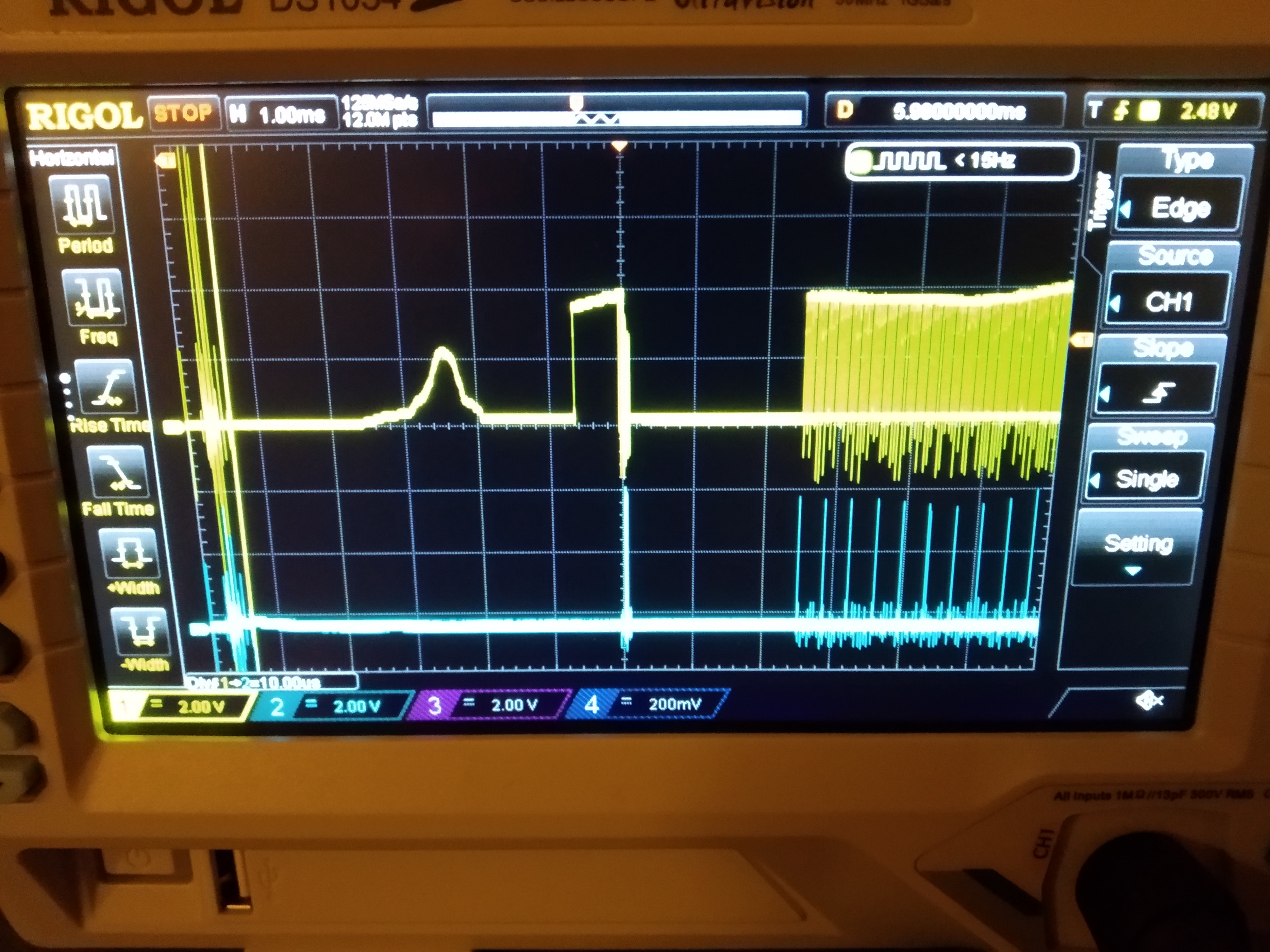
and zoomed in to the trace once both signals are running: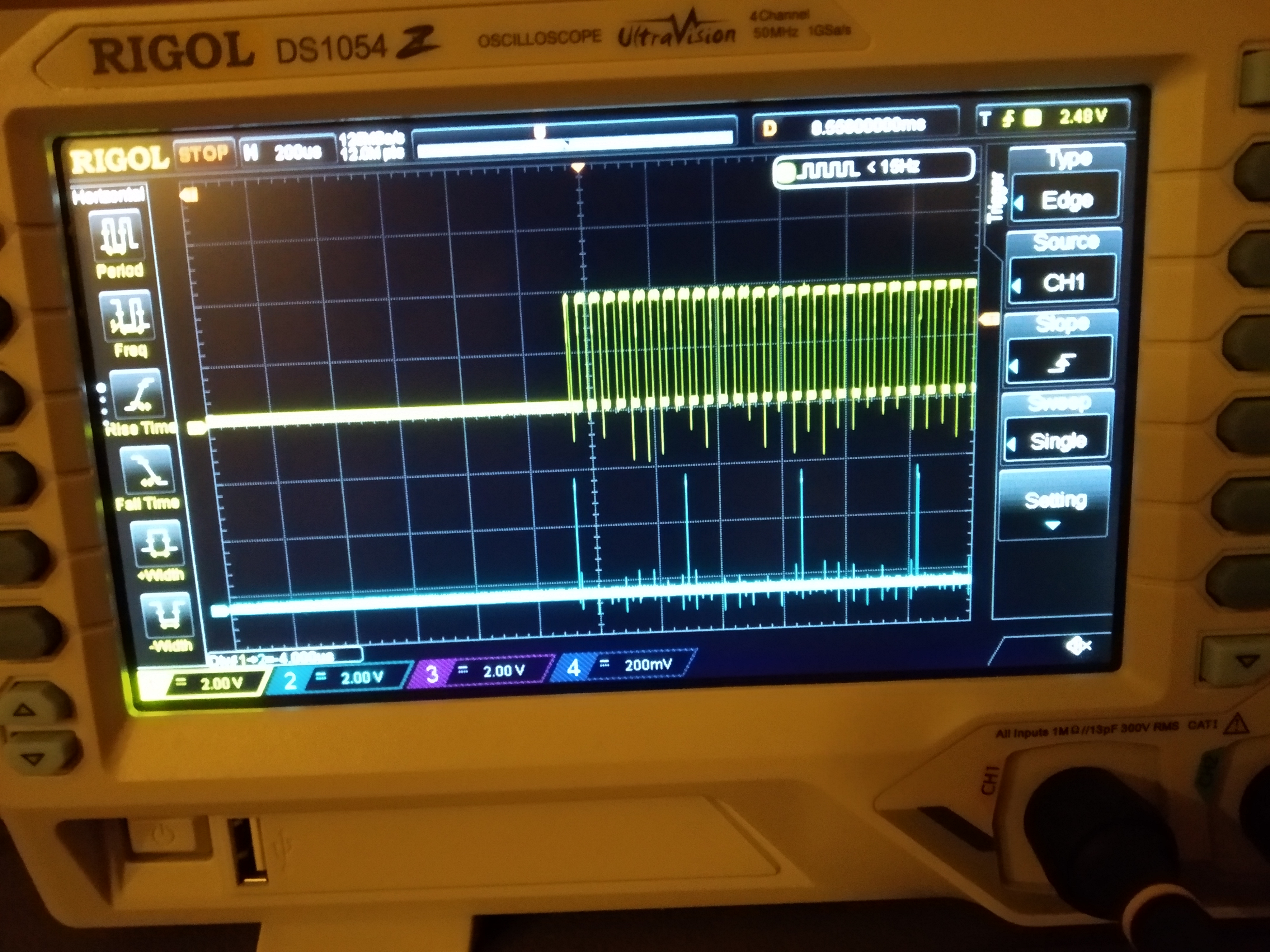
Sorry for the photos, but for some bizarre reason, the utility I have always used to grab screen shots from the Rigol suddenly bombs out trying to connect to the scope. The noise and over/undershoot on the traces is purely from my crap, but safe, probing setup.
-
It is well possible that during start up the 4 nines modes is used for a quick self test.
The scope trace from the start-up looks a little like there is something on that kind going on un the center of the screen.
A brocken IC310 is a possible explanation. Maybe also check to solder joints, not just QC,QD, but also the C and D inputs. -
Here is pin 2 (ch1) and pin 11 (ch2) of IC301, from power up:
and zoomed in to the trace once both signals are running:
Sorry for the photos, but for some bizarre reason, the utility I have always used to grab screen shots from the Rigol suddenly bombs out trying to connect to the scope. The noise and over/undershoot on the traces is purely from my crap, but safe, probing setup.
Switched the meter on this morning and without any scope connections, checked 4 digits - Overload message - switching back to 6 digits OK.
Shows overload on all ranges when in 4 digits.
I think you mean IC310
Checked the lines ABCD LD ENP ENT that are tied to 5v, all OK
Pin 11 and 12 low - no sign of life
Pin 13 and 14 nice 340ns pulses
I see the wide pulse on start up followed pulse train as per your screen shot, but nothing on Pin11
On one start up while the clips were connected to IC310, the meter turned on with no Glug Death and a proper self test and initialise. - I also seen the expected pulse train on pin 11.
Checked 4 digits again and same "OVERLOAD" message.
Rechecked pin 2 and pin 11 of IC310 and pin 11 still dead. ( tried triggering on pin 11, nothing apart from a slight ring on the falling edge of pin 2 squarewave)
This area of the board shows some signs of corrosion due to the proximity to the battery - I might resolder the pads of this IC and see if that makes a difference.
<edit> After posting this, checked 4 digits again and switches OK without OVERLOAD ERROR , still with Glug Death- pin 2 shows change from 1.5khz to 24khz
[ Specified attachment is not available ]
-
Yes, I do mean IC310. Sorry for the confusion.
I was wondering if this could be caused by leakage from the battery. In your trace where there is actually some life on pin 11, the spacing of the pulses is inconsistent, as is the level of them. I think we've found your problem! -
It is well possible that during start up the 4 nines modes is used for a quick self test.
The scope trace from the start-up looks a little like there is something on that kind going on un the center of the screen.
A brocken IC310 is a possible explanation. Maybe also check to solder joints, not just QC,QD, but also the C and D inputs.
Self test is a good explanation. The service manual does not discuss self test much, except to say that when it has a ROM set which makes the self test a manually initiated routine that it tests 1V and 10V ranges and lists the result as 4 digit values.