-
Hi everybody,
I recently purchased an inexpensive EIP 545B on eb (one of the devices recently sold from Israel).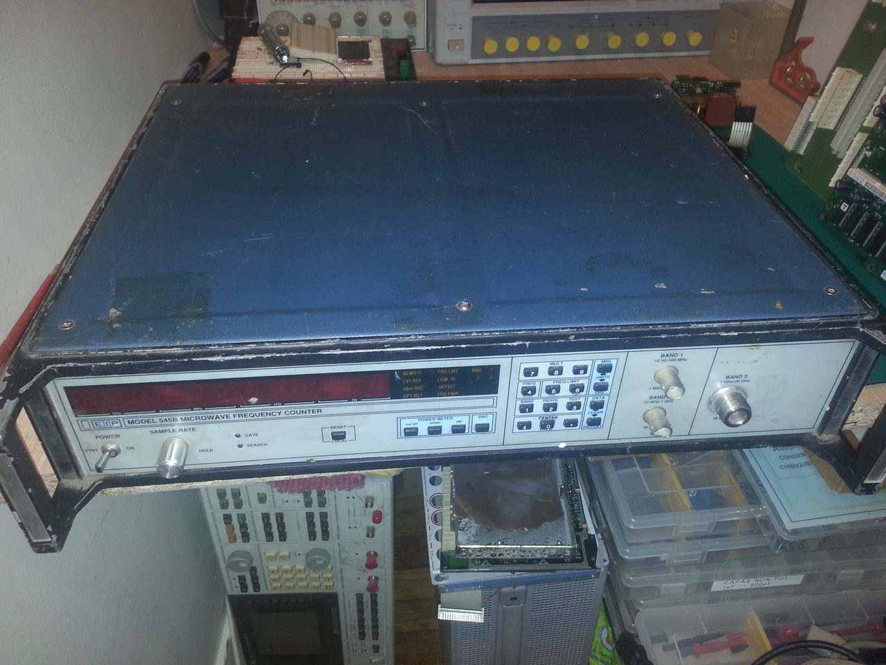
I received a few days ago, and the unit was, as adevrtised, not powering up, but also very dirty, with a bit of rust.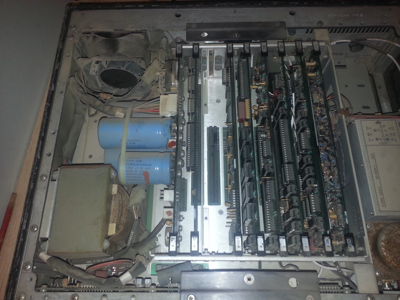
But after a good cleaning, the device seems to work
Now, I'd like to try to modify it to install the Power Meter (Option 2). This has been done by http://www.qsl.net/n/n9zia/vision/ and reproduced several times y SimonDialogs http://www.simonsdialogs.com/2014/09/eip-545a-microwave-counter-power-meter-upgrade/, but only for the 545A model, not the 545B I have.
Both models looks very similar, but not completely, for example, the GPIB board is different: the GPIB address is set via the test number '90' on the B model, whereas on the A model, the "test" 90 is used to configure the YIG calibration curve (it's on test 91 on the B model).
[edit] CPU boards are pretty different also[/edit]
So there are differences in firmwares, which makes me think I won't be able to simply use the EPROM images for the A model.
Has anyone ever tried this procedure on a 545B?
Has anyone have a 545B with option 2 and is willing to dump the EPROMs and make the files available somewhere?
Thanks,
David
PS: for a few more details on the repair of the unit, see my blog post
-
I've been digging a bit this power meter option, and I'm a bit puzzled by the modification made by WB4BPP (aka J. L. Trantham) on http://www.qsl.net/n/n9zia/vision/
Looking at the service manual for both 545A and the 578B (for which the Service Manual is also available and since it has the same CPU board than the 545B, it's probably a better source; the A107 board seems identical on all the versions), I cannot find anything related to the added EPROM on A107.
The differences of the schematics between the version with and without the Power Meter option only consists in the addition of U12 (8bit DAC) and CR3 (Schottky diode) and the removal of the "direct path" resistors R40 and R39 (as described in WB4BPP procedure).
So I wonder what these extra chips are used for (the U19, U20 and U21).
No doubt however that this option 2 must be "activated" somehow in the software, so I still need the main CPU's EPROM content for a 545B with option 2...
David
-
A closer look at these schematics, on the left are 2 tables with the unused references (Ref. Des. Not Used) and the power rails for each chip, and sure enough, U12, U19, U20 and U21 (as well as CR3) are listed as unused on the board without option 2 and added in the power rails in the version with option 2.
So It seems that they are not drawn on the schematic but needed nonetheless...
If I have the courage, I'll reverse ing. this missing part of the schematic, for the sake of understanding :-) -
In fact, in the service manual is this description:Quote
The POWER METER PROM (Option 02 only) contains a logic comparator (U21), a 2K x 8 PROM (U20), and a bus driver (U19).
The logic comparator is connected to the microprocessor address bus, and is configured to decode the 2K address range from 4000 Hex to 47FF Hex.
The comparator output drives the chip select of the PROM and the bus driver.
The PROM contains the Power Meter program as well as the power correction factors.
Bus driver U19 is used as a buffer for driving the microprocessor data bus
so maybe a modified A107 board is enough, without the need for a modified firmware of main CPU board... -
I've been looking a bit at the ROM dumps provided by GBPPR, as well as the EPROM dumps I just made from my unit, and I am pretty sure a modified A107 board will be enough to activate the power meter (no need for extra ROM images on the CPU board).
Also, the instructions they give for the modification talk about the calibration data, but not in details. In fact, the service manual says:QuoteThe power meter contains 690 correction factors. stored in PROM.
The 150 "power vs power" correction factors compensate for variations from
square law in the detector and power meter circuits. They are divided into
three tables. The first table corrects variations below 10 GHz. The second
corrects variations between 10 and 20 GHz. The third corrects variations above
20 GHz.
The 540 "power vs frequency" correction factors compensate for variations in
the detector output at different frequencies. "Power vs frequency" corrections
cover 0-27 GHz every 50 MHz. ' The power meter is calibrated at the factory
using specialized automatic test equipment.
Recalibration in the field is not recommended.
These values are stored at the very beginning of the EPROM. And looking at the calibration data of the unit used to extract the EPROM content for this Option 2 provided on GBPPR, it's clear that it has been calibrated only in the range 0-18GHz since from address 0x1FE, the same value (0x1A) is repeated again and again till the end of this calibration table (0x1FE is 150 (0x96) + 360 (0x168), and 360 because there are 360 50MHz steps in the 0-18GHz range).
I've ordered the parts I am missing to try this mod (probably next year :-) )
-
Has anyone ever tried this procedure on a 545B?
Hi,
54xA Opt.02 circuit doesn't work on 'B' model, the firmware part present in the Opt.02 EPROM is a extension firmware for the 54xA basic firmware and must be the same FW revision.
54xB firmware has already the option parts included, but it is normally disabled, the activation code reside in the CPU card EEPROM memory with the calibration table.
-
Hi,
54xA Opt.02 circuit doesn't work on 'B' model, the firmware part present in the Opt.02 EPROM is a extension firmware for the 54xA basic firmware and must be the same FW revision.
Yes I was a bit worried of such painful incompatibilities.54xB firmware has already the option parts included, but it is normally disabled, the activation code reside in the CPU card EEPROM memory with the calibration table.
Do you have tried yourself? I have not found anything (for now) in the manuals (the ones I could find) that would allow me to guess such a thing. For example, the 575B/578B service manual (ref. 5580032) also mention that "The PROM [on A107] contains the Power Meter program as well as the power correction factors."
Also, the A107 board in both manuals (545A and 575B) is referenced as 2020197-0X (with X from 1 to 8 depending on the combination of 10MHz ref and power measurement capabilities).
I also realized that the service manual for the 545A do explain the calibration procedure of the power meter in details (which the SM of the 575B does not).
David
-
Do you have tried yourself?
No, I have serviced professionally these counters 20 and more years ago.QuoteI have not found anything (for now) in the manuals (the ones I could find) that would allow me to guess such a thing. For example, the 575B/578B service manual (ref. 5580032) also mention that "The PROM [on A107] contains the Power Meter program as well as the power correction factors."
EIP manuals, not the revisited Phase-Matrix ones available, are extremely confusing in the 'A' to 'B' transition, see the CCN number in first page, in case of 545 models this transition was occurred between CCN# 2009 to 2010 and for 548 between 2309 to 2310, BUT the CCN# 2009 545A (2309 548A) is the same hardware as the 54xB (new boards), the old hardware ends with CCN# 2008 (2308).QuoteAlso, the A107 board in both manuals (545A and 575B) is referenced as 2020197-0X (with X from 1 to 8 depending on the combination of 10MHz ref and power measurement capabilities).
A107 board has the same P/N in old and new HW, the suffix change between two version and if Opt.02 is present or not, also for the 10MHz high stability options. Major change was for the CPU board A105 from P/N 2020195-xx to 2020215-xx, and various modification on other boards.
Some years ago I've helped a friend of mine with a 538 counter, my friend was desperately trying to obtain band 3 to work, he has modified the Converter Control board A108 to add the two multi-turn resistive trimmers and relative components missing in respect to old version manual... no joy. I have found that the instrument was an 538B HW with wrong front panel (538A does not exist), previously exchanged by someone
Restored the A108 board removing added components and executed the software calibration with success, sensitivity on band 3 was in specs Quote
QuoteI also realized that the service manual for the 545A do explain the calibration procedure of the power meter in details (which the SM of the 575B does not).
Yes, the procedure is briefly described, but it is not part of standard calibration of these counters, only the manufacturer has the system bench for this power meter calibration.
Years ago I have tried to recalibrate this option on request, with partial success because of insufficient power at 26GHz from the generator.
-
EIP manuals, not the revisited Phase-Matrix ones available, are extremely confusing in the 'A' to 'B' transition, see the CCN number in first page, in case of 545 models this transition was occurred between CCN# 2009 to 2010 and for 548 between 2309 to 2310, BUT the CCN# 2009 545A (2309 548A) is the same hardware as the 54xB (new boards), the old hardware ends with CCN# 2008 (2308).
Sorry, I made a typo, read CCNs for 545x as 2208, 2209, 2210 not as 20xx, for 548x are correct.
Small gift:
http://www.ko4bb.com/getsimple/index.php?id=download&file=EIP_PhaseMatrix/EIP_545_548/EIP_545A_Service_Manual.pdf
This manual is for CCNs 2209/2309, usable for your 545B, CPU board is the new p/n 2020215, some layouts are not updated as the potentiometers on A108, but schematic seems to be correct.
-
No, I have serviced professionally these counters 20 and more years ago.
That's a pretty good reason to have better clues than average Joe :-)Small gift:
http://www.ko4bb.com/getsimple/index.php?id=download&file=EIP_PhaseMatrix/EIP_545_548/EIP_545A_Service_Manual.pdf
This manual is for CCNs 2209/2309, usable for your 545B, CPU board is the new p/n 2020215, some layouts are not updated as the potentiometers on A108, but schematic seems to be correct.
Yes that's one of the manuals I have found (ko4bb is such a bless), I'm also referring to this 57XB one (CCN 1809/2009) in which the CPU board as well as the GPIB board (for example) seems to be exactly the same as the one I have in my unit. I give the example of the GPIB board because with this one, there are no switches to configure the address, this is achieved by 'test 90' config menu (the YIG calibration menu begin 'test 91'), which is what is described in the 57XB manual and matches my unit.
So my assumption is that the 57XB is the same unit as the 54XB one, with the ref loop (A103) and phase lock (A104) boards populated (and probably an adapted firmware).
-
Fun fact: in fact, the power meter is working "out of the box". When I activate it, it display the triple E for a few seconds, then display a power (obviously completely uncalibrated) with a "resolution" of 3dB, since the second AD7526 (U12) is not present.
So I've installed an AD7526 in U12 socket, a FH1100 equivalent diode (a QSCH1245) and removed R39, et voilà! the power meter now works with the 0.1dB resolution!
Now i need to figure out where the calibration curves are stored in the memory. I don't think it's located at the same address as it was on the 545A (0x4000 in the EPROM that can be installed on A107) since the ROM on the CPU board do have content in this 0x4000->0x47FF mem area.
It might even be located in the EEPROM.
I still have a few issues I need to fix:
- I've replaced the CR4 zener diode on A107; it was dead (open), but the sensibility remains too low on band 3 (I can sometimes "catch" a signal at -15dBm or so, but it's unstable). The reference voltages on pin 2 of U14 (LM393 comparator) is now a stable -100mV as described somewhere in the service manual, but the signal detection circuitry is still not working properly. I need to double check the capacitors on this A107 board, since a quick in-place check with a DER DE-5000 LCR meter showed some strange results for some of them (surprisingly, not the tantalum ones, but I'll check theses again with a lead desoldered from the board).
- When I power the device, it's set with a 200MHz offset and only 5 digits of resolution. I guess this is the part of the "SPECIAL WB68" version of the firmware I have, but I find it quite annoying.
- Replace the bent BNC connector for band 2.
- And run a deep check / calibration of the unit.
I've started to (partially) disassemble the firmware to find where I need to change these initial values. Dawn it's been a looong time since I've played with 6800 assembly code! I was also trying to figure out how to activate the power meter, but this is now magically fixed :-)
I'll write a follow up on my blog with the things I've understood in the disassembled firmware when I'm done.
David
-
I still have a few issues I need to fix:
- I've replaced the CR4 zener diode on A107; it was dead (open), but the sensibility remains too low on band 3 (I can sometimes "catch" a signal at -15dBm or so, but it's unstable). The reference voltages on pin 2 of U14 (LM393 comparator) is now a stable -100mV as described somewhere in the service manual, but the signal detection circuitry is still not working properly. I need to double check the capacitors on this A107 board, since a quick in-place check with a DER DE-5000 LCR meter showed some strange results for some of them (surprisingly, not the tantalum ones, but I'll check theses again with a lead desoldered from the board).
Have you checked the calibration on the YIG bandpass filter? If it's out of adjustment, the signal won't get through to the rest of the system or will be badly attenuated. I have a unit that seems to be made of pieces from multiple systems. The YIG filter was about as far out of adjustment as it could be!
Ed
-
Have you checked the calibration on the YIG bandpass filter? If it's out of adjustment, the signal won't get through to the rest of the system or will be badly attenuated. I have a unit that seems to be made of pieces from multiple systems. The YIG filter was about as far out of adjustment as it could be!
Yes I've been thinking something like this may also happen. I'll try to check a bit if the YIG calibration is reasonably OK, at least up to the frequencies I can check for now with the equipment I have.
Ed
David
-
Now i need to figure out where the calibration curves are stored in the memory. I don't think it's located at the same address as it was on the 545A (0x4000 in the EPROM that can be installed on A107) since the ROM on the CPU board do have content in this 0x4000->0x47FF mem area.
It might even be located in the EEPROM.
Just realized HighPrecision wrote a few posts back the PM calibration table is in the EEPROM... doh! Whatever, I still need to find where.
I've found the tests vector table in the firmware, and there is no other (undocumented) test than the ones listed in the service manual (1 up to 11, 90 and 91). Could have been a 92 or any other value to enter a PM calibration menu but it seems no such menu exists... So one have to burn the values in the EEPROM somehow. -
- When I power the device, it's set with a 200MHz offset and only 5 digits of resolution. I guess this is the part of the "SPECIAL WB68" version of the firmware I have, but I find it quite annoying.
Special WB68 is a BAND 3 Low end frequency extension to 0.6GHz (600MHz) with reduced specs for sensitivity and power meter dynamic range.
Frequency offset and resolution setting have not to do with this special option, in the EEPROM there are saved the instrument power-on defaults.Just realized HighPrecision wrote a few posts back the PM calibration table is in the EEPROM... doh! Whatever, I still need to find where.
As I said the power meter calibration is NOT part of the standard calibration procedure, there is no related TEST xx for this.
I've found the tests vector table in the firmware, and there is no other (undocumented) test than the ones listed in the service manual (1 up to 11, 90 and 91). Could have been a 92 or any other value to enter a PM calibration menu but it seems no such menu exists... So one have to burn the values in the EEPROM somehow.
The EEPROM on CPU board is allocated from 0x0800 to 0x0FFF
Power meter calibration table start at 0x0810
YIG DAC calibration table start at 0x0C00, but I have no idea if the special option WB68 start at this location (shifted data ?).
You can use TEST 10 to modify the EEPROM locations, or via GPIB with TA10 command, obviously the write-protect switch should be disabled.
I suggest to save the entire EEPROM before any attempt to change data.
Edit: typos
-
Thanks a lot for all these informations...
0x0810 was on the list of possible "culprits", but I was not near a definitive conclusion yet. Quite a time saver!Special WB68 is a BAND 3 Low end frequency extension to 0.6GHz (600MHz) with reduced specs for sensitivity and power meter dynamic range.
Frequency offset and resolution setting have not to do with this special option, in the EEPROM there are saved the instrument power-on defaults.
I noticed I could go quiter lower the 1GHz on band 3, haven't thought it might be thanks to the WB68 special version.As I said the power meter calibration is NOT part of the standard calibration procedure, there is no related TEST xx for this.
The EEPROM on CPU board is allocated from 0x0800 to 0x0FFF
Power meter calibration table start at 0x0810
YIG DAC calibration table start at 0x0C00, but I have no idea if the special option WB68 start at this location (shifted data ?).
I had these ones from the service manual, yes. And it does not look like the location has moved somewhere else.You can use TEST 10 to modify the EEPROM locations, or via GPIB with TA10 command, obviously the write-protect switch should be disabled.
I suggest to save the entire EEPROM before any attempt to change data.
I already have dumped the whole memory: EPROM + EEPROM (which I will make available on my blog as soon as I have time to write part 2), which is what I've disassembled (the hard part being to locate the constant/data areas... for now, I still have many places where the disassembled code is just garbage due to a CONST area not properly handled).
But no way I enter the calibration values using TEST10! :-)
Another question, maybe I missed this in the service manual, but is there a procedure to check wheter the YIG calibration is correct?
I was thinking about how I can check this (to address my sensibility problem), and I'm not sure what's the best way of doing this verification.
Don't think I can force the YIG to stay centerered at a given freq, without scanning (then inject a know signal and measure the power ouput from A203. Can I? Setting the low/high freq limits to the same value maybe?
David
-
Another question, maybe I missed this in the service manual, but is there a procedure to check wheter the YIG calibration is correct?
I was thinking about how I can check this (to address my sensibility problem), and I'm not sure what's the best way of doing this verification.
Don't think I can force the YIG to stay centerered at a given freq, without scanning (then inject a know signal and measure the power ouput from A203. Can I? Setting the low/high freq limits to the same value maybe?
David
I had to go digging to find it. It's been 5 years since I did this. It's in Section 7 of the manual and it's called "Converter Calibration". My unit started out with a sensitivity of ~ -19 dBm @ 1 GHz. It was so far out of adjustment that the adjustment procedure didn't work. I did more digging and I've got a couple of pages of notes that I can transcribe if necessary. I ended up with a sensitivity that matched the spec of -30 dBm up to at least 11.5 GHz. That's the highest frequency I could generate.
Ed -
Another question, maybe I missed this in the service manual, but is there a procedure to check wheter the YIG calibration is correct?
A quick method only to verify if the YIGF is correctly centered, is to inject a small bipolar current into feedback node of U3 OP-Amp on A108 board, in example: a potentiometer between +12V and -12V, the wiper connected with a reasonable high value resistor in series to the (-) input of Op-Amp. -
A quick method only to verify if the YIGF is correctly centered, is to inject a small bipolar current into feedback node of U3 OP-Amp on A108 board, in example: a potentiometer between +12V and -12V, the wiper connected with a reasonable high value resistor in series to the (-) input of Op-Amp.
Thanks a lot. Pretty obvious once one does look at the schematics of the YIG driver... I'll give a try ASAP.
David -
Thanks a lot. Pretty obvious once one does look at the schematics of the YIG driver... I'll give a try ASAP.
This test is intended to be done in 'search mode' of the counter (no signal detected) for lowest power level to start count, counter firmware execute a fine tune of the YIG filter at first signal acquisition.
Another weak point maybe the YIG current sense resistor (the big one on A108) is out of tolerance.
-
Another weak point maybe the YIG current sense resistor (the big one on A108) is out of tolerance.
Just did a quick check and it's bang on. It would have been too easy :-)
-
Special WB68 is a BAND 3 Low end frequency extension to 0.6GHz (600MHz) with reduced specs for sensitivity and power meter dynamic range.
Frequency offset and resolution setting have not to do with this special option, in the EEPROM there are saved the instrument power-on defaults.
After digging more in the disassembly of the firmware, and comparing the RAM content juste after booting the and after having changed these settings, it appears that these default values **are** hardcoded in the firmware. So, special really means special: it's most probably a very specific crafted firmware for a specific customer...
I "dumped" the RAM using TEST10 via GPIB (with a simple python script).
Now, I need to try to 'fix' this firmware, fix my sensitivity problem, and calibrate the device...
-
Informations about WB68 are very scarce, all I have is this:Code: [Select]
WB-68 B3 .6GHZ to 20 GHZThat's all, this option is possible ONLY on 545B and not on a 548B, the extra space for YIG DAC calibration (to 26.5GHz) is used for this low end extension, probably data shift as I said.
600 MHZ to 1 GHZ 0 to -20 dBm
1 GHZ to 20 GHZ +5 to -20 dBm
BCD remote programming (this is a special on a 545B)
GP-IB (option 08)
          instrument configurated with BCD interface. GP-IB board
          and rearpanel cable physically located in unit.
          BCD to GP-IB and vice versa can be done within 15 min.
This probably mean also that the Microwave Convertor is a special version for this WB68 option, my informations on A203 testing are pratically useless. -
Code: [Select]
instrument configurated with BCD interface. GP-IB board
and rearpanel cable physically located in unit.
BCD to GP-IB and vice versa can be done within 15 min.
I was wondering why I have this BCD board in a blank slot with the device, now I know!
-
I've been investigation a bit more this evening the sensibility problem of my 545B. I haven't been able to improve anything injecting a small current on the negative input of the log amplifier driving the YIG.
I've also tried a quick calibration of the YIG, without noticeable effect either.
Then I've passed (again for some of them) the troubleshooting tree from the service manual, and I've found something wrong:
when locked on a (strong enough) signal on band 3, the IF sits at roughly 127.9MHz instead of 125MHz as described in the manual, for which the troubleshooting tree concludes that "VCO or LOCK CIRCUITRY on A108 BAD".
So I've probed most of the passive components on A108 involved in the lock circuitry of the VCO, and every looks OK so far. I've also removed all the chips to clean (with a bit of Deoxit) the DIP sockets. It's probably useless but cannot hurt.
Tomorrow I'll try to probe a bit the several test points of this section of the circuit to see if I can find something strange, but I'm afraid the problem might be in A201 in which I would have preferred not to put my nose...
David -
when locked on a (strong enough) signal on band 3, the IF sits at roughly 127.9MHz instead of 125MHz as described in the manual, for which the troubleshooting tree concludes that "VCO or LOCK CIRCUITRY on A108 BAD".
127 MHz is correct, EIP has changed IF frequency in later A203 revisions, all 'B' models are 127 MHz.
You can look at the A203 internal IF amplifier, if I remember correctly at right side looking from front, sometimes I've found some leaking SMD ceramic capacitors. Please DO NOT touch the small wires coming from YIG filter through a hole, these are folded as a kind of inductance during factory calibration.
Check also if the screws holding the YIG filter to A203 box are tighten, sometimes loss of performance happen for these loose screws. -
127 MHz is correct, EIP has changed IF frequency in later A203 revisions, all 'B' models are 127 MHz.
Ghezz, thanks you so much.You can look at the A203 internal IF amplifier, if I remember correctly at right side looking from front, sometimes I've found some leaking SMD ceramic capacitors. Please DO NOT touch the small wires coming from YIG filter through a hole, these are folded as a kind of inductance during factory calibration.
Ok I'll be extra careful! How leaky are we talking about there? like they begin to behave like a resistor on DC? Is probing with an LCR meter is enough to detect them (like the DER DE-5000 I have)?Check also if the screws holding the YIG filter to A203 box are tighten, sometimes loss of performance happen for these loose screws.
I'll give the YIG filter a look too. In fact I've opened the YIG to be able to clean it (enclosure was really rusty, as can been seen on the pictures I posted at the beginning of the thread), so maybe there is some "alignment" that must be taken care of when putting is back together. However, it did have poor sensibility before being taken apart, so...
[mode miracle]Don't you have a copy of the 545B service manual somewhere? It would be so much easier! [/mode miracle]
-
I've opened A201 to make a quick check of capacitors in there, nothing stroke my eye.
But I've also disassembled the YIG filter, and I may have found the reason it works poorly on band 3... and it's probably not a very good news.
I've looked at the YIG spheres (since there are 2 of them in this filter) using my cheap USB microscope.
Top side:
And the bottom side (with copper shim removed):
For which a closer look gives:
on which you may see the problem, more visible on this one:
It's not attached to the "holding rod" any more. Luckily, the cage is small enough for the sphere not to fall, but it not seated at it's correct position either...
Should I try to stick it back to the holder? With what kind of "glue"? For the record, these 2 balls are very small, maybe 2 or 3/10 mm, so it will not be an easy task...
David
-
And in the (probable) case I do not succeed in fixing this YIG filter, any idea what is the "meaning" of the '-09 REVA' on my unit (part number is 2010241-09 REVA)?
There are a few of the on eb, but none have exactly the same part number. For example there is a reasonably cheap 2010241-08 Rev. D available, is there a chance it will work (after recalibration)?
David
-
There are a few of the on eb, but none have exactly the same part number. For example there is a reasonably cheap 2010241-08 Rev. D available, is there a chance it will work (after recalibration)?
"-08" is for 5x8B (26.5 GHz) models, odd numbers are for 20GHz ones, 'B' models start with "-05" (127MHz IF), my informations are too old, I suppose that the "-07" is also for 'B' 20GHz... no idea for Special WB-68 of your unit.Should I try to stick it back to the holder? With what kind of "glue"? For the record, these 2 balls are very small, maybe 2 or 3/10 mm, so it will not be an easy task...
Sorry, I haven't tried any repair at this level, normally the entire A203 converter has to be returned to factory for exchange, in few cases I have repaired the manageable areas, only in one case I have success in repair the MW fllter for a short of COMB drive signal to ground, purely a mechanical issue
If you have the possibility to measure the input RL (VSWR) setting the YIG coil current for a specific tune frequency, you can determine if the coupling between input RF link (that is critical) and the YIG sphere is compromised or not.Ok I'll be extra careful! How leaky are we talking about there? like they begin to behave like a resistor on DC?
Yes, DC leak that affect BIAS of amplifiers stages.Quote[mode miracle]Don't you have a copy of the 545B service manual somewhere? It would be so much easier! [/mode miracle]
I have some in paper form, unfortunately NOT in pdf, another member has already asked me for a manual, at the moment don't have much time to do long and tedious scanning sessions...
-
If you have the possibility to measure the input RL (VSWR) setting the YIG coil current for a specific tune frequency, you can determine if the coupling between input RF link (that is critical) and the YIG sphere is compromised or not.
I do have a spectrum analyzer (Advantest R3465, 8GHz) but no TG (well I do have an R3561L that can be used as TG for the R3465 up to 2GHz, but it also needs repair, the output level jumping all over the place). So I may be able to do some measurement "by hand" (sweeping my RF gen), but not completely sure how to do such a measurement properly (I am mostly a newbie in RF).
What is the best way of setting the YIG current to match a given frequency (bypassing the automatic search mechanism)? I don't see any TEST mode for that. Could the min/max frequency parameters be used to achieve this?I have some in paper form, unfortunately NOT in pdf, another member has already asked me for a manual, at the moment don't have much time to do long and tedious scanning sessions...
oh please! please! please! :-) eg. a few pages at a time. Another solution: send it to me, I do the scanning then I send it back.
David -
Humm this is gone to be pretty tricky I'm afraid. According to these docs:
http://www.microlambdawireless.com/uploads/files/pdfs/ytfdefinitions2.pdf
http://www.microlambdawireless.com/uploads/files/pdfs/ytodefinitions2.pdfQuoteThe YIG sphere is typically mounted on the end of a thermally conductive rod (normally beryllium).
This is done for two reasons: 1) the rod acts as a “tuning stick” for orienting the YIG sphere in the resonant circuit and
2) YIG has best performance when it’s temperature is kept constant.
So (obviously) the YIG sphere must be oriented correctly...
When I look at it under the microscope, I can see the rod's mark on the YIG sphere, so in theory, it may be possible to put it back roughly at its original position/orientation.
This will really be tricky... especially since my cheap USB microscope needs to be really close to the observed device to have high enough magnification, so I won't have a clear path to the YIG sphere... I'll try to move the sphere under microscope with a tiny plastic tip ASAP, just to see if it's actually practicable.
Note that the document describing the principles of a YIG filter do describe a single stage bandpass filter as well as a two-stages band-reject filter, using 2 YIG spheres 'in series'. The topology in the EIP input stage seems to be a 2-stages bandpass filter: each YIG resonator is mounted as a bandpass, with the input and output coupling loops aligned at 90°; both filters being in series (the output of the first one, the one that took off the rod in my device, is the input of the second one, via the wire used as coupling loop over both of them).
-
What is the best way of setting the YIG current to match a given frequency (bypassing the automatic search mechanism)? I don't see any TEST mode for that. Could the min/max frequency parameters be used to achieve this?
I cannot test this right now since the YIG is disassembled on my bench, but I think this is achievable but using TEST10 (memory read/write). According to the SM, it seems possible to directly write into the YIG frequency controller (at addresses 0x1840 and 0x1842); for a desired frequency F (in MHz), just have to write F/2 as hex value in these registers.
For example, if I want to tune the YIG filter to 1200MHz, F/2 is 600, ie. 0x0258 in hex.
So I would have to write:- 0x02 at address 0x1842 and
- 0x58 at 0x1840.
-
but using TEST10 (memory read/write). According to the SM, it seems possible to directly write into the YIG frequency controller (at addresses 0x1840 and 0x1842); for a desired frequency F (in MHz), just have to write F/2 as hex value in these registers.
Yes, the addresses are correct for your new CPU board (old version is 0x984x).
These TEST10 commands are to be inserted just after power up of unit (switch OFF and then ON). -
A quick follow up:
- I've been able to fix the -160MHz offset default setting
- I've been able to partially fix the 5 digits resolution default setting
- I've not yet been able to fix the sensitivity problem
For the default settings, I just replaced a few instructions in the initialization routine by NOPs, as described in https://whatever.sdfa3.org/eip-545b-rf-frequency-counter-part-4.html
The problem with the resolution is that I do have all the digits displayed, but the actual resolution remains on 5 digits; I guess there is also some initialization code that configure the gate generator (A107) to modify accordingly...
For the sensitivity problem, I've not been able to put the YIG sphere in place: it is very hard to manipulate by hand. However, I a wondering if this is the only problem; I also suspect the 15dB boost in A201 to be faulty.
I've picked up the schematic of the A201 board (the IF amplifier/detector part):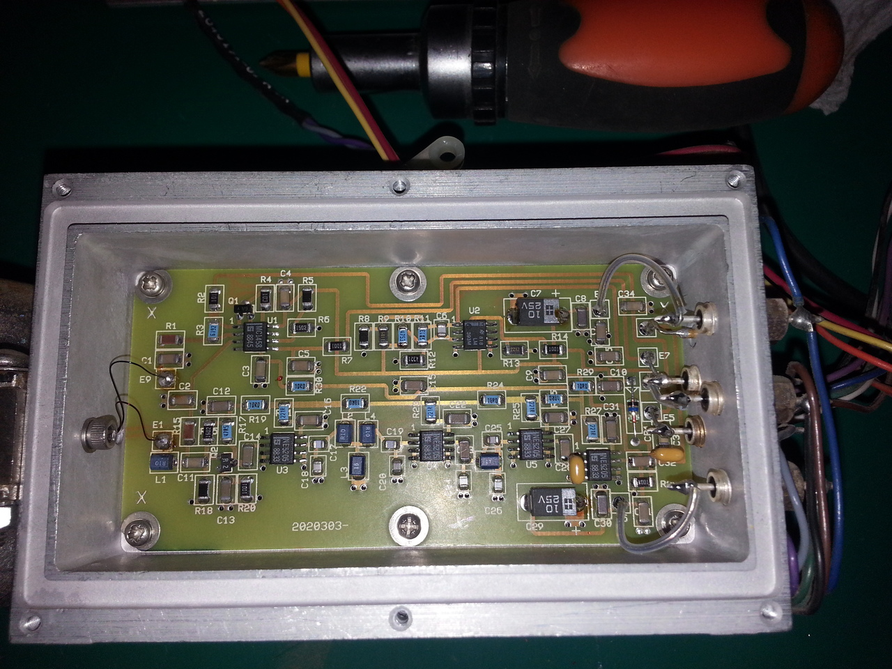

I've been suspecting the Q1 transistor, but I've been fooled by the fact it's a JFET, so it does measure low resistance between the source and the drain when the gate is not high.
I've desoldered it from the board, but it looks to work just fine (cheked with 20$ LCR/transistor meter).
On this schematics, I'm not sure what kind of signal is expected on input E9 (from the YIG): when measuring with a multimeter, I have very low resistance to the ground (maybe 0.2 or 0.3 ohm).
Looking at the output of the YIG, this E9 being the green wire, it looks to be, indeed, connected to the ground on the ceramic board: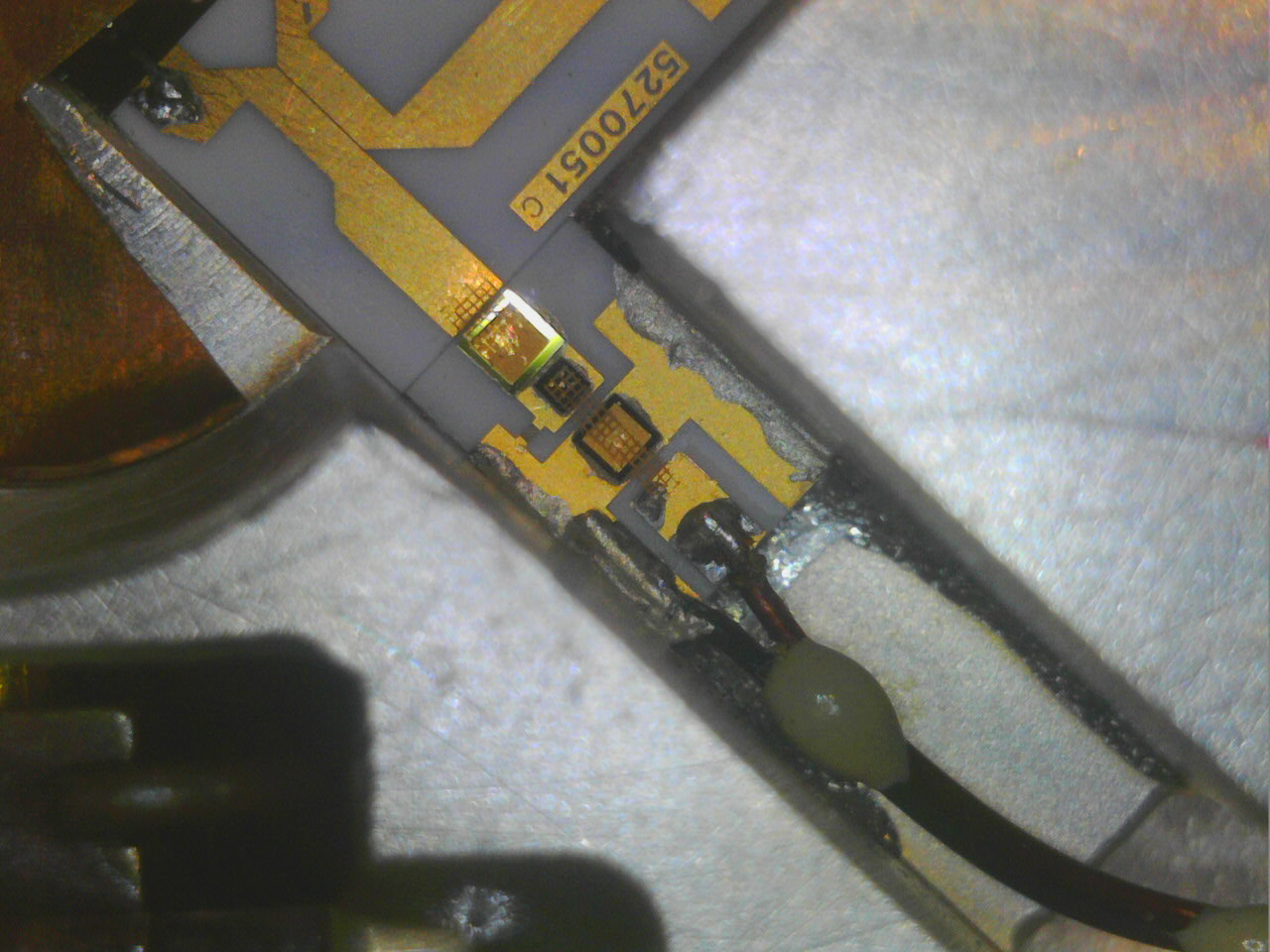
So I guess it should be considered as ground-level (once again, being a noob in RF, I've been fooled by the presence of R1/C1 there (especially R1), as both side of the wire are grounded, but as usual with RF, it's a "transmission line", not an equipotential, so I guess they make sense).
[edit]in fact, when Q1 is blocked, the gain of this amplifier is something like 32 (1+61.9/2), and when the Q1 is on, the gain drops to around 1, so the ~15dB boost controlled by the E7 input.[/edit]
So I need to dig more...
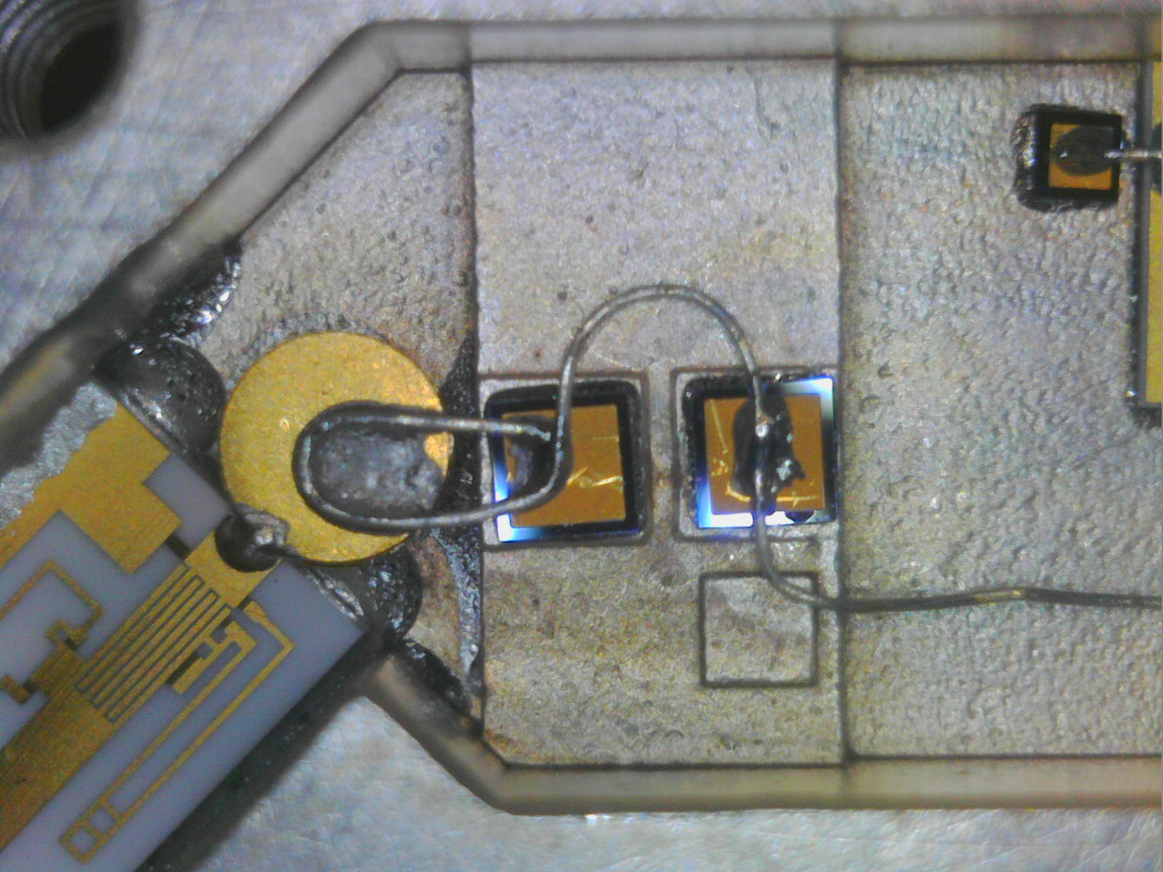
For those playing at home (as Dave would say), here is a picture of the whole ceramic board in the YIG enclosure, including the mixer (the IF signal generated by the VCO arrives on the pin at the top of the picture) :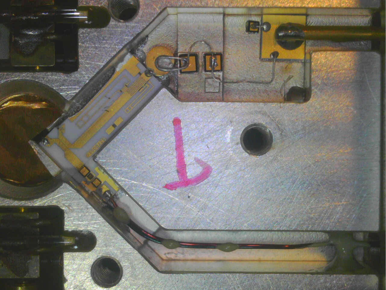
David
-
Hi everyone,
I'm still fighting against this sensitivity problem, and I have hard time understanding how the so called "Video Amplifier" (should) works.
In fact, I'm not sure I do understand the kind of signal and impedance I should expect from the YIG filter assembly. This unit do combine the filter itself (which is known to be partly broken in my unit, as shown earlier), but I'd like to understand a bit better the mixer part.
The mixer looks like the last picture from my previous post.
As far as I understand dit, it consists in two parts:
- the LO path, where there are filtering made of capacitors and inductances (the wire between capacitors) before entering the ceramic circuit, on which lies several stripline-like RF filters ending with a (directional?) coupler to the output signal from the YIG filter itself
- a mixer path, after this coupler, consisting in a few components mounted on the ceramic substract.
My hypothesis is that among these components is a mixer diode (my guess is that this is the first one after the coupler, followed by an LC filter), forming a single diode balanced mixer. Otherwise, I don't understand how this assembly can implement a mixer (since a non-linear device like a diode is required to build a mixer).
Are these assumptions looks right? Any RF guru around there to explain a bit more this mixer/coupler device?
David
-
The programmable VCO signal (370-500MHz) need to be raised in power to have sufficient level to drive the SRD (Step-Recovery Diode), to obtain a wide comb of carriers (multiplies of VCO carrier), after this there is another circuit with the microwave mixer.
In some occasions, the old variant of A203 MW converter (2010137-xx) may have problems with two trimmer capacitors around the VCO power amplifier, turning these usually resumes SRD RF drive power level and consequently the sensitivity of counter. -
The programmable VCO signal (370-500MHz) need to be raised in power to have sufficient level to drive the SRD (Step-Recovery Diode), to obtain a wide comb of carriers (multiplies of VCO carrier), after this there is another circuit with the microwave mixer.
Where is this SRD located? on the A201-A (VCO) board or in the A203 YIG assembly itself (on the ceramic board embedded in the YIG filter assembly)?
BTW, on my unit, the big black resistor near the output 2SC2283 power transistor, can turn very hot, around 150°C; not sure it is expected or a sign of leakage somewhere. The resistor does not seem to suffer, however, from this (it looks physically and electrically OK).
Also, am I correct assuming this ceramic board (the output stage, after the coupler from A201-A, and before entering the A201-B amplifier/detector board for which I did reverse engineer the schematics) includes at least one mixer diode?In some occasions, the old variant of A203 MW converter (2010137-xx) may have problems with two trimmer capacitors around the VCO power amplifier, turning these usually resumes SRD RF drive power level and consequently the sensitivity of counter.
Humm I'm not sure I'm ready to tweak these, not without a better understanding of how this whole unit works and how to probe it when doing adjustments...
-
Where is this SRD located? on the A201-A (VCO) board or in the A203 YIG assembly itself (on the ceramic board embedded in the YIG filter assembly)?
The SRD is obviuosly part of the microwave circuit, I assume is located on LO side of ceramic microcircuit at opposite side of directional coupler, I barely see, on your photo, a complex microwave circuit with inductances, stubs, capacitors, the SRD diode is located here.
Coupling side of the coupler receive the comb signal from LO and is terminated at ground side with a resistor, probably 50 ohm and a laser trimmed capacitor.
LO signal is directionally injected to main side of coupler toward the mixer diode, also on this main side of coupler pass the YIG filtered input signal to mixer.
Just after the mixer there are two small wires for IF output signal (127MHz).QuoteBTW, on my unit, the big black resistor near the output 2SC2283 power transistor, can turn very hot, around 150°C; not sure it is expected or a sign of leakage somewhere. The resistor does not seem to suffer, however, from this (it looks physically and electrically OK).
This resistor is connected in series with a inductance to the RF power transistor collector terminal to feed supply current from the +12V power rail, heating of resistor is NOT normal at 150 degrees level, measure the voltage drop on resistor and the resistance value, it should be 10 ohm.
Try to short the base terminal of 2SC2283 to ground and verify if the voltage drop on resistor goes to zero volts, shorting base to ground removes BIAS voltage from resistive divider, if the voltage drop on resistor remains high the RF transistor is probably damaged.
-
Since I have very little hope in the possibility to really fix my YIG filter, I've been looking for a replacement unit (mainly on eb), and found a cheap one a couple of weeks ago, which I have received last week. It was a bit of a gamble since this (hopefully) replacement A203 is not the exact same part number as mine, but I paid 50$ delivered (and shipment was more expensive than the unit itself), so I took the risk. The unit is clean and in pretty condition:
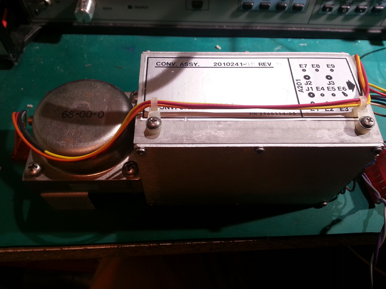
As I said, it is not the same part number as the one I have (2010241-08 vs. 2010241-09 in my unit), however, this replacement unit seems to work fine, and now, the sensitivity is way better than before: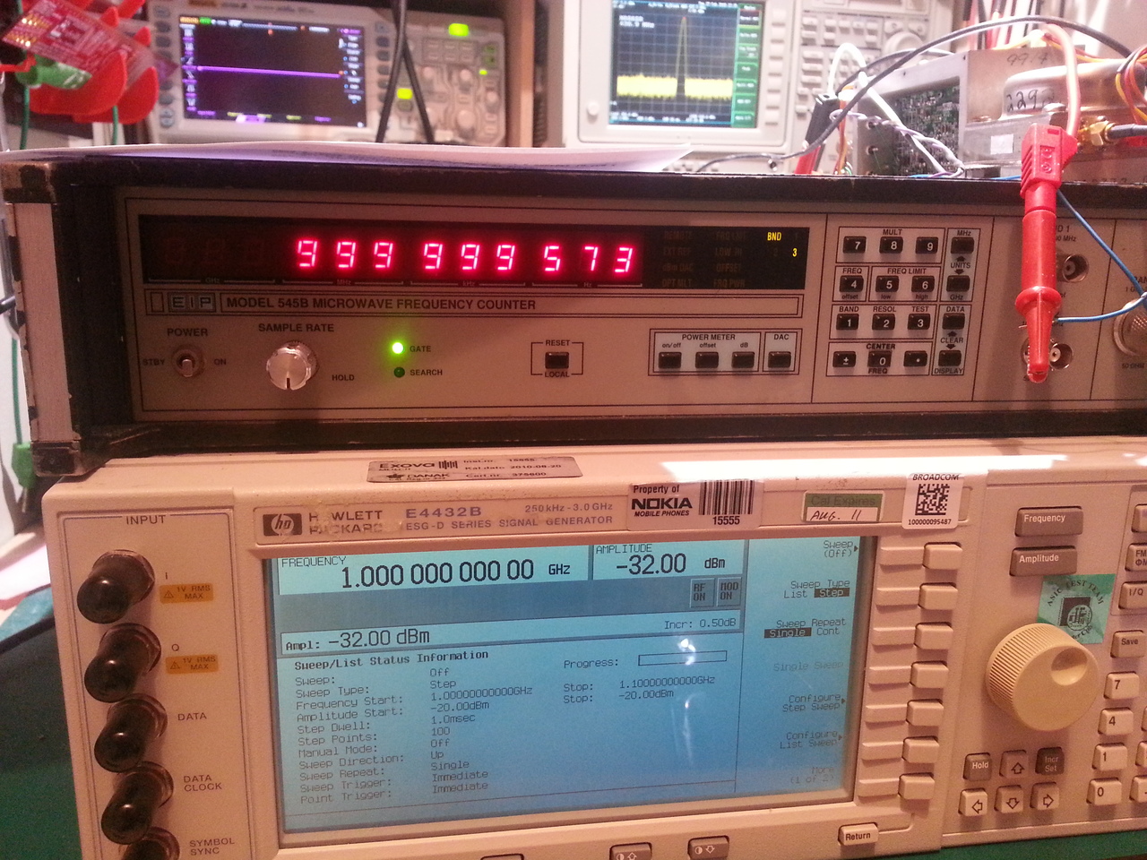
Note that this later picture has been taken without doing any king of calibration of the YIG fiter...
But, as I am a bit stubborn, I still want to investigate more what's wrong with my A203 unit, and thus better understand how it works.The SRD is obviuosly part of the microwave circuit, I assume is located on LO side of ceramic microcircuit at opposite side of directional coupler, I barely see, on your photo, a complex microwave circuit with inductances, stubs, capacitors, the SRD diode is located here.
Nothing is obvious for me :-) I find hard to recognize the components on the ceramic microcircuit, so I'm sure of nothing.
For the pleasure, here are closer views of the ceramic microcircuit (between the VCO output and the directional coupler):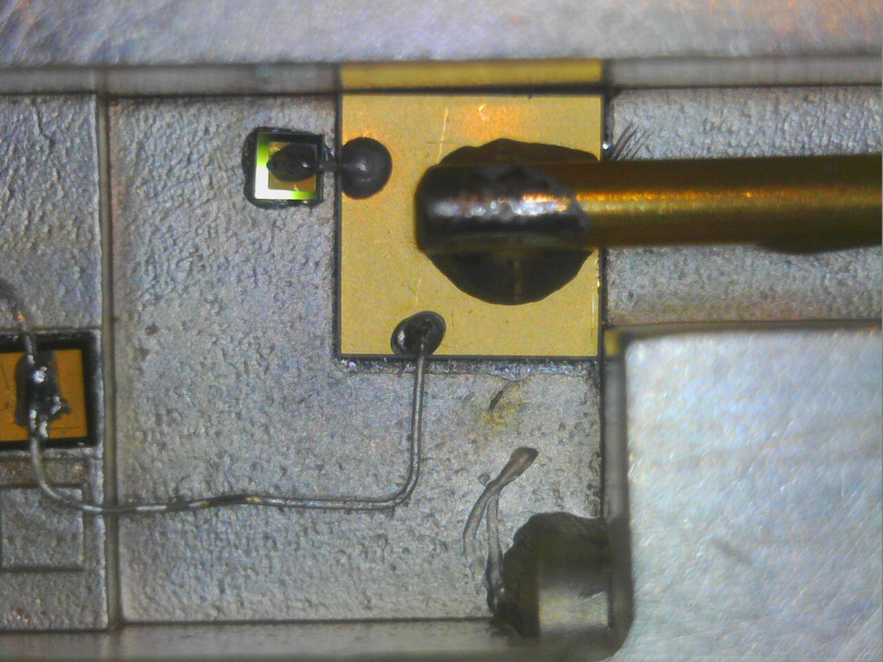
Coupling side of the coupler receive the comb signal from LO and is terminated at ground side with a resistor, probably 50 ohm and a laser trimmed capacitor.
LO signal is directionally injected to main side of coupler toward the mixer diode, also on this main side of coupler pass the YIG filtered input signal to mixer.
Just after the mixer there are two small wires for IF output signal (127MHz).
Yes all these makes much more sense for me now. I may try to draw a schematic of this microcircuit, just for the sake of completeness...This resistor is connected in series with a inductance to the RF power transistor collector terminal to feed supply current from the +12V power rail, heating of resistor is NOT normal at 150 degrees level, measure the voltage drop on resistor and the resistance value, it should be 10 ohm.
Try to short the base terminal of 2SC2283 to ground and verify if the voltage drop on resistor goes to zero volts, shorting base to ground removes BIAS voltage from resistive divider, if the voltage drop on resistor remains high the RF transistor is probably damaged.
Yes it is a 10 ohm resistor. I'll measure the voltage across it tomorrow (or so), playing with the amp power "switch" (via I/O at address 0x1843), and I'll tweak the base term of the 2SC2283 also, and check again the max temperature it reaches (I did measure with my poor's man thermal camera, not very accurate, but very handy when fixing PCBs nonetheless).
And I still have a few tasks to do:
- calibrate the YIG filter (but I can only reach 3GHz with my E4432B),
- calibrate the power meter (which will be way easier now that I have a decent (Gigatronic) power meter with a probe that goes up to 20GHz,
- finish fixing the firmware for the digits resolution default setting (as well as the 'Offset' led indicator that remains on even if I did fix the actual frequency offset value at startup).
David
-
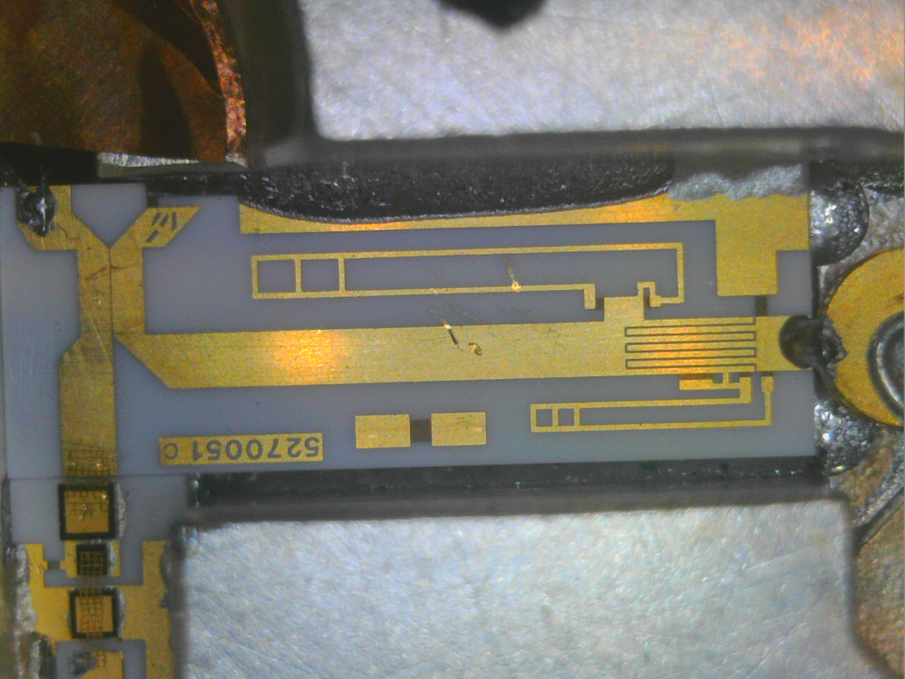
I have removed the VCO board of my broken unit and begun to reverse engineer the schematic (not yet entered in kicad however).
The board looks like this: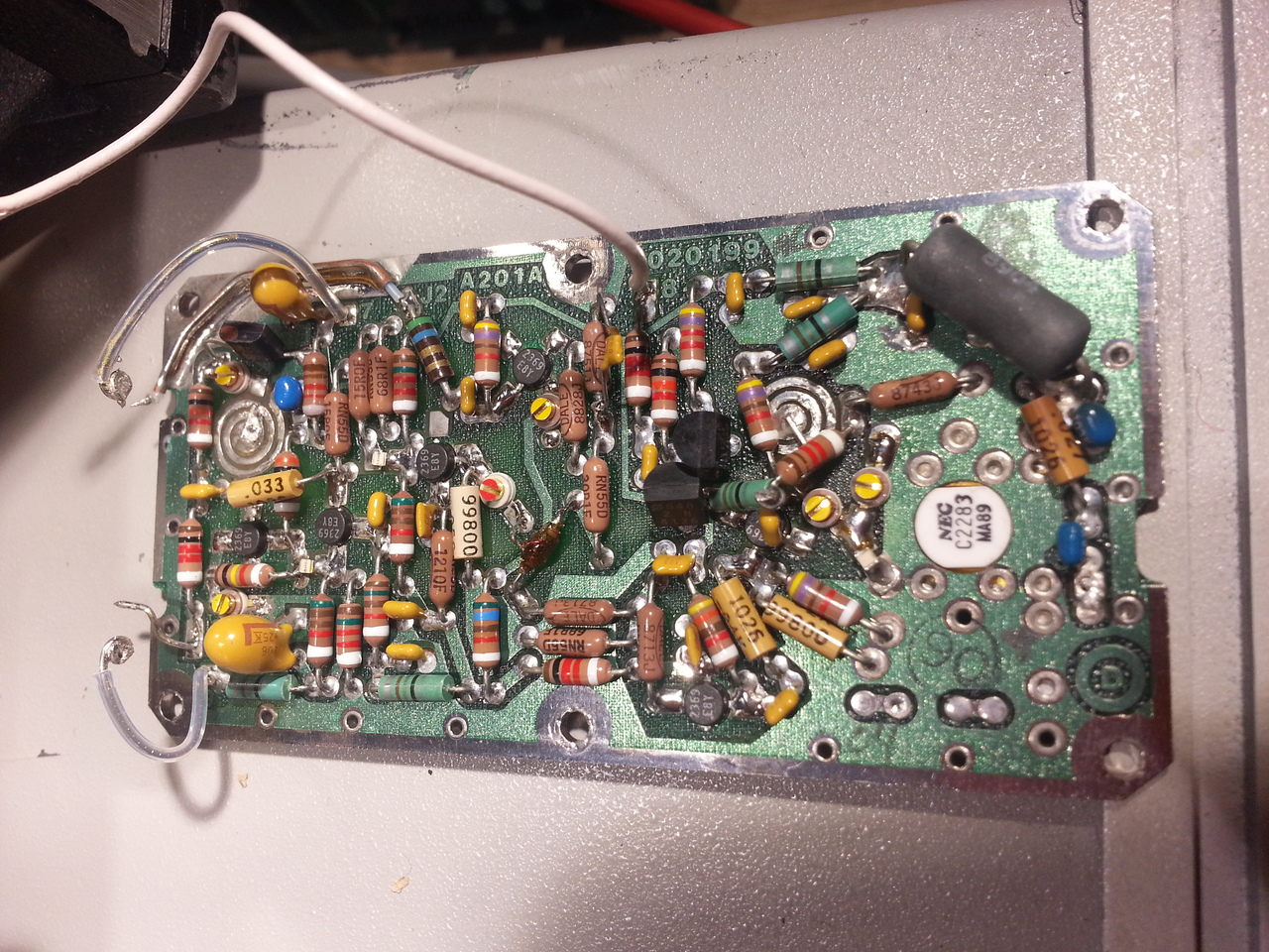
I have not found any obvious culprit for now for its poor behavior (the output transistor, SC2283, looks OK with a simple diode measurement), but I have found an interesting thing:
on this version of the VCO, the big 3W resistor is a Dale RW69 V220: a military version, 22ohm, capable of holding 350°C according to the datasheets!
So it might be normal it's getting pretty hot when the output power amplifier is on.
David
-
SRD harmonic generator is in the blue ring
-
Hi Everybody,
Thanks Douarda for this passionating dive into EIP545B!
I'm also interested with activating the power meter in mine but I don't know how to proceed. When I'm trying to turn on the power meter it says 'Error 13' which I believe means the option is not installed?
However I'm facing to a more serious error since this morning as my counter is saying Error 40 at every startup now and can't count above 1Ghz on Band 3. This suddenly happened. I did all the check on A107 but I've found nothing wrong. The only wrong thing I've found is there is no ramp on J7 pin 2 while this one is there when I'm entering in Test 06.
Does anybody knows what Error 40 is? Sometime when I turn it on ti says Error 32 but right after it switch to Error 40. If I understood correctly Error 32 is related to PROM check (U12?) but I don't know what Error 40 is. Any help will be really appreciated
Thanks! -
douardda, Did you get the YIG working in your counter? If not, I have a 545 that I got in pieces and I have an extra YIG oscillator and it appears to be in good condition. I think it may have option2 in it as well.
-
Hi All,
I've had a look at EIP 575 Service Manual and found Error 40 code means DAC table Error. Thus, if this Service Manual can be used for my 545B I'll be able to repair it. At least I have to dig a bit more onto A107 board now.
Cheers -
I've had a look at EIP 575 Service Manual and found Error 40 code means DAC table Error.
"DAC Table Error" is apparently an access problem to calibration data stored in A105 EEPROM, Error 32 is also suspicious related. Check all power supply voltages on main board, not directly on power supply board, often there are problem on connectors contacts to board edges.
Also check for possible data/address BUS overloads from PIA chips (68B21).QuoteThus, if this Service Manual can be used for my 545B I'll be able to repair it. At least I have to dig a bit more onto A107 board now.
Yes, this manual is usable. -
douardda, Did you get the YIG working in your counter? If not, I have a 545 that I got in pieces and I have an extra YIG oscillator and it appears to be in good condition. I think it may have option2 in it as well.
Hi, yes I have the power meter working. I made some hardware modification on A107: add an AD7524 (U12) , removed R39 and installed a detection diode (I used a QSCH1245 instead of the original FH1100).
But I did nothing on the firmware side: the power meter code was already included in the CPU main EPROMs.
I have not yet made the required calibration for the power meter to be really usable. For now I'm installing a better OXCO in the EIP before doing a complete calibration of the unit (up to rather low frequencies for now, since I cannot generate signals above 3GHz).
Note: I described this in part 2 of my series on my 545B https://whatever.sdfa3.org/eip-545b-rf-frequency-counter-part-2.html
David -
douardda, Did you get the YIG working in your counter? If not, I have a 545 that I got in pieces and I have an extra YIG oscillator and it appears to be in good condition. I think it may have option2 in it as well.
Nope I could not make it work properly. I'm pretty sure I have a problem on one of the 2 boards in this unit (in addition to the loose YIG sphere) so in the meantime, when I found a replacement A201 unit at decent price on eb, I bought it. So I've put this repair aside for now.
David
-
Hi HighPrecision,
Thanks a lot for those precious information! I'll let you know how it goes!
Thanks also David for the information about the power meter. On mine the option is not included, but I would say I have more urgent things to do on this equipment now. -
douardda, Did you get the YIG working in your counter? If not, I have a 545 that I got in pieces and I have an extra YIG oscillator and it appears to be in good condition. I think it may have option2 in it as well.
Hi, yes I have the power meter working. I made some hardware modification on A107: add an AD7524 (U12) , removed R39 and installed a detection diode (I used a QSCH1245 instead of the original FH1100).
Hi Douardda, I was just wondering if you've removed R40 as well? Indeed, according to the schematic of Option 02, the resistor is removed as well.
-
I've had a look at EIP 575 Service Manual and found Error 40 code means DAC table Error.
"DAC Table Error" is apparently an access problem to calibration data stored in A105 EEPROM, Error 32 is also suspicious related. Check all power supply voltages on main board, not directly on power supply board, often there are problem on connectors contacts to board edges.
Also check for possible data/address BUS overloads from PIA chips (68B21).QuoteThus, if this Service Manual can be used for my 545B I'll be able to repair it. At least I have to dig a bit more onto A107 board now.
Yes, this manual is usable.
Hi HighPrecision,
I've not been able to find anything wrong so far. Thus I did like Douardda and I've made a Dump of the EEPROM (from address 0x0800 to 0x0FFF) which took me around 20 minutes to download all the 2048 words thanks to his idea. Then I've had a look at data from 0x0C00 and they don't look right. At least up to 1Ghz (0x01F4) the data look ok but above I'm not sure:
0x0C00, 0x00
0x0C01, 0x08
0x0C02, 0x00
0x0C03, 0x00
0x0C04, 0x01
0x0C05, 0x2C
0x0C06, 0x01
0x0C07, 0x28
0x0C08, 0x01
0x0C09, 0xF4
0x0C0A, 0x01
0x0C0B, 0xF3
0x0C0C, 0x0C
0x0C0D, 0xB2
0x0C0E, 0x0C
0x0C0F, 0xD5
0x0C10, 0xFF
0x0C11, 0xFF
0x0C12, 0xFF
0x0C13, 0xFF
Indeed, if I've understood correctly the data I've dumped, the DAC is tuned at 600Mhz, 1Ghz, and 6.5Ghz, which looks weird and not in line with the Service Manual which is asking for 1Ghz, 1.3Ghz, 10Ghz and 20Ghz. Still it doesn't explain why my counter is not able to count above 1Ghz anymore as it should have done interpolation at least up to 6.5Ghz...
Any thoughts?
Thanks a lot! -
Hi Guile,
DAC Table is clearly incomplete, looks as a aborted TEST 90 calibration process, missing the DEF-2 bytes before 'Table End'.
If you have the required generator do a complete recalibration via TEST 90 as described on 575B manual, at 20 GHz point there is an error, with generator @ 20GHz the frequency inserted is 18 GHz, that is wrong, must be the same frequency of the generator.
If you are unable to do the complete calibration, try to modify EEPROM locations from 0x0C10 as:3F FF 3F FF FF FF FF FF
Also the 600MHz is not a standard cal point for plain 545B without special options. -
Sorry, I'm a bit late to this party.
I've got an EIP 575 which I'm planning to implement the power meter on, I've all the parts, just no time.. sigh..
I thought for future reference I'd add a link to the python script I wrote to use the TEST 10 process over GPIB to read out EPROMs. I was verifying my images matches the "Rev D" set available online. This can be adapted to read out what ever memory range you want.
https://github.com/AshleyRoll/GBIPLogger/blob/master/eip575_memory_reader.py
Note that I'm using a Prologix Etherent GPIB device, but you can modify the code or add drivers as needed to my hacked up code DM me if you need help.
Hope it helps someone.
Ash. -
Hi Guile,
DAC Table is clearly incomplete, looks as a aborted TEST 90 calibration process, missing the DEF-2 bytes before 'Table End'.
If you have the required generator do a complete recalibration via TEST 90 as described on 575B manual, at 20 GHz point there is an error, with generator @ 20GHz the frequency inserted is 18 GHz, that is wrong, must be the same frequency of the generator.
If you are unable to do the complete calibration, try to modify EEPROM locations from 0x0C10 as:3F FF 3F FF FF FF FF FF
Also the 600MHz is not a standard cal point for plain 545B without special options.
Thanks a lot HighPrecision, your tricks worked!! Error 40 is gone and I can hear the tick tick tick of the Band 3 assembly again!! Unfortunately the only source I have goes up to 8Ghz (which is ironic as I've retuned its YTO thanks to my EIP...).
I don't know what has gone wrong as the protection switch was in the protected position (it tooks me a while to understand why I had Error 20 when trying to access to Test 10). Thus I'm affraid that something went wrong and that the whole EEPROM, or a big chunk of it has been erased... I'll try to recalibrate it up to 8Ghz and I'll see if I can rent a 20Ghz source later.
Also I've never tried to run Test 90, but now I know how to proceed.
Thanks again
-
Sorry, I'm a bit late to this party.
I've got an EIP 575 which I'm planning to implement the power meter on, I've all the parts, just no time.. sigh..
I thought for future reference I'd add a link to the python script I wrote to use the TEST 10 process over GPIB to read out EPROMs. I was verifying my images matches the "Rev D" set available online. This can be adapted to read out what ever memory range you want.
https://github.com/AshleyRoll/GBIPLogger/blob/master/eip575_memory_reader.py
Note that I'm using a Prologix Etherent GPIB device, but you can modify the code or add drivers as needed to my hacked up code DM me if you need help.
Hope it helps someone.
Ash.
Thanks for proposing your help Ash, but I've also developed similar script to dump my EEPROM. However if you can share with me your EEPROM content (from 0x0800 to 0x0FFF) I'll be very grateful!!
Now I need to recalibrate my counter again but I'm still interested with activating the Power Meter. Let's try together if you agree
Cheers -
Sorry, I'm a bit late to this party.
I've got an EIP 575 which I'm planning to implement the power meter on, I've all the parts, just no time.. sigh..
...
Thanks for proposing your help Ash, but I've also developed similar script to dump my EEPROM. However if you can share with me your EEPROM content (from 0x0800 to 0x0FFF) I'll be very grateful!!
Now I need to recalibrate my counter again but I'm still interested with activating the Power Meter. Let's try together if you agree
Hi Guile,
I figured you had already done something similar, but I thought I would leave the code here for others in the future
I'll dump our the calibration data for you over the weekend. Hopefully it matches the memory range you expect. Mine is a 575, not a 545B however...
If you haven't seen it, here is another person adding the Option 2 power meter..
http://www.simonsdialogs.com/2014/09/eip-545a-microwave-counter-power-meter-upgrade/
I was planning on documenting and sharing my progress on the upgrade, so more than happy to work this out together
Cheers,
Ash. -
Sorry, I'm a bit late to this party.
I've got an EIP 575 which I'm planning to implement the power meter on, I've all the parts, just no time.. sigh..
...
Thanks for proposing your help Ash, but I've also developed similar script to dump my EEPROM. However if you can share with me your EEPROM content (from 0x0800 to 0x0FFF) I'll be very grateful!!
Now I need to recalibrate my counter again but I'm still interested with activating the Power Meter. Let's try together if you agree
Hi Guile,
I figured you had already done something similar, but I thought I would leave the code here for others in the future
I'll dump our the calibration data for you over the weekend. Hopefully it matches the memory range you expect. Mine is a 575, not a 545B however...
If you haven't seen it, here is another person adding the Option 2 power meter..
http://www.simonsdialogs.com/2014/09/eip-545a-microwave-counter-power-meter-upgrade/
I was planning on documenting and sharing my progress on the upgrade, so more than happy to work this out together
Cheers,
Ash.
Hi Ash,
Sharing your code is a good idea for sure!
I'll be very happy if you can provide me this dump. Indeed I'm planning to repopulate my EEPROM with calibration from other meter and recalibrate it up to 8Ghz for now with the equipment that I have.
Regarding to the power meter, yes Simon is a really nice guy. First I've bought some programmed EEPROM from him but when I had my Error 40 failure and that I had to open my meter I've realized that our CPU board were totally different (shame on me). Thus I've a complete set of programed EEPROM for 548A if someone is interested with (just MP).
This meter is really confusing as both the SM of 545A and 575B manual are describing the same A105 CPU Board that I have (2020215) which is totally different from the one described by Simon and from the picture found in the EEPROM zip file available online.
Thus, regarding to 545B I need to find a way to activate the power meter (removing the Error 13). I'm wondering if computing the correct checksum like indicated by 545A SM would suffice to activate it?
Cheers
Guile -
Thus, regarding to 545B I need to find a way to activate the power meter (removing the Error 13). I'm wondering if computing the correct checksum like indicated by 545A SM would suffice to activate it?
Hi Guile,
For 'B' models, and more confusing for last CCN number of other non-B models, equipped with new A105 CPU card (2MHz clock) it's NOT necessary to calculate the checksum and nor to write related location.
For Opt 02 activation you already know the modifications to A107 board to add missing DAC chip and remove/install components as explained by douardda, yes also the R40 has to be removed.
Give me your data in EEPROM locations from 0x0800 to 0x080F and I'll try to suggest the possible modifications for option activation
-
Thus, regarding to 545B I need to find a way to activate the power meter (removing the Error 13). I'm wondering if computing the correct checksum like indicated by 545A SM would suffice to activate it?
Hi Guile,
For 'B' models, and more confusing for last CCN number of other non-B models, equipped with new A105 CPU card (2MHz clock) it's NOT necessary to calculate the checksum and nor to write related location.
For Opt 02 activation you already know the modifications to A107 board to add missing DAC chip and remove/install components as explained by douardda, yes also the R40 has to be removed.
Give me your data in EEPROM locations from 0x0800 to 0x080F and I'll try to suggest the possible modifications for option activation
HI HighPrecision,
Thanks a lot I think we can consider my EEPROM as blank (as it is filled with 0xFF almost everywhere). I'll MP you my dump tonight when I'll be back home
By the way I've read again this entire thread (and my apologies to Douardda as I didn't want to flood his post with my problems) and it appears that I also have FW Special W98 (or something like that).
Thus recently I started to have the frequency offset (-160kHz) and resolution low activated at startup which I didn't have before. Thus if I understand correctly this information resides also in the EEPROM, am I right? As this problem appeared before Error 40 happened, I'm wondering if this was not an annunciation of a problem with the EEPROM?
Thus if someone with the same CPU board and same FW (and same EP1 545B) could also send me his dump, maybe I'll be able to compare and select the best data to compensate the lost I had in my meter .
.
Finally, going back to my EEPROM dump, you mentioned that 600Mhz calibration was for special options. It looks like this option is related to the FW I have, right? Thus maybe 6.5Ghz is also part of this special calibration?
Thank you!
Guile -
Thanks for proposing your help Ash, but I've also developed similar script to dump my EEPROM. However if you can share with me your EEPROM content (from 0x0800 to 0x0FFF) I'll be very grateful!!
Now I need to recalibrate my counter again but I'm still interested with activating the Power Meter. Let's try together if you agree
Cheers
So, on my unit the entire range between 0x0800 and 0x0FFF is "blank" (0xFF). It doesn't appear to have any non-volatile ram, at least in that range. I guess my entire memory map is different that I have found in the available service manuals..
My EIP 575 has A105 (CPU) board part number 2020195 (-01 hand written) if that helps at all.. probably not..
Maybe HighPrecision can shed some light on the older '575 units?
The model and serial numbers read:
Mod: 575 CCN 1802
SER: 00671
Ash.
-
So, on my unit the entire range between 0x0800 and 0x0FFF is "blank" (0xFF). It doesn't appear to have any non-volatile ram, at least in that range. I guess my entire memory map is different that I have found in the available service manuals..
My EIP 575 has A105 (CPU) board part number 2020195 (-01 hand written) if that helps at all.. probably not..
Maybe HighPrecision can shed some light on the older '575 units?
The model and serial numbers read:
Mod: 575 CCN 1802
Hi Ash,
Between A105 old type (2020195-xx) and new type (2020215-xx) cards the memory and peripherals map is completely different, only the new 2020215 has one (EE)PROM (e2prom) allocated from 0x0800 to 0x0FFF (X2816A 2Kbytes type).
Old cards don't have any non-volatile configuration/calibration storage, only UV Erasable (E)PROM, 2516 or 2532 ancient types, the new card use three 27C128 UV (E)PROM with all option firmwares fitted.
On old card the options are added by additional UV (E)PROMs in related empty sockets as firmware extensions, for Opt.02 (Power Meter) is installed on A107 and contain either calibration table AND the PM firmware, it's important that the firmware is the SAME revision letter as the base firmware on A105 old type. For this reason Simon sells the entire set of (E)PROM (base + PM extension with cal data), obviously that CAL data isn't optimized for all counters, but only for the original calibrated unit.
Your EIP counter is a very early CCN#, this model (18GHz) was started with CCN:1800 in production and got new A105 card at CCN:1808, from CCN:1809 are all 575B models. -
Thanks for proposing your help Ash, but I've also developed similar script to dump my EEPROM. However if you can share with me your EEPROM content (from 0x0800 to 0x0FFF) I'll be very grateful!!
Now I need to recalibrate my counter again but I'm still interested with activating the Power Meter. Let's try together if you agree
Cheers
So, on my unit the entire range between 0x0800 and 0x0FFF is "blank" (0xFF). It doesn't appear to have any non-volatile ram, at least in that range. I guess my entire memory map is different that I have found in the available service manuals..
My EIP 575 has A105 (CPU) board part number 2020195 (-01 hand written) if that helps at all.. probably not..
Maybe HighPrecision can shed some light on the older '575 units?
The model and serial numbers read:
Mod: 575 CCN 1802
SER: 00671
Ash.
Hi Ash,
Thanks to my blank EEPROM your results are really close to mine now Thanks a lot for having tried!
Thus if I understood correctly what HighPrecision said, it looks like that what you have to do is to buy some EEPROM, DAC, and diode and program them with the available files online.
By the way I know now that my model is 545B CCN 2213 and I have option WB68 installed.
Good luck for your modification ! -
My EIP 575 has A105 (CPU) board part number 2020195 (-01 hand written) if that helps at all.. probably not..
Maybe HighPrecision can shed some light on the older '575 units?
Hi Ash,
Between A105 old type (2020195-xx) and new type (2020215-xx) cards the memory and peripherals map is completely different, only the new 2020215 has one (EE)PROM (e2prom) allocated from 0x0800 to 0x0FFF (X2816A 2Kbytes type).
Old cards don't have any non-volatile configuration/calibration storage, only UV Erasable (E)PROM, 2516 or 2532 ancient types, the new card use three 27C128 UV (E)PROM with all option firmwares fitted.
On old card the options are added by additional UV (E)PROMs in related empty sockets as firmware extensions, for Opt.02 (Power Meter) is installed on A107 and contain either calibration table AND the PM firmware, it's important that the firmware is the SAME revision letter as the base firmware on A105 old type. For this reason Simon sells the entire set of (E)PROM (base + PM extension with cal data), obviously that CAL data isn't optimized for all counters, but only for the original calibrated unit.
Your EIP counter is a very early CCN#, this model (18GHz) was started with CCN:1800 in production and got new A105 card at CCN:1808, from CCN:1809 are all 575B models.
HighPrecision, wow, thanks heaps for the details!
I have the full set of "rev D" EPROM images, including the Option 2 EPROM that goes onto the A107 board. I actually verified that my A105 EPROMs all match this set byte-for-byte. So I'm pretty confident I can make the hardware changes and get the power meter option up and running.
I've also got a handle on the calibration process, but that will have to wait until I have some free time and can get to a friend's place to use his power meter and signal generators.. and lug along a PC and EPROM programmer
Do you know of any service documentation that better matches my model?Thanks to my blank EEPROM your results are really close to mine now
Thanks a lot for having tried!
Thus if I understood correctly what HighPrecision said, it looks like that what you have to do is to buy some EEPROM, DAC, and diode and program them with the available files online.
By the way I know now that my model is 545B CCN 2213 and I have option WB68 installed.
Good luck for your modification !
Thanks Guile, Hope you managed to find a way to fix yours as well!
Cheers,
Ash.
-
Thanks Guile, Hope you managed to find a way to fix yours as well!
Cheers,
Ash.
Hi Ash,
Thanks! Indeed, thanks to HighPrecision everything in my counter is back to normal and the Power meter is activated!! :
On the attached picture, I've set my Source output to -23dBm (the minimum it can do) through a 5dB attenuator, and I've read around -28dB with my Power meter, hence the calibration is a bit off but I'll try to fix that in the future.
@HighPrecision: I owe you a beer!! If you're coming in Nice one day let me know I'll fulfill my promise then
Cheers
-
Do you know of any service documentation that better matches my model?
Hi Ash,
best available match is the 545A manual for CCN:2205, all cards, except A103 and A104, are pratically the same part number suffix (revision), I've uploaded here:
https://www.dropbox.com/s/hmu2vq9ew4fcaun/545A-548A_Manual_5580021-04_Apr83%20%28CCNs%202205%20and%202305%29_2nd%20Ed.pdf?dl=0
For A103 and A104 cards please refer to the available 57xB manual. -
@HighPrecision: I owe you a beer!! If you're coming in Nice one day let me know I'll fulfill my promise then
Cheers
Hi Guile,
Good! I'm glad to know that it has completely solved the problems. -
Do you know of any service documentation that better matches my model?
Hi Ash,
best available match is the 545A manual for CCN:2205, all cards, except A103 and A104, are pratically the same part number suffix (revision), I've uploaded here:
https://www.dropbox.com/s/hmu2vq9ew4fcaun/545A-548A_Manual_5580021-04_Apr83%20%28CCNs%202205%20and%202305%29_2nd%20Ed.pdf?dl=0
For A103 and A104 cards please refer to the available 57xB manual.
Awesome, thanks @HighPrecision! That helps a lot.
Now I've just got to find the time to do some playing around with it..
Ash. -
Hi guys,
I'm looking now on how to calibrate the power meter with the limited equipment that I have and then I've tried to read out the calibration data from files available online and also from 548B counter to see how I could interpolate the results over the entire range of the counter.
Thus I've attached the comparison results between 3 devices.
It looks like that a 2nd or 3rd order polynomial calculation could work well for the power level calibration at 2Ghz. However, the Frequency spread looks like more difficult to interpolate. At least I'll try once I'll have time and let you know how it goes.
By the way, at 2Ghz, with the data coming from the 548B counter I have 3dB of offset ; and as indicated by the Frequency chart spread, this offset varies over frequencies...
Cheers
-
Hi Guys,
I'm providing some update regarding to the power meter calibration.
I've decided to use my signal generator with a 20dB attenuator to calibrate the first 150 power values at 2Ghz. Indeed, my power meter is reliable down to -20dBm and it looks like that I need to go down to -40dBm in order to calibrate nicely at 2Ghz. Hence, as my signal generator is able to deliver from +10 to -20dBm I'll use the 20dB attenuator for the lower part with my power meter to confirm that I'm running at the right level before attenuation.
However I'm not able to go above 8Ghz and after 3.8Ghz my power source is no more leveling the signal. Then I can set something around -15dBm with various attenuators, but I'll not be able to calibrate above 8Ghz. That's the reason why I tried first to find a polynomial model to interpolate the calibration values up to 20Ghz, but without a success.
Then I've moved to machine learning with Gradient boosting algorithm and it looks like to give reasonable estimation (I've attached the estimation with different parameters in yellow; the red curve is the prediction based on one EIP545A meter eeprom dump while the blue one is the prediction based on one EIP575A meter eeprom dump. The yellow curve is the prediction combining both). Hence once ready I'll explain more the theory I'll use. But I need first to fix my EIP again as I'm no more able to read a thing from GPIB while writting works partially. Maybe a bus driver is faulty on the A101 board ( )
)
Cheers
-
But I need first to fix my EIP again as I'm no more able to read a thing from GPIB while writting works partially. Maybe a bus driver is faulty on the A101 board (
Hi Guile, )
if the interface don't respond at normal commands probably is a HW fault, BUT if you are not aware of these (E)EPROMs that have a limited number of WRITE cycles, apparently the Xicor type X2816A listed on 575B manual have approximately 500K/cycles estimated from new. -
Hi HighPrecision,
Thanks for your helps!
Right, the interface hardly respond to command and does not send back data when asked. That's weird as it was working great previously. I don't know how many times the EEPROM has been written but for my case I've written the 531 values only once, thus I don't think the EEPROM as suffered from this task (even if I still don't understand why it has wiped some of the YIG calibration data out).
I'll have a look at the A101 board as soon I have time.
Regarding to the calibration interpolation I'm planing to use, I'm more and more considering to calibrate the power level of the counter up to 3.8Ghz and use the interpolation up to 20Ghz. Then, I'll test the other frequencies up to 8Ghz (which is the maximum I can reach with my equipment) to have an idea of my interpolation function error... I'll be able to say if this idea is good or not
Cheers -
I think this is a relevant thread ?
I have an EIP 548A option 02, 06, counter that I have not used for about 15 years.
Today it would not do anything apart from some digits on the LED's. Turned out the 12V line was a dead short on the +12V line on A107. Fixed that (shorted tantalum by the edge connector) and it works at least up to 2.7Ghz (as far as I can generate right now).
However it is stuck on Band 3 and apart from the the offset button that sort of brings up the power meter, none of the other buttons seem to work, including test functions. I would really like the power meter on/of and the band buttons to work ! I seem to remember the band switching was always difficult.
I'm an analogue only engineer but have determined that the keypad is working with row and select going into the relevant chip, but then I'm stuck, any help greatly appreciated.
Thanks
Dave -
While it does sound more like a digital problem, you never know. On my similar EIP 578 counter, there were 15 shorted tantalums!!! Most of them
were the 10 uF jobs. Carefully check ALL the power rails and check for any tantalums that are used for other purposes than filtering the voltages coming
on to the board from the power supply. It shouldn't take much time and you might get lucky. -
All the power supply voltages are good. I'll try all the other tants tomorrow, but see below :
I need to know what comes out where and especially what does the MC68B21 do and what should I see on its outputs ?
Thanks
Dave G4IUG -
Hi,
the manual explains logic of keyboard scan, see A110 and A111 boards section, see also the troubleshooting chapter for keyboard problems.
If the 'Offset' button (Power-Meter Offset ?) is the only responsive button seems that the 'Keyboard Interrupt' circuit is locked by a low level from a single or more 'columns' lines... apparently your 'Offset' switch seems to be stuck closed or is leaking. -
Thanks HP, I'll try that later but we are entertaining Jill's Mum and a Church lady today !
BTW I missed the keyboard test page.
More later
Thanks
Dave -
.
Well, I checked all the Tantalums and they were all just fine, apart from the one I already replaced that had a dead short.
I have cleaned all the interconnect pins between the two boards and with some new pins exercised the sockets with switch cleaner.
So far it is the same as before, displays the correct frequency on Band 3 but unable to switch to any other band or to switch the power meter on, only the power meter offset and a frequency limit switch seems to do anything.
U12 pin 2 the keyboard interrupt stays low until any key is pressed.
U11 the MC68B21P, Figure 111a shows the clock on PA1 pin 3 to be continuous, I cant's see anything there.
Any help greatly appreciated.
Thanks Dave
-
The clock waveform/drawing isn't scaled or accurate in the service manual.
It turned out to be :
I had another look, this time with my elderly but lovely HP Logic Probe. When I probed the 74LS195 pin 10 the clock input, and this chip is the keyboard scanner, it started working and kept working. I had a look and only on that chip nearest the top cover edge, had corroded pins, so I put it in an IC runner/straighter and cleaned one side of all the pins with very fine emery as well as switch cleaning the IC socket that looked OK anyway. It's now stable as a rock, even the limited power meter function works !
So just one tantalum capacitor and a clean of one IC's pins.
Thanks for the help and inspiration here.
Dave -
Sorry for late response, I'm living very sad days in this period, just lost my beloved father

Good, I've suspected the KB row counter U3, well done.
From your first post I expect a 548A model, the PIA 68B21 is present in newer units (548B), based on the new A105 microprocessor board clocked @2MHz, check the A105 if it's a newer board, also installed in 548A CCN# 2309 -
.
.
Very sorry to hear about your father.
Yes, I said it was an "A" when in fact it is a "B", not sure why I said that.
The good news is that now it is perfectly responsive whereas years ago, when it last worked, it was often difficult to drive, maybe the corrosion had already started to set in.
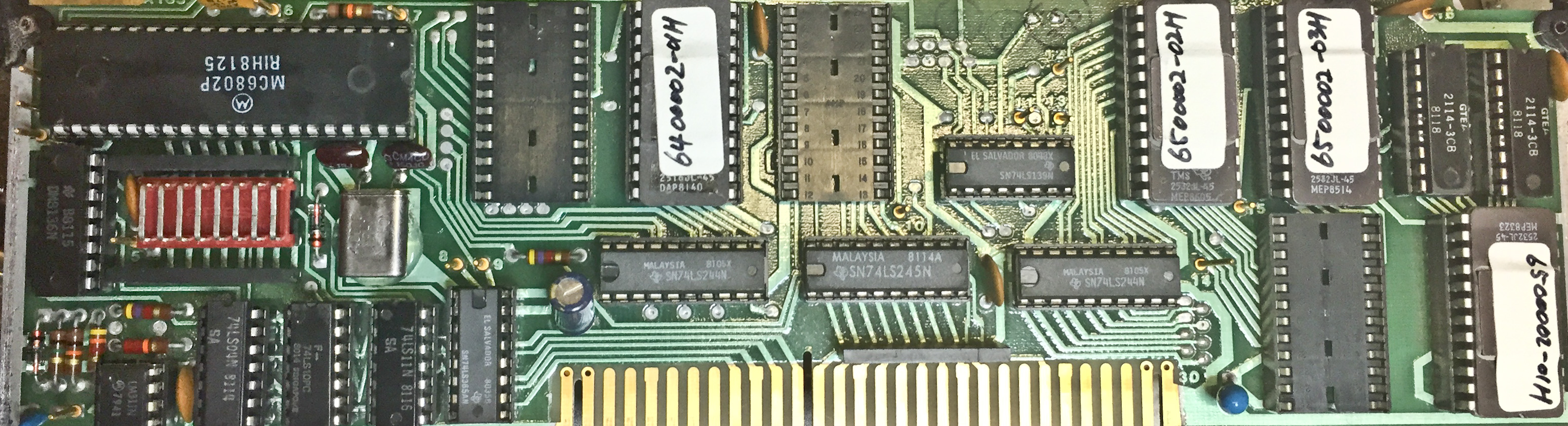
Attached is a photo of the Micro board with 3 chips missing ! But it works and I believe it has never been touched as I know the original purchaser. BTW if you right click and copy the image it is 3K wide.
Regards
Dave
-
This board is the old type @1MHz clock and ancient EPROMs TMS2516/2532, empty sockets are for option firmware extensions, your Opt.02 Power-meter EPROM is located on A107 board.
New board is much different, see this link:
https://911components.myshopify.com/products/eip-micorwave-2020215-02-a-circuit-card-assembly
See my previous posts for more detailed explanations. -
That's odd ? I also have the band 4 option but not the external sensor, but I don't need it.
Do you think my counter may not be as original as I thought it was ?
Whatever, it is doing what I want so I'm a happy bunny !
Regards
Dave -
That's odd ?
Not necessarily
Your hardware configuration depend by CCN number on a label at rear panel, unless this unit was modified previously by others (board exchange), the presence of MC68(B)21P probably indicate a possible previous attempt to resolve the keyboard problem.
I have a 578B with some options (01,02,05,06) and this unit have some old boards, clearly exchanged with other units, but after repair it's fully operative with very good sensitivity on band 3.
-
Just went into the workshop it is a 548A, options 02, 06 serial number 02063 ccn 2309 or maybe 2307 ?
Sensitivity on 2.7Ghz -32dBm -
Just went into the workshop it is a 548A, options 02, 06 serial number 02063 ccn 2309 or maybe 2307 ?
Sensitivity on 2.7Ghz -32dBm
A105 board in your photo is consistent with the CCN 2307
band 3 sensitivity at -32dBm is good as the majority of these units, some A203 MW converters exhibit more sens as mine at -37dBm. -
That's good then. The final thing is that the power meter will only function on Band 3. Dosn't bother me though.
Thanks
Dave -
I am very sorry to open VERY old thread, but....
I have also bought EIP 545B from israel. 2 units. One was not working, the other blew fuse. First unit repaired itself on way to me - probably just bad connection on the interconnect. Second had transformer shortage.
But back on topic. Power meter is not enabled on any of these units and both have that special WB firmware. I put the firmware into Ghidra (there is support for 6805 cpu in git).
After day of digging:
eeprom offsets:
0 - set to 0x00 to enable power meter option
2 - set to 0x5a to enable DAC option
3 and 4 set to 0x35 and 0x59 for some magic (probably band 4 operation, I have not traced this, not sure what it does)
Frequency offsets:
As "douardda" found out, the frequency offset is set in firmware right at the beginning, together with resolution.
Frequency offset can be disabled by removing the code, led will stay light up.
for resolution:
This is the code from douardda's blogCode: [Select]6125 LDX #M005D ;8E 00 5DThere is however very important function called right after.
6128 LDA #$0D ;86 0D
612A STA $01,X ;A7 01
612C LDA #$05 ;86 05
612E STA >M0045 ;B7 00 45Code: [Select]6131 JSR Z66FB ;BD 66 FBThis function will commit the resolution value to various places, probably for counter chain. I have traced the gpib commands and from there i have found how resolution is set.
So to correctly set resolution to full scale, write 0 to it:Code: [Select]612C LDA #$00 ;86 00
612E STA >M0045 ;B7 00 45
6131 JSR Z66FB ;BD 66 FB
I still dont have idea what that 0x5d is. If someone wants i can share my ghidra project files. My firmware is newer than douardda's. I have no idea what is newer.
I have dumped firmware from both units. Both firmwares are identical, except for EEPROM. Get them here if you want: http://robot.mysteria.cz/eip.zip
None of these findings have been verified on real HW yet. -
To enable power meter press:
TEST 1 0 - to enter test
0 8 0 0 - to read eeprom address 0, on display you should see content of the memory as last 2 digits
0 0 - to write eeprom address 0 to 0
To enter test 10, you need to flip the switch on band 3 converter board. If not you will get ERROR 20.
I had to repair my VCO board, which is quite different from the one posted on page 2. My Microwave assembly is -9 REV C, counter build year is 1995. This seems to be very new unit.
http://robot.mysteria.cz/IMG_20200210_103629.jpg
Problem was burnt resistor R25 - 51.1 ohm - almost in the center of the board. This resistor feeds power and limits current to the VCO. VCO is powered from 12V line. Resistor burned because one ceramic capacitor was shorted to ground (0.8Ohm measured). These ceramic capacitors are marked(!) AA5 which translates to 0.1uF.
Quick reverse of this board:
bottom left to right: tuning of the VCO, R6+R9 limit current, Diode D2 (marked A0) - reverse protection shotky, capacitor and inductor to filter the signal.
D3+D4 are M4A varicaps.
Q2 is probably the vco transistor, and Q4 is buffer transistor/amplifier, signal is divided into 3 parts on the "red" resistors.
U3 and U6 are signal amplifiers for the big-ass transistor BLU11/SL (2.5W).
top left: 5pole low pass filter and U2 (same as U3) MAR-8 MMIC amplifier.
U1 is not populated, probably the same transistor, and its the third output from the VCO. Probably for band 4 operation.
Replacing the capacitor and resistor with something i had (0805 100nF and 2x100ohm 1206 in parallel) and the vco woked! This brought band 1 and band 2 to life. Problem now is band 3 not being able to lock on frequency. Replacing Gate board from second unit did not help. I will need to dig into the IF part of the microwave unit.
-
VCO part repair:
VCO output (one that goes to band 2 converted) should be about 0-1dBm. If not the U2 is probably faulty.
VCO amplifier is 3 stage amplifier:
u3 - MAR-8, Q6 - rf bjt, and the big transistor mounted on the body.
Enable VCO amp (test 1 0, 1 8 4 3, 3 f(reset)).
Output after u3 should be about +7dBm. Output of the BJT transistor should be about +17dBm.
If VCO amp is disabled (test 10, 1843, 37) last 2 stages are turned off, and but U3 stays enabled.
In my case U3 was faulty. As MAR-8 is very hard to obtain I went for easier to obtain RF amplifier - SPF5043Z. I replaced U3 with U2. This way the VCO amplifier is in the same specs(or similar) as before. And i placed SPF5043z in U2 position.
SPF5043Z is bit different: Input voltage is max 5Volt. I placed little LDO in SOT23-5 package on free ground plane. Wired 12volts to input, and output directly into the L7 inductor through 0ohm resistor. R14 (100ohm resistor) was removed.
I also had to replace R32 (200ohm resistor) with 50ohm, to get the signal strength a bit higher. At -6dBm output the counter selftest (test 01) would not count 200MHz.
Here is picture of repaired VCO output:
http://robot.mysteria.cz/IMG-20200220-WA0002.jpeg
Mess is just flux residue, ground planes are hard to solder, as they are placed on the aluminum case.
I tested the counter to be mostly in specs. -30dBm signal at 6GHz through 1 meter of RG316(~ -2dB) + 2x N to sma (~ -2dB?) ~36dBm sensitivity.
Second counter would not lock VCO to correct frequency. It turned out to be MC12013 on the converted control board. These ECL logic circuits are almost unobtainable (china virus stopped postal service) or for very high price (>20eur + s/h). I suggest scrapping from old equipment. I scrapped mine from 14GHz SSPA from the same era. MC13013 with MC10131 form 40/41 dual modulus prescaler. If someone knows some 40/41 dual modulus prescaler which can go up to 550 MHz please let me know. (SP8793 or MC12016 are not good alternative)
I hope this will help someone in future :-).
-
eeprom offsets:
0 - set to 0x00 to enable power meter option
2 - set to 0x5a to enable DAC option
3 and 4 set to 0x35 and 0x59 for some magic (probably band 4 operation, I have not traced this, not sure what it does)
eeprom offset 3 (address 0x803) - if value here is 0x35, counter counts to 26.5GHz , if other, 20.5GHz. Could someone confirm this ? i have no >6ghz source.
eeprom offset 4 (address 0x804) - if value is 0x59, band 4 is present
Main difference between firmware 2060048 and 2060052 i have noticed is the GPIB board detection and gpib_present flag. -
@robots I've been away from the forum for quiite a while so I missed your execellent posts, very nice.
I think I'll get back on the last bits of tuning my EIP firmware when I'm finished with my current replacement HP34970A front panel project.
I'll give a look at you ghidra files (I have a few radare2 projects I used back then for this disassembling nonsense :-) )
Still need to document this, some day.
Thanks.
David -
Hello,
Sorry to post in this old thread but I think it is better to have all info in one thread.
I have an EIP 578B later version it seems. Date code on the ICs are from 1994.
I has the options 05 and 06. I wanted to add option 02 and I followed the info here but is not working as it should. I added the AD7524 and the CR3 diode and removed R39 and R40 but I still had Error 13. So I started to investigate the CAL EEPROM X2816CP.
Offset 0x0 had 0x55 so I modified it to 0x00. Now option 02 is active and it doesn't give the Error 13 but is showing meaningless digits.
For example at 0.0dBm from my generator I see 096 at -30dBm I see 362 at +13dBm I see 268.
It never shows the dot or the minus sign. I guess I need some calibration values in the EEPROM but I cannot find any CAL EEPROM from a 578B.
I also dumped my firmware from the other EEPROM 27C512 and it is dated 1994.
I attached both files here in case someone needs them
Thanks!