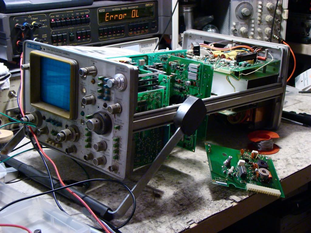
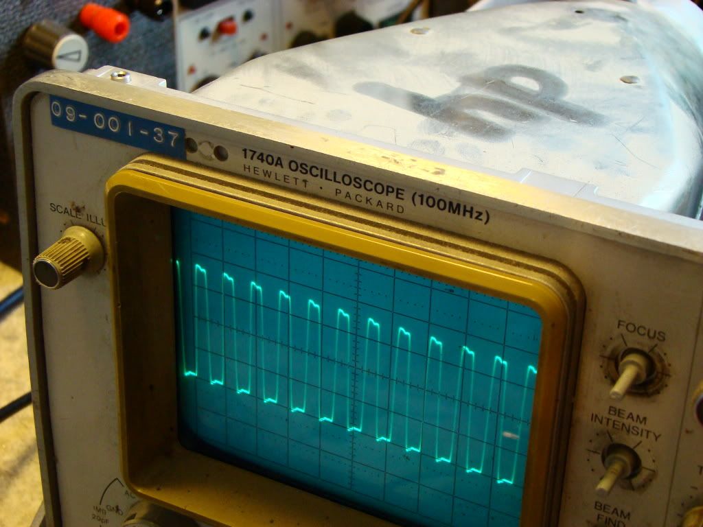
So first thing I would do wether the scope works or not is to measure the power supply voltages. If one of them is missing or low it may be causing problems in the storage system. Both my HP scopes had problems with the power supply.
So take off the covers and start probing. The mains cabling is shielded away under a small plastic cover (near the voltage selector) so the risk of shock is very small. The HV power supply for the CRT is also under an aluminium cover. The test points for the supply voltages are clearly labeled on the power supply board. Check +15, -15, +5, +48, +120, +156 and -100 volt supplies with a multimeter (the case of the scope is ground). If they are there and stable then move onward.
I strongly suggest reading the Theory of operation section of the manual. Try to follow the circuit diagram. If you look closely there are also important voltages written on some circuit diagrams.
I wouldn't say the tube is dead just yet. If it behaves this strangely even in normal mode it's probably another fault.
Besides HP never made a scope with the same CRT as the 1741 so replacement can only be done with the same tube.
Hi TekFan,
You were right.
The supply voltages are not ok. It seems at first glance that may be some problems with the power supply.
The burned diode is almost certainly failed, the resistance may be not.
Now I have to check in quickly in Theory of Operation section of the manual relevant parts of the schematic of the power supply.
Great work so far
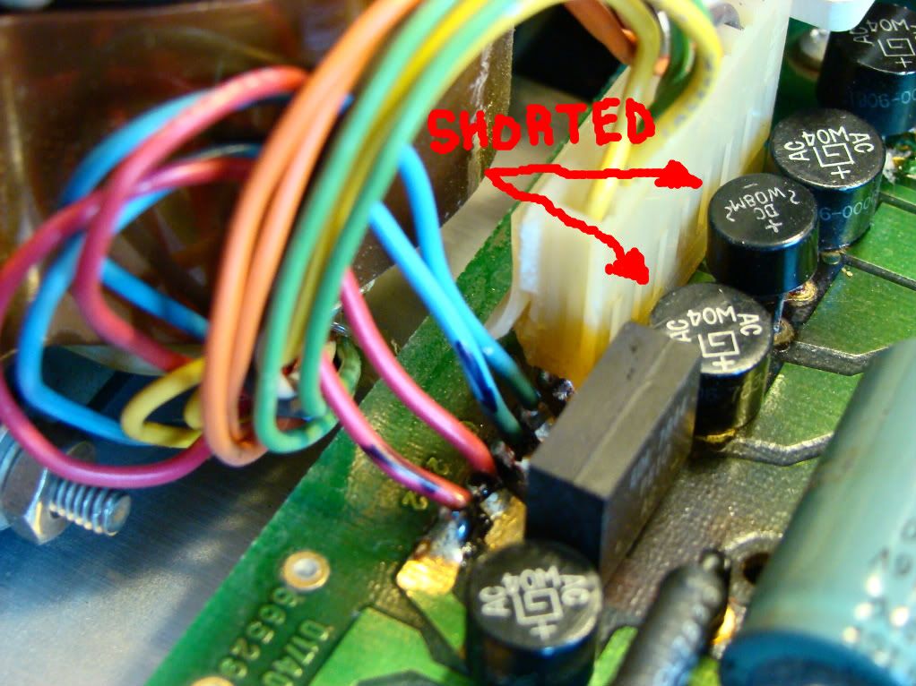
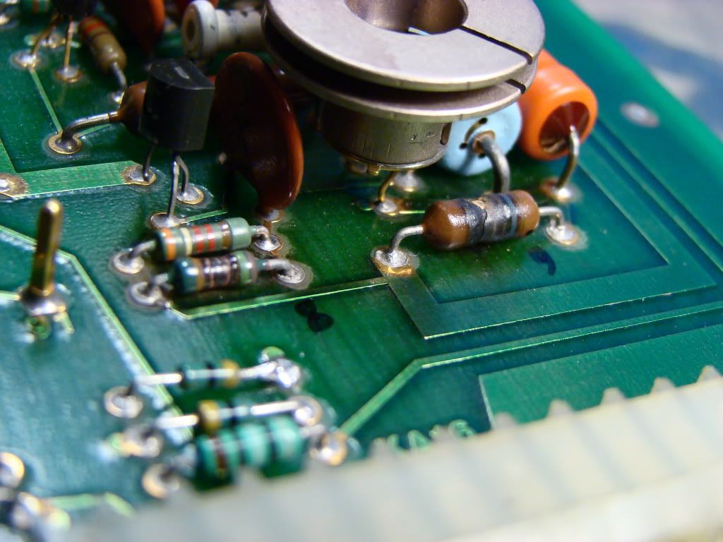
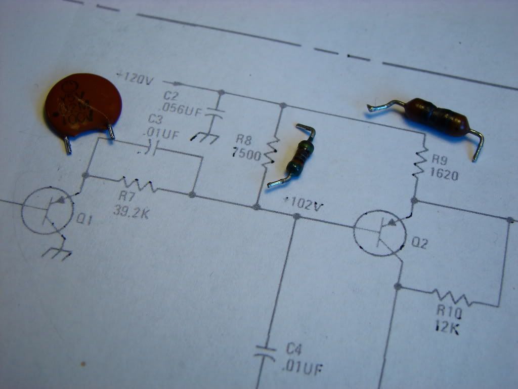
The resistor and diode are used as a primitive voltage regulator. That's actually a 100V zener diode in series with the 3.3k resistor. The -100V supply is used exclusively by the storage circuit so that may very well be the problem. The diode would probably have a too high voltage drop to be tested by a multimeter so the only hope is actual in circuit operation. The orange Sprague 10uF / 200V capacitor looks like it overheated from the nearby resistor. It will probably work if you leave still leave it in the circuit. They are very tough capacitors, but be sure to replace it in the long term.
Try to unplug the small board that interconnects all the boards in the scope. That way you can unload the power supply and see if the supply voltages rise to their nominal values. That way you can determine if there is a problem somewhere else in the scope. You can also slightly (or rather considerably) bend the boards out of the way so that you can connect the power supply to only one board at a time. That way you can isolate the problem at least down to board level.
Be sure to check the +48, +15, -15 and +5 volt supples. It's also used by the storage board. The unregulated +15V supply looks fine. It can actually be as high as 25V. The high voltage inverter for the CRT uses this supply. The other voltages also seem to be within spec.
I might add that both of my scopes had several faulty bridge rectifiers. When the scope is turned on you could hear the transformer humming loudly since the rectifiers had shorted. I also had problems with several shorted series pass transistors mounted on the back heatsink. Worth checking those with the diode test function. They are on connectors so no desoldering is needed.
Just keep measuring the thing. You'll eventually find what's wrong.

Tekfan: How do you clean the controls? I have a Tek 7934 which works very well but some knobs and buttons are stiff and/or "sticky".
Hi TekFan,
I replaced the diode, the resistor ok, 3,3k. Really, this resistor and diode very primitive voltage regulator solution. There was not 100v Zener at home, so I soldered together three diodes temporary (56 v + 33 v + 12 v). All three diodes are heating little bit, so it may need to add a series-pass transistor. Anyway, tomorrow I will buy a 100v zener.
I checked all the voltage again. It seems everything is ok (48, +15, +15, +5). I think so that each graetz works properly.
The result: in CONV mode the spot has disappeared.
I noticed a strange phenomenon in Conventional mode: The beam intensity does not function properly. When turning button the brightness increases linearly in the first period, then suddenly becomes brighter and then returns to its previous brightness level. From this point the brightness does not change any further turning of the button.
Surely there is a problem in storage circuit.
Turning brightness button:
I noticed a strange phenomenon in Conventional mode: The beam intensity does not function properly. When turning button the brightness increases linearly in the first period, then suddenly becomes brighter and then returns to its previous brightness level. From this point the brightness does not change any further turning of the button.
This is the screen protection kicking in. There's a maximum current limit trimpot in the HV power supply that sets the max current to the CRT. If this current is exceeded it will slightly reduce it by dimming the beam. If the spot on the screen is too bright it might permanently burn the metal storage meshes behind the screen.
When in storage mode there is a very small area where the beam is visible and the entire screen being flooded by the excess electrons if the beam intensity is too great. So you must use the minimum intensity to get a nice, visible display.
The brightness control is operating as it should. Somewhere in the middle position you should get a pre-fogged screen state (slight green spots appear).
The storage CRTs age quite a bit more noticeably than regular non storage. That's why regular calibration of the storage circuit is very important.
You can do a partial adjustment with only a screwdriver, multimeter and good eye. Look at page 43 where the storage adjustment section starts (especially paragraph 5-62). That will bring the brightness control back into the proper range. If you have another scope and a signal generator you can do a complete storage circuit calibration.
It seem that in the pictures you took the delayed timebase is turned on. Turn it off by rotating the outer timebase knob fully clockwise before making adjustments or storing images. It really works only in conventional mode since the intensified spot on the trace causes the screen to flood in storage mode.
Thank you very much for your continuous support.
Even I want to show this… the screwdriver was used enough.
Unfortunately, my another oscilloscope is broken too.
EMG 1568/2A (2x50Mhz). Search it with Google, it is interesting look at him. This is one of products of an former, now defunct Hungarian electronics factory, it it called EMG. Power supply also was defective, but I am still hunting for the fault because the electron beam is missing.
Do you know? I would not be so lucky…
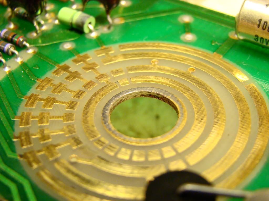
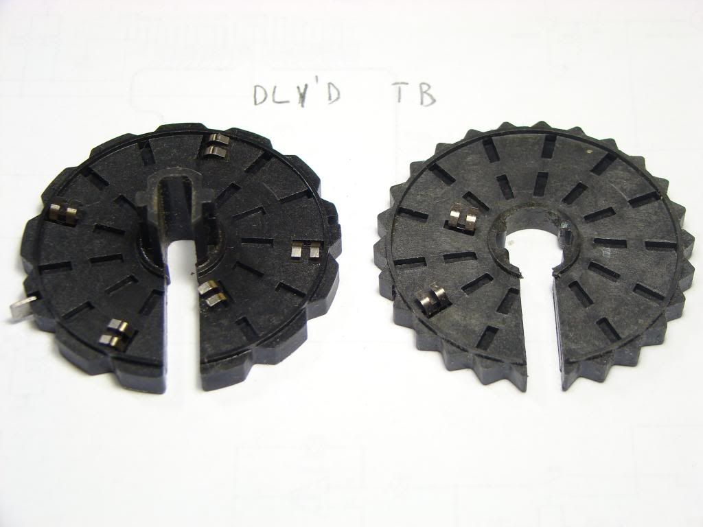
I was hoping someone may have a photo or diagram of the other half so I can make sure the contacts get put back to where they belong.
I'll dismantle the scope sometime during the weekend and post the pictures.
Luckily they didn't use multi-wafer switches. That would be a real pain to clean up.
I have a 1742 and a 1725 both of which need to be opened at some stage.
But from my recollection if you look carefully you should be able to see from which positions the contacts had been mounted. You can see small wear marks.
Hopefully you don't have any broken leaf springs. I have one broken one that I fixed with a banana plug and an angle grinder but It isn't a long term solution. I have some watch spring steel that I am going to use to fix it a bit more nicely. One day.
.
Someone must have lubricated the time division switch with something they shouldn't have
The lube/GLUE like goop is whats left of the original HP lube used on these series of CRO's.
Does not age at all well as you have found, how ever its easily removed and new lube applied.
I have cleaned half a dozen of these series oscilloscopes with this 'glue issue', and none of them
had been touched since new.
Sorry guys... Late reply. Busy weekend here...
I'll dismantle the scope sometime during the weekend and post the pictures
Tekfan - That would be amazing but probably above and beyond the call of duty... I hate to take up that much of your time.
But from my recollection if you look carefully you should be able to see from which positions the contacts had been mounted. You can see small wear marks.
HackedFridgeMagnet - Unfortunately no wear marks, not a trace to be seen. The PCB and wafers are in quite good shape aside from the glue problem.
Hopefully you don't have any broken leaf springs.
One is broken. One of the prongs got torn off. I think I'll be able to fashion something to take it's place.
The lube/GLUE like goop is whats left of the original HP lube used on these series of CRO's
Lowimpedance - Wow! Now that you mention it, that makes total sense. The inside of the scope is in excellent shape. I couldn't figure out why that gloop was the only invasion... When someone does something dumb to modify equipment, they usually do more damage than that!
I guess it was hard to HP to be able to predict how a particular lubricant was going to perform decades later... BTW, what did you use to re-lubricate the switches?
Thanks everyone. Your help is appreciated. -Tim
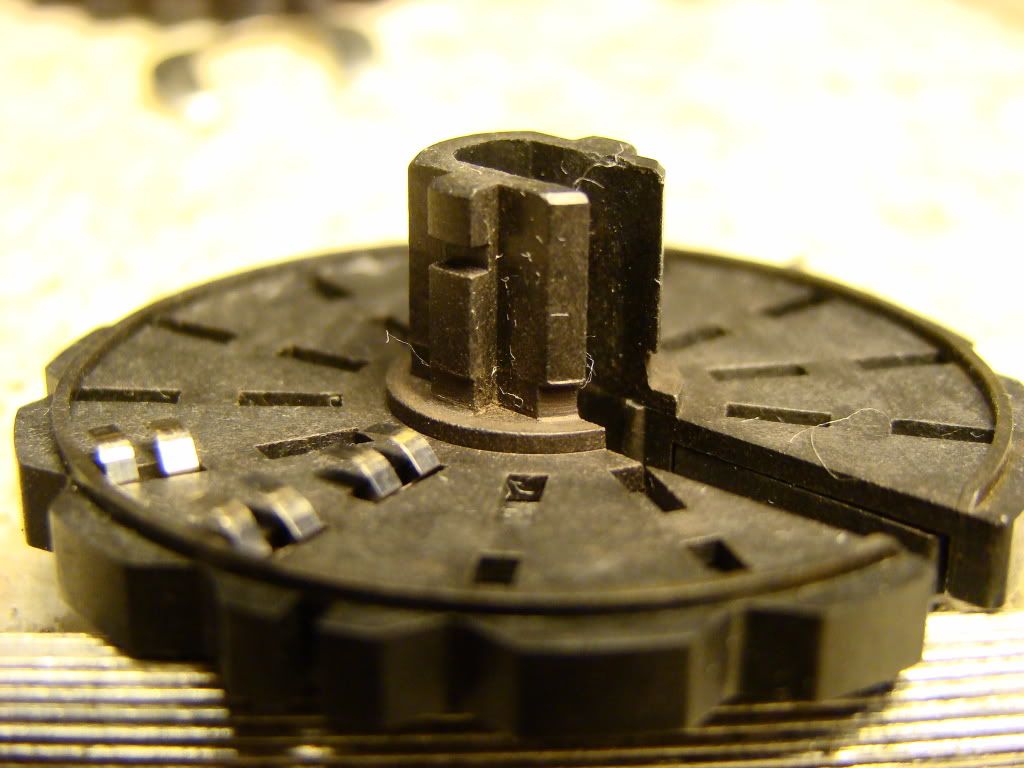
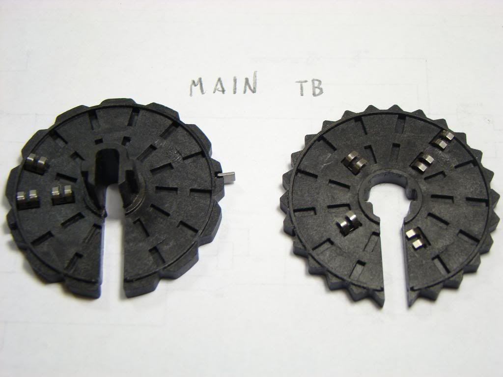
Here are pictures of the switch contacts
The contact positions should be exactly the same for the 1741 and 1740 scopes. I think the 1741 has some slightly different resistor values for the slow sweep speed holdoff time. It's a bit longer since you don't want double triggers when storage mode.
Main time base switches
Delayed time base switches
BTW, what did you use to re-lubricate the switches?
I used 'Electrolube brand' part no.SGB35SL (contact treatment grease) to carefully lube the contacts and also applied some to the axle hub.
Any 'suitable' grease you can get for electronic use should be okay. (The one I used I purchased from Farnell some time ago, have not looked
to see if its still stocked!). I used IPA to remove the fossilized grease (be VERY careful with the switch contacts,they are delicate!).
Tekfan... Thanks so much! I appreciate you doing that for me. I'd be happy to return the favour anytime. BTW, nice Leslie in the background of one of your photos on this thread.
Lowimpedance - Thanks, I'll find something that'll work.
Take care guys...
-Tim.
hello tekfan,
great job, congratulations.
The cold scopes are oftleny more complicated to restore then the glowing oldies.
I start now the restoration of my second triple nickel :-)
greetings from germany
Martin
I managed to fix the two broken contacts on the main time base switch. It is a bit tedious to get them just right. I got the spring steel from those stick on anti-theft tags that many stores put on their products. I think they are called "sensormatic" tags. Inside each one is two pieces of spring steel. One is a thicker gauge and it is pretty spot on the the gauge of the contacts. It is still thin enough to cut with a sharp razor blade. Far easier to cut out the shape of the contacts with that than a pair of snips... The spring steel in those sensormatic tags is real handy stuff. I always save those tags when I see them. Also, old windshield wipers have great spring steel in them for making small tools and the like... I grab that when I can too!
Best regards, Tim.
.Someone must have lubricated the time division switch with something they shouldn't have
The lube/GLUE like goop is whats left of the original HP lube used on these series of CRO's.
Does not age at all well as you have found, how ever its easily removed and new lube applied.
I have cleaned half a dozen of these series oscilloscopes with this 'glue issue', and none of them
had been touched since new.
Sorry to resurrect such an old thread, but I just stumbled across it and it is relevant to an issue I recently
encountered...
I have a HP 1725A scope and have cleaned the switch contacts of the petrified grease HP applied over
30 years ago. However, since I did not have any on hand I did not re-apply any contact lubricant.
Should I be worried? HP put it there for a reason... am I going to quickly wear the gold plating away?
I plan to apply some Electrolube in the near future but this thing will be OK for some normal usage in
the meantime, yes?
I've heard that gold contacts have self lubricating properties. If you look at most multimeters there's no grease in the switches.
Caig Deoxit G100L is tough to beat on gold contacts.