How test these ICs?
Replace! They are not expensive.
Install it in the sockets.
Replacement only for the same.
ok, I bought sockets and ICs some days ago. I can replace them quickly.
Krisz! I did not study the manual on the HP4274A.
With HP4275A they have a difference!

I waiting the morning! :-) If I replaced and the open and short calibration succes we are ok :-)
Hi,
I replaced the U8-9-10 IC-s but, ERR4 still flashing.
Please check the service manual 5.19 section. Maybe it is important.

Krisz
Hi. measure logical levels now.
Until you restore them, the car will not go.
The analog part here does not take part.


Your signal levels do not correspond to passport standards. The multiplexer controls these signals. It is necessary to bring this back to normal.
How can I restore when I measured the logical levels?
For this measure on A7 need the extension, because of the ICs at the bottom side of A7 board.
A7 do not touch yet.
You need to measure the levels again at the input of U5.
Make again the table and compare it with the previous one.
Further in the chain on A3, you did not check the last node.
This is LATCH! It can inhibit the passage of the signal to U8 / U9 / U10.
To do this, it was installed. With him you need to understand.


3g57
Hi,
I have been following this thread. Are you sure that your HP4274A is broken?
Let me show you what happens with a perfectly healthy 4274A.
If I press the ZERO open button with no fixture connected to the HP4274A Err 1 is displayed:

If I connect an HP16047A fixture to the HP4274A and press ZERO open, the HP4274A displays CAL until the ZERO open is complete:
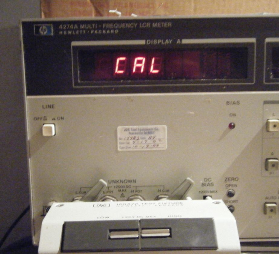
If I connect all the shield of the BNC connectors together and connect Lcur to Lpot and Hcur to Hpot and I press the ZERO cal the test is performed the same way as with the 16047A fixture:

Here is a close up of the wires:
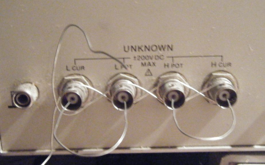
The BK Precision Test fixture may not be wired the same way as the HP fixture. I would check it.
Regards,
Jay_Diddy_B
Hi,
I tested the zero calibration with simple wires, but first time CAL, ERR1, and ERR4 flashing.
In zero offset adjustment need to set the multiplier in x5 position? the user manual says yes.
I found an article that BK fixture working with 4274A.
http://k6jca.blogspot.com/2017/11/replace-hp-16047a-test-fixture-with-bk.htmlI think need to work the fixture with 4274A.
A little history: When arrived the 4274A first time worked, but I don't had a fixture. I made a handmade fixture using alligator clips, and it is worked. I could measure R C L parts. Then I left from my workshop, but the 4274A stayed power on. 2 hours later I came back, and ERR4 flashing on display. I don't know what happened, nobody touched the 4274A.
Can you send me a similar photo from 4274A? Need compare with yours. You see this if Push the SELF Test and D button.
Thanks!
Regards,
Krisz
Krisz and the group,
Here is the self test section from the manual.
This is a summary:

Regards,
Jay_Diddy_B
Hi,
Here are the results from my 4274A with the 16047A installed:

Regards,
Jay_Diddy_B
Hi,
The rest of the self-test results:
Regards,
Jay_Diddy_B
Hi! Krisz.


The only digital bus that goes
on A3 this is STROBE CLOK DECODER.
She manages DSA-2. Even when checking (see FIGURE 8-31), I send the instruction to the address U216 (MC U20 74LS74N).
Here, a signal is generated for the digital part A3.
This creates the necessary signals for U8, U9, U10. LATCH.
A task:
It is necessary to achieve the normal operation of these microcircuits(MULTIPLEXER).


3g57
Hi all,
Quick I made a video about the self-test:
At A3 TP3 I found 1Vrms. But this value depends on FREQ and Multiplier settings.
Flowchart wants there 3,3Vrms. How could be 3,3 Vrms if depend on multiplier?
Multiplier x1, FREQ 1 kHz:

I checked the A7 board test points:
A7TP10 - Hi-Lo switching
A7TP11 - Hi (+4V)
A7TP12 - Hi-Lo switching
A7TP13 - Hi
A7TP7 - Hi (+5V)
A7TP18 - Hi
A7TP5 - Lo
Krisz
PS.: May I replace the A7 U20?
Thanks!
Krisz
Krisz! Hi.
You can replace U20. Install it on the socket.
Look at the situation.
You make measurements and do not specify under what regime it was done! It is very important. You give the results of measurements. How can I guess? The digital part does not work correctly.
Look at your last measurements! Tp11-A7. pin # 34 * RESET *.
You have a high level on it. It is activated.
The * ENABLE * Tp10-A7 pin # 25 is followed by continuous
switching (A7TP10 - Hi-Lo switching).
Why is this happening and under what conditions?
It is necessary to measure the reference frequencies of quartz
resonators. Pretty sure. The instruction writes about an error up to 20ppm.
There are three quartz resonators.
* RESET * can occur due to the breakdown of the reference (inaccuracy) frequency.
p.s. I asked the mail about the battery. There was no answer.
You can not do without an expansion board.
3g57
Hi,
Sorry, I just now see your messages. I did not get an e-mail about the new post and the PM message. I ordered the U20 IC, it is will arrive circa Friday.
I always made the measurements with the default settings, except if flowchart or you don't want other settings.
On my 4274A not installed the memory backup option. If exist other battery where can I find it?
I think I order 2 extension card from the original manufacturer:
http://www.douglas.com/index.php/6-de-6.html with sockets. I ask them, what is the real shipping cost because the calculator said 100-200 USD. It is too expensive for these little cards.
Krisz
Hi,
It is my A9 board w/o battery. I measure again on the A7 board?
Krisz

As I discovered when repairing my 4275A, you are better off leaving the battery out while troubleshooting. Also remove the GPIB board (and DC bias bpard if it has one) until you find your problem(s).
Also remove the socketed EPROM labeled "19", that is for the GPIB board.
Hi 3g57,
The U20 IC has arrived. I replace them. Maybe it was broken.
Update: Replaced but nothing changed. Still ERR4 flashing
Krisz
Hi,
The brand new original Sony C1636 transistors have arrived. I tested them, and replace on A3 board.
Krisz
Hi all,
Looks like my HP 4274A working fine finally. Thanks for the useful informations and tips for all. It was a long adventure, and I learned a lot of things about the world of the TTL. Little later i make a post and I will write the repair process, I have tons of pictures and some useful info, maybe helps for somebody. And well now I will open a bottle of beer.


