I looked through the list at the top of the thread, but didn't see anything (maybe I'm blind

). Has anyone successfully made feet for older style HP gear such as the 8640B sig gen?
I posted a video link showing this 121GW tilt stand extension in the 121GW Discussion thread and have now included a direct link to the item as well. This is not my product so if you use it be sure to give credit and thanks to the person who did the work.
https://www.thingiverse.com/thing:3666409
Thanks beanflying for this great resource - some of my HP and one TI calculator files
Battery door and catch for HP 41CV printer HP 82143A
HP 34702A Foot
TI Calculator Battery Door
Catch for the HP Classic calculator battery door - they break a lot
Edit : Zip Files separated
Thanks again beanflying

Thanks beanflying for this great resource - some of my HP and one TI calculator files
Battery door and catch for HP 41CV printer HP 82143A
HP 34702A Foot
TI Calculator Battery Door
Catch for the HP Classic calculator battery door - they break a lot
Can you maybe split the Zip so the contents are easier to link to or know what is inside? Doesn't need top be separate posts just maybe edit the one above then I will add them individually into the index posts.
Hey guys. I ran into some broken Xantrex XPH power supplies with missing output buttons. I've attached the CAD in stl for 3d printing the button.
These buttons should work on several sorensen / xantrex / tti model power supplies.
Here's what it looks like on the front panel now (the black button in the bottom right corner)
The measurements were taken with a caliper on an OEM button from another psu.

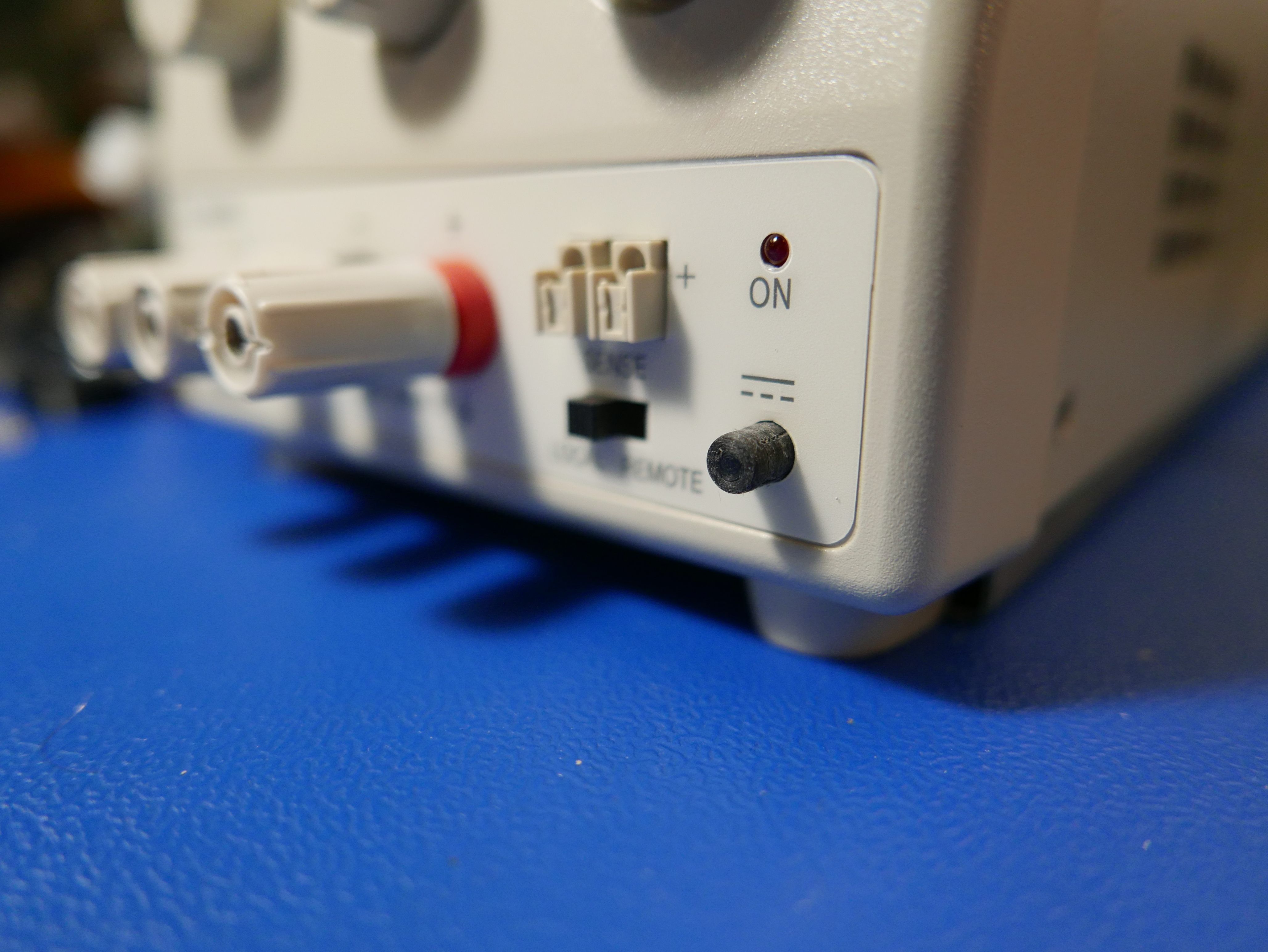

The plastic button is a press-in install. You don't need to remove the front panel of the PSU to install it. The PSU uses a latched output button like old 90s computers. The button stalk is even similar in size.
The part is tiny (less than 0.5in x 0.25in x 0.25in size) and should only take minutes to 3d print.
There are (2) files attached. One features a perfectly cylindrical button and the other has a 1 degree draft.
The OEM output button has a 2 degree draft, but it is purely cosmetic and may cause problems in 3d printing when printing from the side of the smaller diameter.
Ideally, you want to print from the side of the button without the hole so you don't need to clear any support material.
Let me know what you think!

Hey guys. I ran into some broken Xantrex XPH power supplies with missing output buttons. I've attached the CAD in stl for 3d printing the button.
These buttons should work on several sorensen / xantrex / tti model power supplies.
Here's what it looks like on the front panel now (the black button in the bottom right corner)
The measurements were taken with a caliper on an OEM button from another psu.
The plastic button is a press-in install. You don't need to remove the front panel of the PSU to install it. The PSU uses a latched output button like old 90s computers. The button stalk is even similar in size.
The part is tiny (less than 0.5in x 0.25in x 0.25in size) and should only take minutes to 3d print.
There are (2) files attached. One features a perfectly cylindrical button and the other has a 1 degree draft.
The OEM output button has a 2 degree draft, but it is purely cosmetic and may cause problems in 3d printing when printing from the side of the smaller diameter.
Ideally, you want to print from the side of the button without the hole so you don't need to clear any support material.
Let me know what you think!
Depending on the space on the top of the button or hole as the case may be model in a 45 degree chamfer is an easy way to avoid needing support material to keep a desired bed orientation. I use this sort of solution fairly often and if you run 0.1mm layers you can push this to nearly 60 degree overhangs without major sagging.
My turn to play with the 121GW with a Magnetic and webbing loop hanger.
The webbing one has been printed and works great and I am waiting on magnets for the other but the modded end should print fine.
6 layers all round, 40% infill, supported on the bed only works fine at 0.2mm layers. While PLA works consider using PETG as it is tougher for impacts and the release catch will flex easier. Print it on edge as the STL in the Zip files below.
Magnet source -
eBay auction: #183364882157 20x10mm with 5mm countersunk bore. Also needed is a 5x18mm screw and nyloc nut (or nut and lockwasher)
Fluke 5440B/510x/850x feet. - cross posted from a WTB thread so it doesn't get lost.
Where else would I be on a wet and cold Saturday afternoon. I was going for a bike ride then 7 degrees and falling my brain made other decisions and there was beer.

Obviously not an identical clone but one that leans toward easy printing and matching heights of the real one. Print them on their side for strength on the pips that go into the case. 0.2mm layers with bed only support worked fine.
I have made it to take these 12x12x5.8mm feet readily available on evilbay
eBay auction: #143252416915 which like the real one lifts the feet clear of the bench but then stops it from clipping over the side of a unit under it.
STL is in the Zip file.
This thread is pretty hard to find with the search tool... but I've been gradually making and testing models for other equipment, so here's an update with some additional contributions to the library:
R&S Feet for SMIQ/SMT/SME/FSEA/FSEB/FSIQ/ZVR/ZVRE and maybe more - complete with kickstand
https://www.thingiverse.com/thing:3882663R&S power button for SMIQ/SMT/SME - probably others, but they use a different kind of switch and I haven't tried to pull them off to check
https://www.thingiverse.com/thing:3882440R&S front knobs for SMIQ/SMT/SME, big knob compatible with at least FSEA/FSEB/FSIQ/ZVR/ZVE
https://www.thingiverse.com/thing:3827226LeCroy Wavepro 7k/8k/SDA/DDA/Wavemaster front bezel and power button - broken up into parts to be printable on a smaller machine
https://www.thingiverse.com/thing:3834875Phase Matrix Inc. EIP 25/28+ microwave counter feet - likely compatible with all EIP counters, don't have them to check
https://www.thingiverse.com/thing:3817945Triwing security SMA wrench - couldn't find one for sale, printed in polycarbonate to good effect, fits around even a longer SMA connector to remove the security nut
https://www.thingiverse.com/thing:3832862Also I hate that thingiverse now changes the aspect ratio of uploaded pictures for no reason.
It is not exactly a replacement, because you can only obtain it that way, but there is a reasonably usable stand for the PEAK series of instruments (LCR45, DCA55, ESR70 etc) which found on their website, but it does not seem to be available anymore. Therefore, here it is (2 versions):
So that's HP and Tek feet, an LCR45 stand, various enclosures so far which are looking useful. This thread is slowly costing me a 3d printer.
So that's HP and Tek feet, an LCR45 stand, various enclosures so far which are looking useful. This thread is slowly costing me a 3d printer.

Just stop resisting you know you need it. Think of all the crafty prints for your girls available on Thingiverse too ....

Bit busy but I will add the last couple of posts to the indexs when I have a minute.
Hahaha I asked them about it and it’ll be pen pots galore
What 3D cad software do people recommend? I want to avoid Fusion 360 if possible. Mostly interested in relatively simple enclosures, test gear parts and test fixtures.
Edit: ok I bought one. And am learning FreeCAD. I have some experience with SolidWorks and ME10 already going back a looong while so need to dig deep in the brain.
I use Rhinoceros 3D, been using it for 15-odd years and love it.
Wow! I wish I'd found this thread 2 weeks ago before I ordered the U1179A IR Clip for my U1242B meter. Is the knob design by beanflying the same as the slightly tapered 0370-3238 HP knobs used on the 6xxxA DC PSUs eg 6643A?
I've been 3D printing for fun for a few years. I have a Qidi Dual head 3D printer (FlashForge Creator Pro clone). I design my own parts using FreeCAD 0.16 which I taught myself by watching youtube videos (I tried 0.17 but it weirded me out because everything seemed to have changed), and I use Simplfy 3D for my slicer. I also modified the printer bed to use a glass plate but I need to improve the holding down of that plate using something better than bulldog clips because it's not good for the heads if they crash into the clips.
Well I checked into my order (from Keysight) for a U1179A IR Clip and it hasn't shipped and that 16 days after I placed the order and paid for it! How USELESS! In a fit of annoyance, I cancelled my order and got an email saying they were going to ship it to me on Monday and will try to cancel the order - PAH!
Then I designed my own (which cost me way more in time than $17) and vn 1 is printing as I write this.
@beanflying, I've attached pictures of the PSU & knobs I'm talking about (I have another supply that's missing the knobs and is using gaudy Chinese ones). They are tapered, push on, and have a flat internally.
[EDIT1 Yes I can import STLs into FreeCAD but I'm not a FreeCAD expert by any stretch of anyone's imagination
[EDIT2] It looks like the one you linked to may be a winner
although it doesn't have the flat internally it even has the internal flat
So here's my attempt at a replacement for (not copy of) a U1179A. I looked at the fitment on the back of my U1252B that, for some inexplicable reason, is missing from the U1242B and melded that with my detailed digital caliper measurements of the back of my U1242B. The pictures show the result and I've also attached the stl file.
I had issues printing it in PVA which seemed too brittle and broke, the grey stuff is eSun PLA+ and, after playing with the temperature settings, I got acceptable results in the grey color shown This works well with my U1117A BT adapter and my U1173B USB-IR cable.
I was trying to print that knob today but the Simplify 3D slicer doesn't like it. It looks OK on the import but when I try to process for print, it looks like this....
Any ideas?
The walls are too thin for your extrusion width? I'd look to see if there's a "detect thin walls" setting or something (that's what it is in slic3r/prusaslicer), and make sure that your extrusion width (often slightly larger than your nozzle width) is small enough to accommodate the wall thickness.
That said, I'd change the model. I would fill in all of the air gap between the outer shell and the inner shell that connects to the D shaft. In injection molding, you leave that blank because it uses less material/lightens it up/doesn't improve durability.... but with 3d printing we have infill. Fill in the gap in the model, let the slicer fill it with whatever loose infill you choose, and then you have no wall thickness issues on either side, even if you want a super durable like 4 or 5 perimeter wall.
@DajMasta
Thanks, I found the thin wall settings in Simplify 3D but that didn't fix the issue. Your suggestion is a good one but the link to thingiverse gives an stl and a 3dm (Rhino) file and FreeCAD can't work with Rhino. I am not confident enough in my CAD skills to tweak the stl file.
Is any good Samaritan eevblogger here willing to tweak the 3dm file for us?
Not 100% sure what model you're talking about? I looked at some of the HP knobs in the thread and they look pretty dramatically different from that render.... and most of them have wall thickness that would be fine to print already. I also haven't been able to find one in a 3dm file format?
I wonder if the slicer is just having trouble with something about the file. I know some model files can have oddities that certain programs don't like. Trying another slicer (or even just loading it in a renderer) to verify could be good, but there may also be an option to fix model problems automatically which could help. Since I don't quite know for sure without the original model it's hard to say, but maybe some of the internal structure has been inverted? Does it look OK before you slice it?
I think he was playing with JohnPi's design which is like the modern knobs with a hollowed cavity. Shouldn't be hard to rehack one of mine to a push on encoder version but I am playing Laser Boy at present.
 SVG File in the zip.

 Just checked and I uploaded the lot here to google drive due to size https://drive.google.com/file/d/16TDa7CEWRLShBq6--NWDScFT7Y22YXop/view