Thank you for breaking that down for me! I really appreciate it! Man, I really thought that was it. I tried going to the one you speced out earlier but I couldn't find the part number. When I clicked the link you had up, it gave me a 404. I went to their website and clicked on the data sheet, it gave me a 404 too (from Copal's website).
Try the link again. I updated it to point to a copy of the file on my GoogleDrive.
It says I need permission to view. I requested permission. You might want to adjust the permissions so everyone can view without having to request permission. Than again, there might be a reason you have it setup that way. Thank you though, I think we're getting closer to me seeing the PDF!
Done, made the permission change.
Thanks everyone for sharing this was a great thread.
joneggert, that switch appears as though it will work, electrically and mechanically. The difference between it and the one I bought is the toggle handle; your switch has a standard metal bat handle.
I checked the
same part number on Digikey and it is currently in stock as well.
Why does the scope have such a long winded grey cable inside?
That winded cable on the right seems miles long

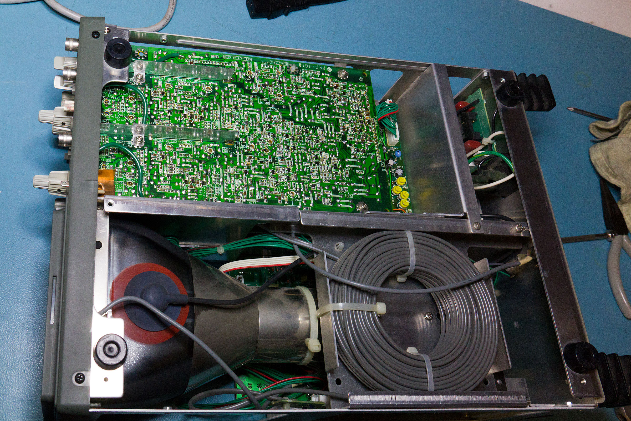
The wound cable is a delay line to give the delay triggering feature of the scope.
The wound cable is a delay line to give the delay triggering feature of the scope.
Not quite, it is a delay line but not to give the delayed trigger.
It is there so that you can see the edge on which the scope triggered for fast signals, most good quality higher bandwidth (certainly anything > 100MHz) analogue 'scopes have them.
Ah, ok. Thanks for correcting me.
Hi I used to sell these scopes when I worked at stc instrument services sold well against them and I liked them a lot. Back then the trigger lock was a big plus for some users.
I have one now an ex demo unit that saw very little use.
But the uncal knob on the channel a attenuator is broken off. I have removed the board and undone the circlip at the pot end so its an easy task to change it.but making one is a bit of a challenge.just wondered if you might sell me one off your parts scope? I live down in France. By the way I think we used to charge quite a lot extra for the a option. Never new it was that easy to change! Done mine while apart thanks to your info many thanks.
Might even be able to find an old cat here somewhere.
Hi,
I need to change 3 push/pull pot on my HITACHI VC-6023, instead of creating a new thread I ask here. The reference in the service manual are EVHYK3325B14 which is 10K push pull. Does anyone know the manufacter or a suitable replacement ?
Thank you for your work on Hitachi 1565 - it's great! Tell me in the photo there is a highlight of some buttons of the oscilloscope itself, this is tuning or there is such a modification. Look at the photo. Thank you .
Thank you for your work on Hitachi 1565 - it's great! Tell me in the photo there is a highlight of some buttons of the oscilloscope itself, this is tuning or there is such a modification. Look at the photo. Thank you .
The 'scope didn't have a cover on when I took that photo - it's just light from above shining through the PCB in the 'scope.
About the frequency counter on the Hitachi scopes.
I have a 1585 and I'm frustrated by the frequency counter accuracy too. This model has a PEF-875 board and there's the uC and the frequency counter. I applied 1MHz from a Ublox GPS module and it reads 998.1KHz. If I touch one of the pins of X4101, the blue resonator in the picture, with an oscilloscope probe connected to a reasonably accurate frequency counter, the reading goes up to 999.6KHz and the frequency counter reads 12.006MHz. As you can see in the picture, there's a place for crystal oscillator but they decided to use a ceramic resonator. Really Hitachi? The PEF-875 board seems to have two 32 pins headers soldered to the one beneath so would be pretty hard to remove it and I may damage some pads. Again, really Hitachi?
I, being a bit of a precision nut, intend to desolder the resonator from the top and install a crystal that has much tighter tolerance and stability than a ceramic resonator. By my calculation, the crystal must have a load capacitance of 21.5pF so I don't need to change the two 33pF load capacitors shown in the schematic. A 20pF CL crystal should do it.
I'll let you know how it goes.
The resonator is out, ready to receive the crystal.
All done, the crystal is in and check this out...bang on.
Why did I do it? Do I need this accuracy? Of course not, it is called OCD ... Oscilloscope Compulsive Disorder

Interesting upgrade. I have a V-695. I have to see if I can do this modification, or even if it is necessary to do it. You modified X4101 on the PEF-875 board from a 12MHz resonator to a 12.000 MHz CL crystal if I understood correctly.
I'm not sure of the exact differences in the frequency display hardware between your V-1585 and my V-695. If my V-695 scope is equipped with a PEF-782 board, would I consider doing this modification to X3101, which is also a 12.000 MHz crystal?
Nicely done, Miti. Why did you do it? Because you could. And it looks cool. Sounds good to me.
Interesting upgrade. I have a V-695. I have to see if I can do this modification, or even if it is necessary to do it. You modified X4101 on the PEF-875 board from a 12MHz resonator to a 12.000 MHz CL crystal if I understood correctly.
I'm not sure of the exact differences in the frequency display hardware between your V-1585 and my V-695. If my V-695 scope is equipped with a PEF-782 board, would I consider doing this modification to X3101, which is also a 12.000 MHz crystal?
Most likely that's the ceramic resonators that you need to change. The easy way to validate that, apply known accurate 1MHz and see what the frequency reading you get. If it is bang on, you're good, you don't need to replace anything . Then touch one of the resonator's pin win an oscilloscope probe and observe if the counter reading changes. If it does, that's your culprit.
Cheers! thanks for the explanation.
Well just brought a vc6025 the digital storage version of the 665 and low and behold the same mode for the frequency counter works perfectly on that.
In search of a good analog oscilloscope I bought Hitachi V-660 on ebay. The device turns on, trigger is work , but the image is distorted. I already study the manual, I ask the advice of experienced specialists - this can be a defect in the CRT tube?

. Thank you. Photos from this topic are very similar to my device.
p / s / I think the problem in sweep generator PEF-865.
A first step might be to replace capacitors on the boards. They might have aged badly.