-
Insulating the shaft from the frame with non-conducting balls is probably not a good idea. It's much easier to insulate the frame from ground.
You can measure the voltages on the circuit FETs without the capacitor connected: there is no point in trying to make it oscillate before the amplifier is working.
Are you sure you have connected the FET leads correctly? While the D and S can usually be interchanged, exchanging the G with one will result in a useless transistor. -
Insulating the shaft from the frame with non-conducting balls is probably not a good idea. It's much easier to insulate the frame from ground.
Now the capacitor is dismantled, so I might as well do some cleaning.
I do not understand how else to insulate the frame from ground. The shaft is electrically connected to the frame with physical connections. One of those connections are the metal balls.
I never connected the frame or rotor shaft the the ground on the breadbaord. The only thing I connected to ground was the stator of one of the gangs.
I am clearly not understanding how I have to insulate the frame from ground.You can measure the voltages on the circuit FETs without the capacitor connected: there is no point in trying to make it oscillate before the amplifier is working.
Are you sure you have connected the FET leads correctly? While the D and S can usually be interchanged, exchanging the G with one will result in a useless transistor.
I triple checked the pinouts, on the datasheets as well as on the transistor tester.
Perhaps I should just flip the drain and source and see what happens.Beryllium is alloyed to softer metals like copper and gold in order to stiffen them without work hardening them.
In this case that would be to make the copper clips retain their springiness over time.
I should think the chance of releasing beryllium particles to be vanishingly small, unless you decide to use an angle grinder on them or something.
I guess the beryllium copper clips are what I called leaf springs. I am glad I know about the beryllium. Those solder joints were not easy to heat up and it is not out of the realm of possibilities for someone to reach for a mini grinding wheel on a Dremel tool to cut through the solder joints.
-
Before proceeding further, you need to find out what the DC voltages on the two-FET amplifier are. The drain voltages you measured indicate total failure of the amplifier circuit. It wouldn't hurt to verify that the frame is insulated from circuit common with a simple ohmmeter check.
-
Before proceeding further, you need to find out what the DC voltages on the two-FET amplifier are.
If I read the datasheet correctly, I believe the MPF102 FETs are rated for 25V.
https://www.onsemi.com/pub/Collateral/MPF102-D.PDF
I already cleaned up the capacitor and I am attaching some images. I used hydroclhloric acid and when I was done I used a baking soda solution to neutralize the acid. After I rinsed with water and used an air gun to dry it off. I managed to remove a lot of the surface rust. I am attaching some images.
I am not sure if the mica trim caps survived.
I reassembled and tested that there are no shorts. I did end up using the acrylic balls, since the steel balls are in fact rusty. As a result there is no more continuity between the rotor and the frame. To connect the capacitor to the breadboard I can just use a jumper straight from the rotor. Later I will reattach the spring clips.The drain voltages you measured indicate total failure of the amplifier circuit. It wouldn't hurt to verify that the frame is insulated from circuit common with a simple ohmmeter check.
First I tested the circuit by swapping the drain and source. Results were the same. Then I completely dismantled the circuit and reassembled using different parts of the breadboard. Again, results were the same.
I took some voltage measurements.
With 18V applied to the circuit I get the following.
Q1
Drain - 2.28V
Source - 2.09V
Q2
Drain - 2.77V
Source - 2.44V
Nothing changes if I turn any of the three pots.
-
With only a few tenths of a volt between your measurments of "Drain" and "Source" voltages, I still suspect that you have mis-wired the device. Note that the Gate is not the center connection, but one end. In that circuit, the gate must be negative with respect to both Source and Drain, to reverse-bias the gate-channel diode. You did not state the actual voltages at the two gates: in this circuit working properly, the gates are connected to ground through relatively large resistors. With a miswired gate, the nodes might be at substantial positive voltage, which might explain the bad voltages on your D & S measurements.
By the way, if you insulate the shaft from the rotor with plastic balls, won't the leaf springs make the connection again? -
With only a few tenths of a volt between your measurments of "Drain" and "Source" voltages, I still suspect that you have mis-wired the device. Note that the Gate is not the center connection, but one end.
It is a real mystery because I did in fact check multiple times that this is wired properly. The gate is in fact pin 3 and I did wire the gate of Q1 to the rotor of the big cap and I wired the gate of Q2 to the wiper of the R12 pot. I also checked (several times) on the transistor tester that the FET pinouts are correct and that they match the datasheet. I feel like I am loosing my mind.
Perhaps one of my breadboarding jumpers is bad. I am going to rewire everything.In that circuit, the gate must be negative with respect to both Source and Drain, to reverse-bias the gate-channel diode. You did not state the actual voltages at the two gates:
The voltages from the gate to ground read 0V on both transistors.in this circuit working properly, the gates are connected to ground through relatively large resistors.
The Gate of Q2 is on a wiper, so wouldn't that mean that the gate could potentially be shorted to ground if the wiper of R12 is turned all the way towards ground?By the way, if you insulate the shaft from the rotor with plastic balls, won't the leaf springs make the connection again?
When I initially dismantled the cap I was planning to reinstall the spring clips on some kind of non conductive material. At this time I did not do that. I simply used a jumper from the rotor to the point on the breadbard.
I am still confused about how the case of the capacitor needs to be separated from ground. I never wired it to ground. I I only wired the stator of gang B to ground, as per the schematic. -
OK, I built another circuit on another breadboard, using all new components and all new jumpers. Tested each component before using it.
This time I get different voltage readings but still a flat line on the scope.
With 18V supply:
Q1:
S - 1.69V
D - 5.17V
G - 0V
Q2:
S - 0.72V
D - 13.94V
G - 0V
I don't believe I wired up anything differently, but as you can see I am getting different voltage readings.
Does this make any sense?
Thanks...
-
Those voltages look reasonable. If you disconnect the feedback network (tuning capacitor still removed, only R5 to R8 switched from the gate of Q1 to ground) and feed a small audio signal (say, 100 mV rms at 1 kHz) to the gate resistor, what do you see at the output? Sometimes you need to check subcircuits before connecting them all together.
Since I currently don't have an audio generator I had to rig something up. I used a sine wave generator board that I made a while ago and used a 5k pot to adjust the output to 100mV RMS. The frequency happens to be 1.165kHz.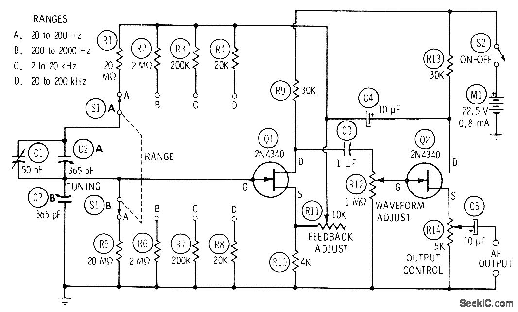
What I see on the output is an inverted, slightly amplified, signal. The image shows what I see when the output control pot R14 is dialed to maximum output and the waveform adjust pot R12 is dialed up, so that the signal from drain of Q1 goes straight into gate of Q2. When I dial down R12, so that gate of Q2 gets shorted to ground the output is a flat line, as expected.
When I measure the RMS voltage at the output it reads 145mV.
I'm not sure if that's what's expected.
Thanks...
-
Looks reasonable. For the next diagnostic, replace the variable capacitor with two equal fixed capacitors and see if you can make it oscillate.
-
Looks reasonable. For the next diagnostic, replace the variable capacitor with two equal fixed capacitors and see if you can make it oscillate.
The smallest value fixed value caps I have on hand are 1nF. I tried with those, and some higher value ones, and I do not get oscillation.
However, I did at least figure out what one of the problems was.
For the second circuit that I built I used MPF102 FETs from a different batch. When I plug those into the first breadboard I do get that circuit to work the same way as the second breadboard. And when I plug the FETs from the first breadboard into the second breadboard, then the second breadboard no longer works.
I have a few of each type of MPF102 in stock and none from the first batch work but every one from the second batch that I tried works.
Below is a photo of the two, side by side.
The one on the left is from the second batch (the one that works) and the one on the right is from the first batch.
If I recall, I bought both batches from Jameco, but at two different times.
-
1 nF = 1000 pF is a bit high, but I would think it would work. If you can find some 100 to 220 pF caps, they would be worth trying.
When the "oscillator" flat-lines, are the DC voltages the same as when the feedback is connected?
It's conceivable that the two batches have different pinouts, but that would be strange. Probably just defective parts. -
1 nF = 1000 pF is a bit high, but I would think it would work. If you can find some 100 to 220 pF caps, they would be worth trying.
I managed to find some 220p caps I didn't know I had. When I connect them I still do not get oscillation.
When the "oscillator" flat-lines, are the DC voltages the same as when the feedback is connected?
It's conceivable that the two batches have different pinouts, but that would be strange. Probably just defective parts.
I did the DC measurement tests.
Test 1. When the 100mV signal is connected to the gate of Q1 and there are no 220p caps in circuit.
Q1:
D - 5.14V
S - 1.69V
G - 0V
Q2:
D - 13.92V
S - 0.73V
G - 0V
Test 1. When I connect the 220p caps.
Q1:
D - 5.125V
S - 1.69V
G - 0V
Q2:
D - 14.02V
S - 0.72V
G - 0V
Hope these measurements make sense.
Thanks... -
OK--it looks like connecting the feedback has no effect whatsoever--I would carefully re-check the connections around the feedback network to the gate of Q1--something is missing.
-
OK--it looks like connecting the feedback has no effect whatsoever--I would carefully re-check the connections around the feedback network to the gate of Q1--something is missing.
Is it possible that the schematic is wrong? I know 100% that my circuit is built exactly as the schematic shows.
However, I question that resistor R10. There is no standard 4K value is there? I put a 3K9 resistor there. Perhaps that should actually be a light bulb and somehow that detail got lost in translation when someone copied the schematic.
Could that be the problem?
Thanks... -
The standard Wien bridge has a reactive leg (R + C) feeding (R || C) for positive feedback and a resistive leg (2R feeding R) for negative feedback. The 4k R10 is the "R" in the resistive leg, and should be half of R11 = 2R to get an open-loop gain of +3, while the reactive leg has a gain of +1/3. Therefore, the variable resistor R11 should be set to 8k to balance the bridge. Usually, R10 would be a temperature-sensitive thermistor. However, with a 3.9k fixed resistor, changing R11 should achieve oscillation of some kind, either increasing to a distorted waveform or decreasing to flat line. If R11 is too small (due to a bad part or connection), then the oscillator will not start.
Circuit signal tracing: with the capacitor network disconnected from the gate but connected to C4, do your gain test again from the gate of Q1 to C4, then to the junction of the two "C2s". You should get a gain close to unity from the gate through C4, through the reactive leg, to where the gate was disconnected. The magnitude matters: oscillation requires an exact loop gain of unity at zero phase. The feedback through the reactive leg should be +1/3 at the frequency determined by the R and C: f = 1/(2piRC).
To simplify the explanation of the reactive leg: at very low frequencies, the upper series capacitor does not pass AC; at very high frequencies, the lower shunt capacitor shorts out the AC. In between, the feedback signal reaches a maximum, and the circuit will oscillate of the resistive leg and amplifier have sufficient gain.
-
I tried to do a lot by myself, without asking for help every step of the way. I am trying to be respectful of everyone's time and I don't want to come across as expecting people to troubleshoot every single step of the way.
So, I did get the circuit to oscillate. But through a bit of an unexpected process.
I basically accidentally knocked off the 10K feedback adjust pot and I saw a very distorted waveform on the scope. This led me to believe that I had to increase resistance beyond the 10K, so I used a 100k pot to figure out the approximate resistance value. It turns out that I need to add a 15k to 20k resistor in series with the 10k pot, to keep a good range on that pot. That's the only way I get oscillation.
But there were other issues.
The variable capacitor must be acting like some kind of antenna because as soon as I approach that capacitor with my hands the oscillation fades away, the closer my hands are to the capacitor.
Also, when I lower the capacitance of the variable cap I lose oscillation and I have to keep readjusting the 10k feedback pot. But when I go back to increase the capacitance of the variable cap I get distortion.
I tried some other very similar circuits using OP Amps and although I do get oscillation out of some circuits, every circuit I breadboarded is unreliable.
I think the fact that I am building these on solderless breadboards has a lot to do with all of this.
I am still tempted to just go ahead an build a clone of the GR-1313 by simply copying the layout of the PCB (with minor mods) and seeing what happens. But that is all very experimental in nature and my intention is to actually end up with a reliable piece of equipment, so that I can start building guitar amps.
For that reason I decided to split my projects. I just bought a function generator on eBay, so that I have a reliable piece of equipment, to start building amps.
However, I still want to build my own audio signal generator. But that's just going to be a pet project that I'll have to do between other projects.
There is a lot to learn from this and I already learned a lot.
With that said I wish to thank everyone, especially TimFox, who have contributed to this thread and tried to help me. I learned a lot from all of this and no doubt I will be asking for more help on this project, as time goes by.
I much appreciate all the help.
Thank you... -
As you suspected earlier, usually a resistor (likely the 4K in your diagram) should be a thermistor (positive tempco) to stabilize the oscillation amplitude. Was there anything in your original source about that? The classic -hp- generators had a light bulb in the cathode of the first tube for that purpose. IIRC, it was a 3W 120V bulb, which would be 4800 ohms at full brightness, but operated far below that temperature.
-
The original source where this schematic was published did not mention the light bulb in place of that 4k resistor. I came to that conclusion my self when comparing various circuits.
As I mentioned, I experimented with various circuits, in the past few days, and I actually had the best results with the following one.
However, I changed values and components. I used a light bulb in place of the R4. The bulb that worked out was one that measured 68 Ohms. Then I uses a 1K pot in place of R3.
Also, I changed values of R1 and R2 and I used my variable cap in place of C1 and C2. However, when I dialed down my tuning capacitor I lost the oscillation, so I kept 220p caps in parallel and I was able to get a decent tuning range.
At some frequencies the amplitude was not steady, but as you explain, this is because I don't have the right value bulb.
What is interesting is that I had to change the OP Amp to make it work. I used a 741 and the first one I used was not working although I know that OP Amp is fine because I used it in other circuits I was breadboarading. On a hunch, I switched the OP Amp for another 741 and that made it work.
There were many failed experiments in the past few days and I don't remember every details. But I find this fascinating and I will definitely eventually build my own audio oscillators. I want to learn to build various ones, some with the tuning capacitor and some with a pot instead. Some with OP Amps and some with FETs or BJTs.
Like I said, when I have time it will be a pet project of mine. For now I had to make the practical decision and I bought a function generator. It's a IEC F54A.
I hope it works, and if not I guess I'll have to fix it.
Thanks for everything... seriously... I learned a lot here. -
Wine bridge oscillators are very sensitive to many things and can be unstable.
If somebody wants an easy and stable sine wave oscillator then here it is, in the attachment.
It is sold on eBay too.
-
The function generator I bought on eBay does not work.
However, I did make some progress doing more tweaking of the circuit I last mentioned...
...but it would need more tweaking to make it work reliably over the entire range. At higher frequencies I get distortion that make the sine wave more of a triangular wave.
I did find another circuit...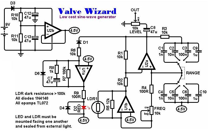
http://www.valvewizard.co.uk/siggen.html
This circuit uses an LDR that is in close proximity to an LED - essentially a DIY opto coupler. Since I do not have any LDRs on hand I was wondering what kind of modification to the circuit would be required so that I can use a regular opto coupler instead. The opto couplers I have on hand have a built in photo transistor.
Thanks.... -
The LDR circuit you show really requires a photoresistor, for two reasons:
1. The photoresistor (also a thermistor or light bulb) is a two-terminal symmetric device where I(-V) = -I(+V), not necessarily a linear function.
2. Photoresistors have a slow response to the light compared with phototransistors. This can be exploited as part of the control design. -
The LDR circuit you show really requires a photoresistor, for two reasons:
1. The photoresistor (also a thermistor or light bulb) is a two-terminal symmetric device where I(-V) = -I(+V), not necessarily a linear function.
2. Photoresistors have a slow response to the light compared with phototransistors. This can be exploited as part of the control design.
Thank you for this clarification.
OK, I breadboarded this last circuit and it works really well. This is in fact my most successful attempt at building a sine generator, so far. I am going to call this good and build a PCB for it.
This design even has one of my initial requirements, which is the use of a single gang pot.
There is, however, one detail that the designer describes, that I am not 100% clear on.QuoteAll this does have a down side; the tuning becomes roughly exponential. In other words, the frequency does not vary evenly as you vary the tuning pot. Ideally we would need a pot with an anti-exponential taper (good luck). As a compromise I used a log pot backwards, so turning it anticlockwise increases the frequency...
Wouldn't a better solution be to just buy a reverse log pot?
Thanks...
-
Log-taper pots are far easier to find, since they are the normal audio volume control. Turning ccw to increase frequency is a reasonable method. Cheap log-taper pots are not very accurate, so you need to carefully calibrate the dial. Accurate volume controls are usually stepped attenuators (totally unsuitable for your application) or stepped voltage dividers (which will work as a stepped resistor), which you may find awkward ( typically 24 steps).
-
Turning ccw to increase frequency is a reasonable method.
I think so too, because one could think of it as decreasing the wavelength. Although the dial would not actually be marked that way.Cheap log-taper pots are not very accurate, so you need to carefully calibrate the dial.
I can already see how this would be tricky to do so that it's accurate for every decade.
Perhaps it's more practical to just use a frequency counter that displays the exact frequency. Would that work?Accurate volume controls are usually stepped attenuators (totally unsuitable for your application) or stepped voltage dividers (which will work as a stepped resistor), which you may find awkward ( typically 24 steps).
My hope is to have a signal generator to test audio amps. What peek to peek voltage range should I have for that application?
Also, I see on Mouser that they have pots categorized as reverse audio and also as inverse log. Isn't that the same thing?
Thanks...