-
Hey Guys,
So as part of a project to build a Z80 Based Computer I am making my own EPROM Programmer. Just something that will easily put a hex file onto a ROM and then read off what it just wrote so that i can verify that it's all fine. I am using a raspberry pi to read from the hex file byte by byte, this is then sent over a serial port to an arduino that handles the programming. Two 74HC595 shift registers are handling the address BUS, and the data bus is directly linked to the Arduino. I've done various stages of testing, so I know that the serial connection, address section and data section of the system are working. The code seems to run fine when I execute it, however when I try to read from memory it just brings up all zero for every address. Can anyone help? I feel like it's an issue with the code as the connections on the breadboard seem fine. Here's the code:
Code for Reading:Code: [Select]/* This is the source file for the EPROM Programmer! The pin declarations in this file are specifically setup
* for the Arduino Micro, however you can modify the pins to fit your own Arduino Board. This code is paired with$
* script that sends the hex file byte by byte to the Arduino, which will then put it into the correct address of$
*
* The hardware for this programmer is two 74HC595 Shift Registers driving the address BUS, with the data BUS and$
* pins directly connected to the Arduino Pins.
*
* This is the version of the code used to READ from memory!
*
* For more information please visit my website at: [url=http://www.RCtalesofarookie.weebly.com]www.RCtalesofarookie.weebly.com[/url]
*
* Created by Sam Maxwell
* FEB 2016
*/
// Constant Variables that hold the pin values, please change these for your specific Arduino Board
// Variables for the 595 Shift Registers driving the address BUS
const int SRClock = 12;
const int Enable = 11;
const int RClock = 10;
const int SRIn = 9;
// Variables for control pins on the ROM
const int write_pin = 0;
const int mem_enable = 1;
const int mem_output = 14;
// Variables for Storing the current character, current byte and current address
int current_char;
int current_addr = 0;
// Main Code
// Setup
void setup(){
// Setting up the Serial Connection for debugging purposes, as well as programming status.
Serial.begin(9600);
Serial.println("Programmer Initialising!");
// Setting Pin Modes
for(int x = 14; x > -1; x--){
pinMode(x, OUTPUT);
}
digitalWrite(Enable, LOW);
digitalWrite(write_pin, HIGH);
digitalWrite(mem_output, HIGH);
digitalWrite(mem_enable, HIGH);
// Programmer Initialised
Serial.println("Programmer Initialised");
}
// Loop
void loop(){
// Setting Address on Address BUS
digitalWrite(RClock, LOW);
shiftOut(SRIn, SRClock, MSBFIRST, (current_addr >> 8));
shiftOut(SRIn, SRClock, MSBFIRST, current_addr);
digitalWrite(RClock, HIGH);
// Reading Values from Memory
digitalWrite(mem_enable, LOW);
digitalWrite(mem_output, LOW);
int a = digitalRead(13);
int b = digitalRead(8);
int c = digitalRead(7);
int d = digitalRead(6);
int e = digitalRead(5);
int f = digitalRead(4);
int g = digitalRead(3);
int h = digitalRead(2);
current_char = (a << 7) + (b << 6) + (c << 5) + (d << 4) + (e << 3) + (f << 2) + (g << 1) + h;
digitalWrite(mem_enable, HIGH);
digitalWrite(mem_output, HIGH);
// Printing Current Values
Serial.print("Current Byte:");
Serial.println(current_char);
Serial.print("Current Address:");
Serial.print(current_addr);
delay(40);
// Increasing Address Value
current_addr = current_addr + 1;
}
Code for Writing:Code: [Select]/* This is the source file for the EPROM Programmer! The pin declarations in this file are specifically setup
* for the Arduino Micro, however you can modify the pins to fit your own Arduino Board. This code is paired with$
* script that sends the hex file byte by byte to the Arduino, which will then put it into the correct address of$
*
* The hardware for this programmer is two 74HC595 Shift Registers driving the address BUS, with the data BUS and$
* pins directly connected to the Arduino Pins.
*
* This is the version of the code used for WRITING to memory!
*
* For more information please visit my website at: [url=http://www.RCtalesofarookie.weebly.com]www.RCtalesofarookie.weebly.com[/url]
*
* Created by Sam Maxwell
* FEB 2016
*/
// Constant Variables that hold the pin values, please change these for your specific Arduino Board
// Variables for the 595 Shift Registers driving the address BUS
const int SRClock = 12;
const int Enable = 11;
const int RClock = 10;
const int SRIn = 9;
// Variables for control pins on the ROM
const int write_pin = 0;
const int mem_enable = 1;
const int mem_output = 14;
// Variables for Storing the current character, current byte and current address
char current_char;
int current_addr = 0;
// Main Code
// Setup
void setup(){
// Setting up the Serial Connection for debugging purposes, as well as programming status.
Serial.begin(9600);
Serial.println("Programmer Initialising!");
// Setting Pin Modes
for(int x = 14; x > -1; x--){
pinMode(x, OUTPUT);
}
digitalWrite(Enable, LOW);
digitalWrite(write_pin, LOW);
digitalWrite(mem_output, HIGH);
digitalWrite(mem_enable, HIGH);
// Programmer Initialised
Serial.println("Programmer Initialised");
}
// Loop
void loop(){
if(Serial.available() > 0){
// Reading the Character from the Serial Port
current_char = Serial.read();
// Printing Character to Serial Terminal
Serial.print("Current Byte:");
Serial.println(current_char);
Serial.println(current_char, BIN);
Serial.print("Current Address:");
Serial.println(current_addr, BIN);
// Setting Address on Address BUS
digitalWrite(RClock, LOW);
shiftOut(SRIn, SRClock, MSBFIRST, (current_addr >> 8));
shiftOut(SRIn, SRClock, MSBFIRST, current_addr);
digitalWrite(RClock, HIGH);
// Setting the values on the data bus
digitalWrite(13, bitRead(current_char, 7));
digitalWrite(8, bitRead(current_char, 6));
digitalWrite(7, bitRead(current_char, 5));
digitalWrite(6, bitRead(current_char, 4));
digitalWrite(5, bitRead(current_char, 3));
digitalWrite(4, bitRead(current_char, 2));
digitalWrite(3, bitRead(current_char, 1));
digitalWrite(2, bitRead(current_char, 0));
// Writing Values into Memory
digitalWrite(mem_enable, LOW);
delay(100);
digitalWrite(mem_enable, HIGH);
// Increasing Address Value
current_addr = current_addr + 1;
}
}
EDIT: Oh and also here's a link to the memory datasheet: http://html.alldatasheet.com/html-pdf/316593/LYONTEK/LY62256PL/296/1/LY62256PL.html
Thanks for any help in advance!
Alberto -
Without a schematic?
Doubtful.
I don't know about everybody else, but my crystal ball broke decades ago. And my psychic ability leaves something to be desired.
Hardware the data bus at the EPROM so it'll read back a value different from all 0's and try reading again. Should read back whatever value you hard wire it to. -
Also that data sheet links to a static ram. What sort of eprom are you using?
-
Ah! That's why I didn't see anything pertaining to Vpp.
I thought my eyes were just being stupid. -
Hmm yes sorry, I'm being an idiot, missing out information in my post. I linked to a static RAM datasheet as I am using it to test before I program my actual OTPEPROMs. I could draw up a schematic quickly but I don't have one currently as I built it on a breadboard, didn't feel the need since there aren't that many connections and they aren't too complicated. That could be where the issue lies, but I feel like it might be something to do with the way I am driving the control pins on the memory itself. It's possible that the chip is not enabled correctly when I am trying to read from it, however I have checked the code and it seems fine.
I posted it just to see if someone else looking at it might spot anything, or if I am making a fundamental error. -
I linked to a static RAM datasheet as I am using it to test before I program my actual OTPEPROMs.
Whaaaaa???
A "One Time Programmable" "Erasable PROM"?
Which one is it?
What is the actual part number on the chip itself? -
Ok, my mind really escapes me, been working on this all day. It's an OTPROM, here's the datasheet: http://www.atmel.com/images/doc0014.pdf
-
This doesn't look right if you're trying to read D0-D7 back
// Setting Pin Modes
for(int x = 14; x > -1; x--){
pinMode(x, OUTPUT);
}
-
Doh! I'll amend that now and test it tomorrow morning. It's always harder to see your own mistakes.
I apologize for the lack of a schematic and for explaining it so badly in the initial post, I should learn some better forum etiquette. I am eager to get this working, as my computer is sat on the side waiting to be tested for the first time, we shall see how it goes!
Thanks for all the help again, although I may need more tomorrow morning if changing that code isn't the fix! :S
Alberto -
Think of what you need to do, make a list on paper.
Then think of the additional steps needed for each item of the list.
Keep breaking problem down until no more sub steps are needed.
For 74HC595 you need data then clock and repeat until data is in correct position. Then clock the latch. Enable output when output needed.
For ram from default state, put address on address inputs then enable cs
then,
For write put data on inputs then wr and wait,
or
For read OE and wait then read data.
then back to default state
A good test would be No Ram and use arduino's data buss to read 74HC595's outputs. The smart tester would note that the 74HC595's output could be low or high while the arduino's data buss was also programmed to be an output. To protect against this possibility would use resistors to connect the 74HC595's output pins of to arduino's data pins to limit current if one was high while other is low..
Changing what some of the resistors were connected to would then let arduino test other parts of the arduino program by doing extra arduino data bus reads.
-
Quote
For write put data on inputs then wr and wait
Ok that is also another mistake on my part, I should have looked at the timing diagram more carefully. I need to amend the code so that is sets the values on the data bus after the chip has been enabled, that was also an issue with the code. Having looked at the timing diagram for the read cycle again I can see that the output data is actually valid for a considerable amount of time even after #OE and #CE have gone high. Should I read the data after these the rising edge of these pins?
Plenty of mistakes, which is good. Better to learn now in my own time, and that's what this is about.
-
For write data before WR signal
For read, read data before change to tri-state which happens on OE going high
Did not look close but also check actions with 595 as listed previous message.
-
Ok, my mind really escapes me, been working on this all day. It's an OTPROM, here's the datasheet: http://www.atmel.com/images/doc0014.pdf
Ya know, you could re-run two wires and use a 28x256 EEPROM instead. In fact, there's plenty of 28 pin DIP package 32Kx8 EEPROMs out there with almost the same pinout, basically the same method of operation, AND they don't need the odd +12v/+25v programming voltage.
Also while I'm thinking about it...
An unprogrammed EPROM's cells are 'filled' with $FF, whereas a fully progammed EPROM (if programmed with all 0's) would readback all 0's.
In an EPROM, you can change a 1 to a 0, but you can't change a 0 to 1.
It's entirely possible that the One-Time Programmable PROM is already fully programmed. -
This sounds like a stupid question, but is the programming voltage for these OTPROM's 12v? I can't seem to find an exact figure anywhere on the datasheet, however it says that it can't go above 14v, so I'm assuming that's the case.
As I said previously, I haven't tried to program one of the ROM's yet as I want to test the system with RAM first before I waste one of my OTPROM's. I was told that it was a good idea to test with RAM first, I just need to maintain power to it through the whole test. -
Ok, so I've got something that looks like a modicum of progress. I have written data to the the RAM, and when I run the read program some data does come back over the serial port. However the data that comes back bares little resemblance to what I'm writing to the RAM. What does strike me is that as I decrease the time delay between each cycle the data changes, could it be something to do with the data being read when it's invalid?
-
No, but if you would post an actual schematic or at the very least a picture of the PCB, we might have a better guess at what's going on. Otherwise, its still a guessing game at best.
-
Quote
No, but if you would post an actual schematic or at the very least a picture of the PCB, we might have a better guess at what's going on. Otherwise, its still a guessing game at best.
Apologies again, Im not great at this.
Here's the schematic (It's extremely crude...):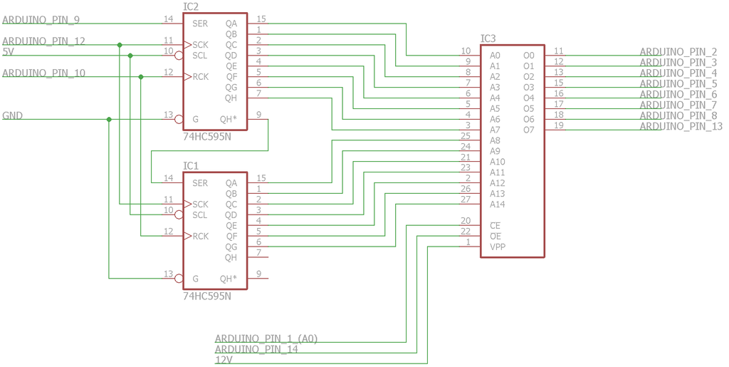
At the moment there is an additional Arduino Pin (Pin 0) connected to drive the write enable pin for the SRAM. I hope the schematic gets across what I'm trying to do, the issue is I don't really want to spend a lot of money on an EPROM Programmer when I'm probably not going to use it an awful lot. -
Do you want to post your latest code as we know the code in post #1 is buggy as pointed out by me and C
-
Apologies again, Im not great at this.
Something is better than nothing.
If that schematic is accurate, then there is one major thing that stands out immediately.
Decoupling cap's. Where are they?
-
Quote
Decoupling cap's. Where are they?
Hmmmm, I don't know what's wrong with me this week. I'll add one now. Do you think that's what could be causing the instability in the data that I am reading?QuoteDo you want to post your latest code as we know the code in post #1 is buggy as pointed out by me and C
Sure thing, here you go:
Code for Reading:Code: [Select]/* This is the source file for the EPROM Programmer! The pin declarations in this file are specifically setup
* for the Arduino Micro, however you can modify the pins to fit your own Arduino Board. This code is paired with$
* script that sends the hex file byte by byte to the Arduino, which will then put it into the correct address of$
*
* The hardware for this programmer is two 74HC595 Shift Registers driving the address BUS, with the data BUS and$
* pins directly connected to the Arduino Pins.
*
* This is the version of the code used to READ from memory!
*
* For more information please visit my website at: [url=http://www.RCtalesofarookie.weebly.com]www.RCtalesofarookie.weebly.com[/url]
*
* Created by Sam Maxwell
* FEB 2016
*/
// Constant Variables that hold the pin values, please change these for your specific Arduino Board
// Variables for the 595 Shift Registers driving the address BUS
const int SRClock = 12;
const int Enable = 11;
const int RClock = 10;
const int SRIn = 9;
// Variables for control pins on the ROM
const int write_pin = 0;
const int mem_enable = 1;
const int mem_output = 14;
// Variables for Storing the current character, current byte and current address
char current_char;
int current_addr = 0;
// Main Code
// Setup
void setup(){
// Setting up the Serial Connection for debugging purposes, as well as programming status.
Serial.begin(9600);
Serial.println("Programmer Initialising!");
// Setting Pin Modes
pinMode(0, OUTPUT);
pinMode(1, OUTPUT);
pinMode(14, OUTPUT);
for(int x = 12; x > 8; x--){
pinMode(x, OUTPUT);
}
pinMode(13, INPUT);
for(int y = 8; y > 1; y--){
pinMode(y, INPUT);
}
digitalWrite(Enable, LOW);
digitalWrite(write_pin, HIGH);
digitalWrite(mem_output, HIGH);
digitalWrite(mem_enable, HIGH);
// Programmer Initialised
Serial.println("Programmer Initialised");
}
// Loop
void loop(){
// Setting Address on Address BUS
digitalWrite(RClock, LOW);
shiftOut(SRIn, SRClock, MSBFIRST, (current_addr >> 8));
shiftOut(SRIn, SRClock, MSBFIRST, current_addr);
digitalWrite(RClock, HIGH);
// Reading Values from Memory
digitalWrite(mem_enable, LOW);
digitalWrite(mem_output, LOW);
int a = digitalRead(13);
int b = digitalRead(8);
int c = digitalRead(7);
int d = digitalRead(6);
int e = digitalRead(5);
int f = digitalRead(4);
int g = digitalRead(3);
int h = digitalRead(2);
delay(2);
current_char = (a << 7) + (b << 6) + (c << 5) + (d << 4) + (e << 3) + (f << 2) + (g << 1) + h;
digitalWrite(mem_enable, HIGH);
digitalWrite(mem_output, HIGH);
// Printing Current Values
Serial.print("Current Byte:");
Serial.println(current_char);
Serial.print("Current Address:");
Serial.println(current_addr);
delay(1);
// Increasing Address Value
current_addr = current_addr + 1;
}
Code for Writing:Code: [Select]/* This is the source file for the EPROM Programmer! The pin declarations in this file are specifically setup
* for the Arduino Micro, however you can modify the pins to fit your own Arduino Board. This code is paired with$
* script that sends the hex file byte by byte to the Arduino, which will then put it into the correct address of$
*
* The hardware for this programmer is two 74HC595 Shift Registers driving the address BUS, with the data BUS and$
* pins directly connected to the Arduino Pins.
*
* This is the version of the code used for WRITING to memory!
*
* For more information please visit my website at: [url=http://www.RCtalesofarookie.weebly.com]www.RCtalesofarookie.weebly.com[/url]
*
* Created by Sam Maxwell
* FEB 2016
*/
// Constant Variables that hold the pin values, please change these for your specific Arduino Board
// Variables for the 595 Shift Registers driving the address BUS
const int SRClock = 12;
const int Enable = 11;
const int RClock = 10;
const int SRIn = 9;
// Variables for control pins on the ROM
const int write_pin = 0;
const int mem_enable = 1;
const int mem_output = 14;
// Variables for Storing the current character, current byte and current address
char current_char;
int current_addr = 0;
// Main Code
// Setup
void setup(){
// Setting up the Serial Connection for debugging purposes, as well as programming status.
Serial.begin(9600);
Serial.println("Programmer Initialising!");
// Setting Pin Modes
for(int x = 14; x > -1; x--){
pinMode(x, OUTPUT);
}
digitalWrite(Enable, LOW);
digitalWrite(write_pin, HIGH);
digitalWrite(mem_output, HIGH);
digitalWrite(mem_enable, HIGH);
// Programmer Initialised
Serial.println("Programmer Initialised");
}
// Loop
void loop(){
if(Serial.available() > 0){
// Reading the Character from the Serial Port
current_char = Serial.read();
// Printing Character to Serial Terminal
Serial.print("Current Byte:");
Serial.println(current_char);
Serial.println(current_char, BIN);
Serial.print("Current Address:");
Serial.println(current_addr, BIN);
// Setting Address on Address BUS
digitalWrite(RClock, LOW);
shiftOut(SRIn, SRClock, MSBFIRST, (current_addr >> 8));
shiftOut(SRIn, SRClock, MSBFIRST, current_addr);
digitalWrite(RClock, HIGH);
// Writing Values into Memory
digitalWrite(13, bitRead(current_char, 7));
digitalWrite(8, bitRead(current_char, 6));
digitalWrite(7, bitRead(current_char, 5));
digitalWrite(6, bitRead(current_char, 4));
digitalWrite(5, bitRead(current_char, 3));
digitalWrite(4, bitRead(current_char, 2));
digitalWrite(3, bitRead(current_char, 1));
digitalWrite(2, bitRead(current_char, 0));
digitalWrite(mem_enable, LOW);
digitalWrite(write_pin, LOW);
delay(4);
digitalWrite(write_pin, HIGH);
digitalWrite(mem_enable, HIGH);
// Increasing Address Value
current_addr = current_addr + 1;
}
}
Hope this helps! -
Hmmmm, I don't know what's wrong with me this week. I'll add one now. Do you think that's what could be causing the instability in the data that I am reading?
Yep. The instantaneous current draw of a write can cause a heck of a sag in the power rail...at the chip...and cause the wrong data to be written, if it's written at all.
A smattering of .1uF caps across various powers/grounds will do no harm.
And the wires themselves are another story. If you've got a foot of wire for each connection, well, you're just inviting problems.
As far as your '595 set up...I'd be putting some LEDs on those output pins and making sure the pins are doing what you think they're doing vs. what you want them to do.
eg. LEDs on the data pin, write all ones to the pin, all the LEDs light up. Write a 10101010, every other LED lights up, and so on.
Same thing goes for reading. As mentioned before, hard wire the input pins to a specific combination, eg. 10101010, and see what you read back. And try various combinations until you're satisfied that you're '595 and inputs are working correctly.
In fact, tie the '595 outputs directly to the inputs (thru a resistor of course).
If you write something out, you should read the same thing back.
Get that SRAM (OTPROM, whatever) out of there for now.
Break it down. Build it back up. -
I was just typing a very similar response to Skimask about testing in stages. Also I have an observation: I'm not familiar enough with ardruino to know how these get glued together, but if you have to setup all the pin directions each time that probably means that your pins are going high Z between writing and reading. And that means that WR, CS OE etc of the memory aren't defined. And that means there is a chance of corruption of RAM during those transitions. Add pull-ups to CS, WR and OE of your RAM to put it into a well known state when ardruino isn't driving it.
-
In terms of testing things individually, I have already tested the address lines with LED's and I've tested the output of the data lines with LED's. I need to test the read functionality, so I will do that before I do anything else.
EDIT: Just saw rich's post, will also make that change. -
Ok, I've tested the read cycle by inputting the first eight bits of the address BUS into the data BUS. The system is reading correctly and the bitwise operators are also working correctly. The inputs replicate the outputted values on the address BUS. Here's an image:
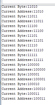
So it seems like everything to do with the program and address BUS hardware is working correctly. I will run a test again and see what happens... -
Ok so I've run the test on the full system, and the data still does not match the data I am trying to write to the SRAM. What is slightly strange is that there seems to be some sort of recurring pattern in the data that is being read back. Whether or not that is just me looking for something that isn't there, or whether it actually means something, is another matter.
Here's an image of the data I am getting back: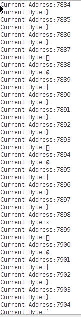
I can't make sense of this, possibly I am reading the data before it's valid?