Hi,
I am not a home at the moment, but I think it was a 27134PDLA Hammond / Eddystone series box.
If you wait until monday I can look it up to be 100% sure.
Regards
Wolfgang
Thanks,
As the 27134PDLA is not available at Digikey/Mouser, I will fit it in the dimensionaly similar 1590T.
About the Fuse: I have selected LittleFuse 0251001.NRT1L . Does the series resistance (0.128 Ohms) affects the circuit?
About the injection resistor, I have seen documentation claiming the resistor must match the transformer impedance. Picotest’s J2101A recommend a 5 Ohm resistor. What do you recommend?
As seen in the rest of this thread -- lower load resistance extends LF response, at greater expense to the HF response. HF response is most when source and load are matched; but you may not need this range, so that may be an acceptable tradeoff.
The load resistance is usually made low so that it does not interfere with the circuit it's introduced to.
Tim
Thanks,
As the 27134PDLA is not available at Digikey/Mouser, I will fit it in the dimensionaly similar 1590T.
About the Fuse: I have selected LittleFuse 0251001.NRT1L . Does the series resistance (0.128 Ohms) affects the circuit?
About the injection resistor, I have seen documentation claiming the resistor must match the transformer impedance. Picotest’s J2101A recommend a 5 Ohm resistor. What do you recommend?
Hi,
I bought mine at Conrad electronics (I found an old email). I dont know if you have something similar in Canada. The box does not really matter. Now for the fuse: The allowable DC current for the high-mu cores is very small, in the range of 10mA. The fuse is just there to prevent destructions by dead shorts. The wire resistance of the windings is a few 100Ohms so I see no issue with the fuse resistance. In total we are way below 1Ohm.
best regards
Wolfgang
I just did mine,
Here's the BOM, using Mouser parts:
2x 983-T60006-L2030W514
2x 576-0251001.NRT1L
1x 546-1590T
1x 530-108-0903-1
1x 530-108-0902-1
1x 571-5-1634523-1
1x 71-AVE030020E16R0KE
optionnal: 1x 372-U1163A
I used less than 3m of twisted pair wire from a CAT7 patch chord I had laying around.
Total cost: 95 Canadian $.
Did not test yet, but posting to share the love.
Thanks again Wolfgang!
Cool ! The little green things are fuses, am I right ?
Curious for the measurements now, of course !!
Regards
Wolfgang
Thanks, I've already seen tham. Good site !
Curious, what's the rating on the fuses that you used? I'd assume it's fairly large (>1A) as we're only trying to prevent wires from over-heating during transformer saturation.
Hey guys
I finally got around using the thing.
I installed the demo of Frequency Response Analysis option for the DSOX3000T scope. It uses the onboard signal generator and scope probes to do the magic.
To qualify my NVT-1, I plugged a BNC from the WaveGen to the VNT-1 Input, and both scope probes to the VNT-1 output.
Looks like a pretty flat response!
I attached the image of the plot, setup, and the .CSV of the results.
@MilkmanCDN: I Used 1 Amp fuses. See Mouser part#.
Curious, what's the rating on the fuses that you used? I'd assume it's fairly large (>1A) as we're only trying to prevent wires from over-heating during transformer saturation.
Yes, I used a few 100mA IIRC. The purpose is to prevent buring the wires. The core will saturate way before that will happen.
Hey guys
I finally got around using the thing.
I installed the demo of Frequency Response Analysis option for the DSOX3000T scope. It uses the onboard signal generator and scope probes to do the magic.
To qualify my NVT-1, I plugged a BNC from the WaveGen to the VNT-1 Input, and both scope probes to the VNT-1 output.
Looks like a pretty flat response!
I attached the image of the plot, setup, and the .CSV of the results.
@MilkmanCDN: I Used 1 Amp fuses. See Mouser part#.
Looks fairly flat and OK to me ! And now much fun with the virgins !

I finally got mine wound up and made a signal splitter for my HP 3577A. Still, I need to add some AC coupling on the inputs.
I think I am now set up for a new SMPS design I am building.
rx8pilot:
For building up some confidence in the cal and measurements procedures, I'd recommend to rebuild the HP35676A test set:
http://hparchive.com/Manuals/HP-35676-SCHEMATIC.pdf
No need for all the fancy metalwork, and don't worry about the unknown capacitor, it still works built on a piece of SMT protoboard using some MiniMelf resistors (some of the series connected to get near the original value).
Once calibrated using the full cal procedure (again, no need for a fancy cal standards set, a wire and a 50 Ohm resistor works, you'll get some ripple at the 200MHz end), then switching the 3577A to impedance display (choose "F4" as the input to display , it's written somewhere in the manual), you can get impedance sweeps of known components (start with resistors in the 10 Ohm to k Ohm range) and get familiar with the way it works. Measure some inductors and capacitors, read the imaginary part at some frequencies and do the math to verify your reading. Inductors are quite fancy regarding their impedance over frequency, many of them are inductors at rather low frequencies only.
There's also somewhere a manual on the net (for this or the HP35677 test set) that has a better description of how to measure impedance using the 3577A than the 3577A manual.
Edit: Found it, here it is: https://cb.wunderkis.de/wk-pub/Keysight%2035676A%20Data%20Sheet.pdf
Edit 2: Don't know what you mean by "skewed", the manual has some tips regarding the RBW setting: Reverse the sweep direction and watch if the graph shifts. If it does, your sweep speed is to fast for the chosen RBW.
Edit 3: "F4" is impedance for a 50 Ohm system and calibration, "F5" is for 75 Ohm
Hi
I had planed to rebuilt the HP 35676 but I have some questions regarding it's operation as described in the manual.
First of all, if I look at this schematic, it seems to me that the 80R6 is the current sensing shunt resistor. The rest is pretty much a ~13dB T-attenuator for the reference input and a ~9dBm T-Attenuator on the voltage sensing A input. At least that is what I first thought.
But when I read the manual, I see that for one port measurment the A/R and for 2-port the B/R functions are applied. So this would mean measurements of "V" "only"(?) In this case I assume the 80R6 resistor is used to match the two T-Attenuators which don't seem to have a 50ohms input impeadance on their own.
But, what if one would like to do V/I measurments? Could I use the 80R6 resistor as a shunt like I first thought and measure voltage over the DUT on the A port, and current trough the DUT via R-B measurment and terminate the DUT either in 50ohms / B input for a 50Ohm system or lets say at ground for a capacitor / inductor with =/ 50ohms?
Don't know if I can answer your question to your satisfaction. Afaik, the 35676 is just a voltage divider (the said 80R6 vs. the input impedance of the DUT). So the 3577 can measure the ratio of A to R and calculate the DUT's impedance within a limited range. There's no way to directly measure the current through the DUT.
Folks,
I finally finished putting my isolation transformer together. Took a little longer than I would have liked, and Dave is bang on regarding $500 being an acceptable price. Researching/purchasing all the right bits/pieces, winding the transformer, and testing took me quite a few hours.
My bill of materials is:
- Fuse Holder - $3.99 USD (10 pieces)
- Slow Blow Ceramic Fuse Kit - $7.98 USD
- 1590B Guitar Stomp Box - $4.24 USD
- Wiring Terminal (for chassis ground) - $18.90 USD (10 pieces)
- Adhesive Insulation Foam (10mm thick) - $1.80 USD (1 sheet)
- Red/Black Banana Socket - $3.66 USD (includes 5x Red and 5x Black)
- Insulated BNC Connectors - $4.85 USD (10 pieces)
- CAT6a Ethernet Cable (14 ft) - ~$10 USD
- I had one of these lying around. I cut the ends off and used. 23AWG stranded wire.
- Blue Paint - ~$7 CAD
- Not required, but I picked up a can of metal spray paint from Home Depot.
- Transformer Vaccumschemelze T60006-L2040W424- ~$40 USD
- Avery Sticker Sheets (6468 template) 2"x 4" Labels - ~$10 USD
- I had some of these lying around.
I reduced the cost of the transformer by building multiple (x3) as a couple of friends wanted one. I estimate that the cost of materials to construct is around ~$65 - $80 USD per transformer. I've got around 10-20 hours into this project.
I've attached a copy of the Visio diagram that I used to create both the drill templates and stickers.
Pictures of the unpainted metal boxes, drilled boxes, internal components, and finished transformers are attached. I decided to call the transformer ANVT-100 as a play on Dave's review. I did test these transformers using a scope/function-generator and performance is right in line with what has been previously posted here. When I get a chance, I'll circle back and post a proper bode plot from the Venable at the office.
A big thanks to all on this forum. Especially Wolfgang and DualTriode for sharing their build and test details. Lot's of great information here and really helpful folks.
Chapeau ! Looks VERY close to the original. I find my nude virgin label more attractive, however.
Why you have just *one* fuse ?
Wolfgang
Thanks Wolfgang,
I only put one fuse because it's typically the driving side (BNC input) that injects current. However, given that the transformer could be used in both directions, and the secondary can also be subject to higher currents, I suppose putting one on both sides would be prudent. That said, the original BWIT-100 only has a fuse one-side as well.
I also think your label is much more attractive; however, it's resemblance to a famous internet meme (think goats), might get the box banned from my household. I'm pretty sure my wife wouldn't approve.
... in the end, its a classic piece of art by Modigliani recently sold for more than 100 million at Sotheby's.
Its undisputably *art*, nothing else. Be strong and defend the liberty of free expression !!

You know what: an engineer from Omicron had a burst of laugh when he saw it - these people are OK, and their sense of humour is OK too.
You know what: an engineer from Omicron had a burst of laugh when he saw it - these people are OK, and there sense of humour is OK too.
That is my impression of them, too.
... in the end, its a classic piece of art by Modigliani recently sold for more than 100 million at Sotheby's.
I see what you did there.
Honi soit qui mal y pense.

Hi group,
I see a lot of people have winding their own NVTs. I want to share an alternative approach.
You simply buy the B82720H0015A035 EPCOS (TDK) from Digikey. They cost $2.66 USD or $3.66 CDN.
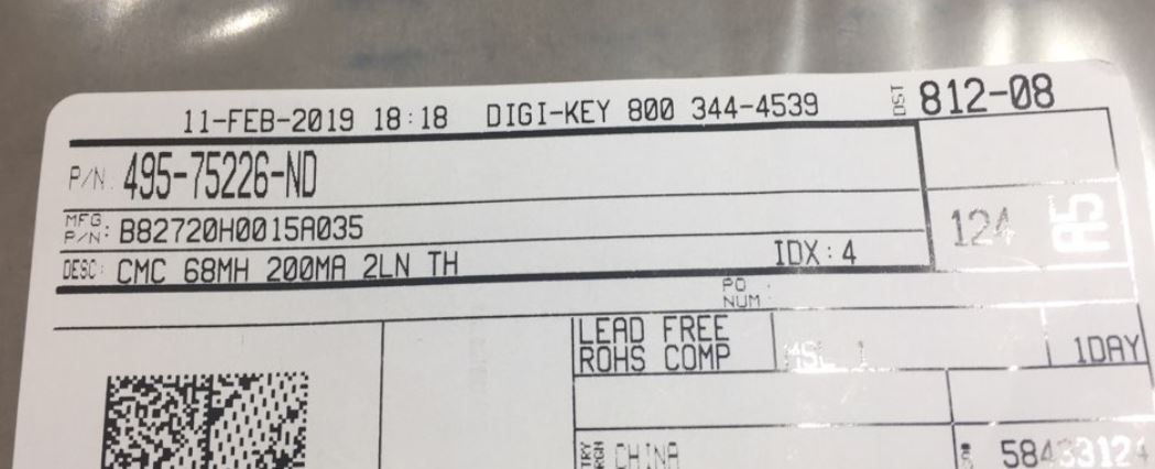
This part is quite small:
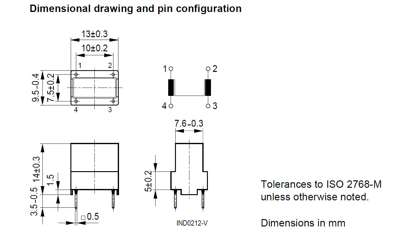
Here is the spec:

The magnetizing inductance is 68mH, not as high as the NVTs, but still quite high. The leakage (stray) inductance is 1200nH.
In a 50

test circuit:

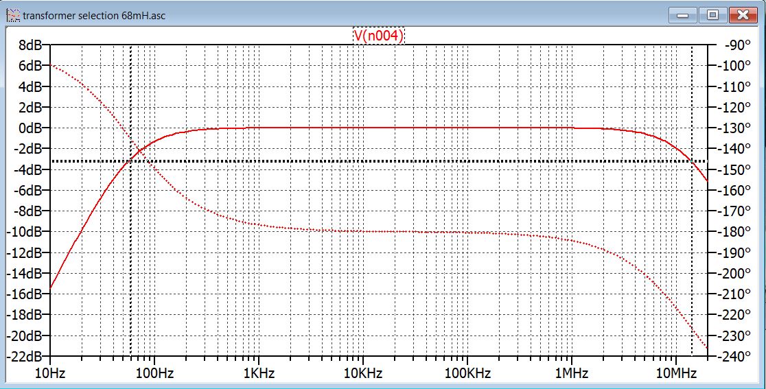
The modelling results show a 3dB bandwidth from 60Hz to 13 MHz.
The model does not include any capacitance.
Measured results:

The low frequency 3dB point is 50 Hz
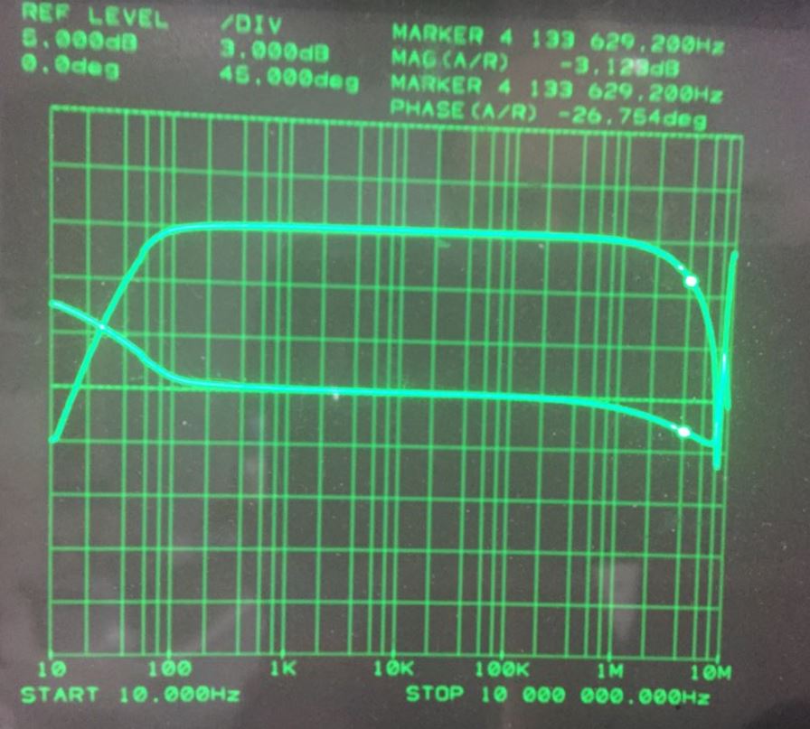
The high frequency 3dB point is 4MHz.
The transformer does not have to be flat in the normal control loop measuring scheme.
This common mode choke, used as a transformer, is suitable for most power supply control loop analysis.
Regards,
Jay_Diddy_B
Hi,
why not ? If you can live with the bandwidth restrictions, its a cheap alternative. The cores I used cost some 10€ each.
Thanks !
Wolfgang