-
Fundamentals Friday
Dave explains what the ripple and noise specifications on a power supply is and how to measure it using different methods on both analog and digital oscilloscopes. From bad techniques through to good, showing the effect of each one. Traps for young players aplenty in this one.
How do you detect common mode noise issues and ensure that the signal you are measuring is really coming from your device under test?
Single ended & differential measurement, DIY coax solutions, termination, analog vs digital oscilloscopes, bandwidth limiting, and even oscilloscope probe coax construction issues. It's all here.
Mysteries of X1 oscilloscope probes revealed:
How to track down common mode noise:
Opamp Noise voltage tutorial:
-
Nice t-shirt!
-
Fundamental Friday on Thursday. Must be back to the future!
-
Great didactical way from the "normal" probe to the DIY differential probe.
Big That's for sure.
-
In ATX specifications they recommend measuring the ripple by placing a 10uF electrolytic as close as possible to the probe tip and ground and setting the scope on 20 Mhz as you did.
I guess it would be as a sort of filter for the noise in the leads from the power supply to the connector at the end of the leads?
If you have time, it would be great if you could make a video about how to measure the current ripple a capacitor would be subjected to.. lately I've seen a blog on Corsair's site saying that their primary capacitor is often subjected to current ripples much higher than the rating of the capacitor, but they use them like that anyway due to size constrains. It's not very clear to me how one measures the current ripple in a capacitor. -
Post of a Preamble 1855 (now lecroy) diff amp feeding a Tek 2225 here measuring PSU ripple.
Post of a Tek 7A22 diff amp in a 7603 mainframe measuring <40µV PSU ripple here
Another good technique is to connect all your probing and connections to the PSU with the PSU turned OFF. Whatever you are seeing on your scope is ambient noise getting into your measurement setup. This allows you to tweak your setup without getting fooled. -
Another good technique is to connect all your probing and connections to the PSU with the PSU turned OFF. Whatever you are seeing on your scope is ambient noise getting into your measurement setup. This allows you to tweak your setup without getting fooled.
Yes, but not foolproof. That likely wouldn't have caught that 142Hz from the electronic load. -
Another good technique is to connect all your probing and connections to the PSU with the PSU turned OFF. Whatever you are seeing on your scope is ambient noise getting into your measurement setup. This allows you to tweak your setup without getting fooled.
Yes, but not foolproof. That likely wouldn't have caught that 142Hz from the electronic load.
Completely agree. -
There goes all used differential probes at the market, all their prices will be sky-rocketed.

-
There goes all used differential probes at the market, all their prices will be sky-rocketed.
The EEVBlog, all care, but no responsibility taken
-
Lucky me, scored this "last year" under 50 bucksThere goes all used differential probes at the market, all their prices will be sky-rocketed.
The EEVBlog, all care, but no responsibility taken , bragging my so called "Jim Williams" differential probes.
Expecting a massive ebay snipers get armed for the word "differential probe" by the mob, hurry folks.
-
Hi,
I am going to contribute the technique that I use for measuring power supply ripple and noise. HP used to the term PARD, meaning Periodic And Random Disturbances.
This is the schematic:
The setup:
A photograph of the DC block, you can also see the 50 ohm series termination at the end of the coax. Tis soldered directly across the output capacitor:
This setup ensures a 50 Ohm measurement environment. The output from the power supply is very much less than 50 Ohms so we need the series termination resistor to prevent reflections in the cable. The spikes may have frequency content in 100-300 MHz range.
Jay_Diddy_B
-
For reference, the method recommended to measure ATX PSUs:
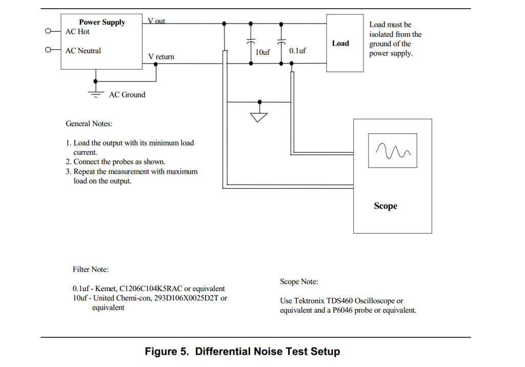
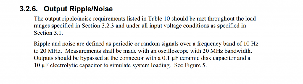
Source: http://www.formfactors.org/developer/specs/ATX12V%20PSDG2.01.pdf
(surprised they recommend very specific Tek scope/probes and caps)
[edit: added details] -
These kinds of measurements are one reason I keep a 7000 series Tektronix analog scope around. With a 7A22 differential amp plugin, this type of stuff is easy to measure.
This plugin goes down to 10 uV per division, so it is hard to beat for looking at really low level signals. Only 1 MHz bandwidth, though.
I use it quite a lot for checking the output from strain gages when building transducers. No other signal conditioning needed, just a DC excitation source. -
Lucky me, scored this "last year" under 50 bucks
, bragging my so called "Jim Williams" differential probes.
...
Nice score .. according to the spec I posted earlier, these are The probes of choice for the job
-
(surprised they recommend very specific Tek scope/probes and caps)
If its the P6046 is what you're talking, I guess it is a proven design and was quite popular back then when CRT scopes still roamed the earth. So popular since it was 1st launched at late 60s, and was still actively produced until in the 90s, and a brand new probe with the amplifier was priced about $1300 back in year 1989, and its equivalent to $3500 in today money. (Reference -> Tektronix P6046 history)
Probably its like a semi de-facto standard and was mentioned almost everywhere at old literatures when it comes to measurement at a scope using differential probe. -
Thanks, it was this reading below that sparked my interest in this particular probe for the 1st time.Lucky me, scored this "last year" under 50 bucks
Nice score, bragging my so called "Jim Williams" differential probes.
... .. according to the spec I posted earlier, these are The probes of choice for the job
It took me for a very-very long time and patiently waited & lurked for a good deal at ebay, it was not easy.
-
If its the P6046 is what you're talking, I guess it is a proven design and was quite popular back then when CRT scopes still roamed the earth. So popular since it was 1st launched at late 60s, and was still actively produced until in the 90s, and a brand new probe with the amplifier was priced about $1300 back in year 1989, and its equivalent to $3500 in today money. (Reference -> Tektronix P6046)
Probably its like a semi de-facto standard and was mentioned almost everywhere at old literatures when it comes to measurement at a scope using differential probe.
No doubt they are the reference model in the world of differential probes. I was just surprised an official document would note a recommendation on scope model and probes to use for a specific measurement
Would be great if you could do a comparison between the p6046 and analog Add/Inv and/or digital math sub. I think it would be interesting to see how much extra detail is obtainable with a proper set of diff probes vs. using 2 channels.
-
I'd tie the grounds of the two coaxes together at the measurement end since the return current has to go back to the scope otherwise. That is probably less important if 20 MHz is all you are measuring. The series terminations at the measurement end can be omitted as the scope should be a good match and not reflect much. The coax DC blocks are nice since you can get the ground loop even smaller on the board by omitting the capacitor.
For measuring power supplies on boards, I like to remove a decoupling cap and solder coax there. Or, alternately, do as Xilinx does on some dev boards and include a footprint for a coax connector to each power plane. -
Instead differential amplifier why not using balun with DC block on input side?
there is 50kHz ~ 200MHz balun with quite flat frequency respond.
-
rather weird this was published today, the day i almost burned the ground clip lead of my hameg hm307 scope measuring the ripple on pc psus.
also interesting in the context of
(EEVblog #279 - How NOT To Blow Up Your Oscilloscope! )
current did flow (to the point of starting to melt ground clip wire of the scope...luckilly i don't see any damage to the scope...or psu) when i (by mistake) touched ground clip to +12V output of psu.
wall outlet that was used (to power both scope and pc psu) doesn't have earthing contact.
that's what the eevblog 279 lacks, description of floating ground dangers...
(when both devices are plugged in the wall socket, continuity exists between psu metal case and ground of the scope, which means that 12V output was shorted for a brief period via that scope ground clip...)
mesuring itself was much easier than i thought it would be, crappy/worn psus producing more ripple/noise than good ones even on light loads such as 12v car light bulb of 60w (or 21w, for that matter), as without load there's nothing to measure, it's always perfect dc...unless caps are totally blown and then feedback shuts down the primary switch circuit as soon as you turn the psu on....
much easier than i thought by reading (and participating) in the previous discussion on badcaps and jonnyguru forums...
(offcourse my aim was never to get a ueber vertical resolution of that noise..i was just wondering on how visible it is on psus that are starting to malfuncion, ie to damage motherboards they power...i just hooked the scope to the output of the psu with that bulb as a load) -
Hi,
I have two questions which somewhat related to this topic.
How much is the noise and ripple effect to a mixed signal PCB.
Say a precsion ADC and a few digital logic block (SPI etc).
If I separated the Vddd (powered by SMPS) and Vdda (powered by Linear PS),
the noise and ripple should't effect the ADC (50SPS)right?. How much an effect has the SMPS
to the digital block , SPI running at 20Mhz?
Secondly has the noise and ripple ex.200mVpp has an effect on a constant load?
For example 12 Vout through a 100 ohm ..so will 2mA of extra current will be flowing through the resistor?
-
This video also have a lot problems with the autofocus of your camera.

You got a new camera, Dave? Or you changed something? Is the camera now with a new mount moved closer to the device?
Something changed, that's for sure! -
I think it has more to do with that Ultravision feature of the scope, which fades the graph so the camera tries to focus on it from time to time.
-
Also in the video "#592 Mailbag" you can see it. The autofocus is slower now.
-
I understand that having a 20MHz limit on noise makes it easier to compare one supply against another, but there are plenty of cases where higher frequency noise is a real factor. Many high-current SMPSUs intended for radio work even have an adjustment to tweak the switcher's frequency so you can move noise spurs if the power supply's causing interference at a sensitive point. and given that modern devices can switch really sharply there's a good chance that significant energy can be produced well into the hundreds of MHz.
Is there any good reason in general to deliberately filter out this sort of signal when trying to characterise a PSU's performance? I've certainly had problems in the past where a PSU's been generating enough high frequency crud to affect not only devices it's been powering, but through radiation from power cables has caused interference to other stuff in the general vicinity. There are a lot of Wun Hung Lo power bricks which are totally incontinent at RF, and pretending that anything above 20 MHz doesn't matter does no favours to anyone. It's no longer the case that this sort of bandwidth limitation is common to scopes, so it seems counterproductive to continue to mandate it as a standard.
-
As always, there's measuring power supply noise to conform to some arbitrary standard to put in a specification, and then there's testing for some specific purpose. If you know your device has some specific needs not covered by the usual test bandwidth, you'll need to do your own testing.
Also, be careful wih the 50 ohm terminators. Those things have power ratings too, and most of them can overheat if you are testing a powerful supply on higher voltage settings. Especially the ones that are built into scopes often can only tolerate a few volts, or they'll overheat. They're usually made for good high frequency response on small signals, not for handling high current. -
We recently bought few used DA1855A differential amplifiers that Dave mentioned in the video. I had to open one to fix the fan and I made some photos. I will post them soon. The input stage looks really interesting.
-
there are plenty of cases where higher frequency noise is a real factor
You are probably right, but remember how hard it is to carry high frequency signal because of small parasitic capacitance and inductance elements. Wires are inductors. Power supply wires are usually close to each other - capcacitor. you put 1 nF filter cap and you probably reduced 20+ MHz noise by factor of 10 to 1000. And you always have decoupling caps in your circuit. So most probably higher frequencies won't be a problem. If you try to filter 50 Hz - you need big heavy inductors and big capacitors.
Also higher frequencies are easier to pick up wirelessly. So unless your project is in good thick metal cage there will be more comming from the air rather than the power supply itself. -
ow. forgot - Dave, thanks for the video. I don't watch TV at all. I replaced it with youtube. At least you get something valuable from videos like this...
Wouldn't anyone suggest a schematic for 10x differential amplifier for measuring power supply ripple/noise voltage. I know the real differential amplifiers are expensive for a reason, but up to 20 MHz it shouldn't be that hard to have something that's good enough for hobby electronics. -
Wouldn't anyone suggest a schematic for 10x differential amplifier for measuring power supply ripple/noise voltage. I know the real differential amplifiers are expensive for a reason, but up to 20 MHz it shouldn't be that hard to have something that's good enough for hobby electronics.
A x10 single ended up amp would likely be adequate and useful for the task. 20MHz bandwidth is do-able with stock opamps. Differential is a different beast. -
This video also have a lot problems with the autofocus of your camera.
You got a new camera, Dave? Or you changed something? Is the camera now with a new mount moved closer to the device?
No, probably just me forgetting to select manual focus. Scope screens can really screw up the focusing. -
Also, be careful wih the 50 ohm terminators. Those things have power ratings too, and most of them can overheat if you are testing a powerful supply on higher voltage settings. Especially the ones that are built into scopes often can only tolerate a few volts, or they'll overheat. They're usually made for good high frequency response on small signals, not for handling high current.
Yes indeed, forgot to mention that one. No problem if you have an AC coupling cap right at the test point though. -
Is there any good reason in general to deliberately filter out this sort of signal when trying to characterise a PSU's performance?
It looks better on the spec sheet
As someone else mentioned, if you have specific requirements then you have to test the suply yourself under your own conditions. No way any spec spec can have enough load/bandwidth figures to cover everything. -
Dave
Why didn't you simply tie the ground of the scope to the PSU ground to reduce the CM burden placed on the scope?
Also, I use a high permeability toroid (Philips 3E5 mix) on the scope probe lead right at the scope input to reduce the CM noise. It makes a big difference to HF noise. It was standard practice on the scopes in our switchmode R&D lab.
Placing a second screen using coax braid (grounded at the scope side) over the scope lead from the instrument to the probe head should make a substantial difference also as the scope probe lead braid is generally pretty loose weave allowing radiated noise to become common mode noise on the leads.
Great video. I really look forward to these gems. Keep them coming.
Dick -
Couldn't a notch filter be used to get rid of low frequency ripple? Or any annoying harmonics for that matter? Just a thought.
Will -
Hey guys, this video and forum posts are very interesting because a lot of these computer review sites are not properly measuring noise and ripple of power supplies!! They are all using a USB scope, model DS1M12, that has a bandwidth of only 250 Khz!!! Also, they do not use a differential probe and do not use the 10uf capacitor in parallel with the .1uf as per the ATX noise and ripple specification! Here is the link to the forum discussion I am having with them: http://hardforum.com/showthread.php?p=1040717395&posted=1#post1040717395
-
Couldn't a notch filter be used to get rid of low frequency ripple? Or any annoying harmonics for that matter? Just a thought.
I don't know much about filters. Does notch filter have a greater rejection than a low pass filter with the same elements? Usually the more frequencies you remove, the better.
But even if notch filter have way better rejection than a low pass filter it's only good for linear regulators - 50/60 Hz rejection. It'll be hard to do that with switching regulators - it's all over the place. -
Well, I copied the circuit of generic instrumentation amplifier and used an opamp that is available locally - OPA4354AID. My knowledge of op amps is very limited so don't laugh at my attempt. Here is my thought process:
The opamp is rail to rail ( 0.1V to rail). I used Vs/2 for ground to avoid going near the rails. Because we are measuring power supply that will often go above 2.5V, so That's the idea of C1 and C2 - to remove DC offset. What I forgot is that there will be a high votage spike if you connect it to already running power supply. So a zenner protection on the input would be needed.
This op amp has relatively high DC offset - 2 to 8 mV. C3 should remove the DC offset. The AC coupled probe would probably do the same job.
If you don't use an oscilloscope probe you could use 50 or 75 ohm coaxial cable with proper termination (R8 and another one at the scope. I forgot to put a note that when using terminated coaxial cable the gain should be 2 times higher because of the divider. For example output stage could have gain 4 instead of 2.
Matching resistors will be pain in the a$$. An option is to use 0.1% resistors or match them manually. Here I can get 100 smd resistors for about 20 cents. I bet that there will be few matched in every 100.
Converting C1 and C2 to 20 Mhz low pass LC filter could do a better job. It also means that you don't have to use your scope BW limit.
Ok, now ruin all my dreams and tell me what's wrong with the schematic (there should be something)
... well I just found something. The input stage could have DC offset 8 mV (worst case) (if we assume that it's always the same polarity). I'm not sure if it's possible to put capacitors between input and output stages to remove DC offset? Will the output stage low input resistance cause troubles with capacitors between the stages?
----
BTW I tried the math function on rigol DS2072A. I have 20-30 mV on both probes - absolutely the same even with the 50 ohm termination, regardless of power supply state - on or off. If I try to reduce range to 0.5 or 1 mV channel 1 and 2 waveforms are clipped and math is not correct. So I can't use that math to measure power supply ripple/noise. I tried to track it - I stopped lights, remote controlled stuff, soldering iron... same. The only thing I couldn't stop was the UPS which is probably the cause for this problem. A probe with a spring shows 2-3 mV ripple at 10mA and 10 mV ripple at higher currents (30-50 mA).
-
Hi, I am really supprised that an good quality electronic dc load like you have introduces so much noise.
Is there something wrong with the load? or is this normal?
-
I've had good luck with a simple 50 ohm single ended measurements if the loop area between the tip and the ground can be made small enough. Keeping the loop area small is critical to minimizing the noise it picks up. Dave was using a fairly large loop area and I was not at all surprised to see the amount of noise as a result. Agree a differential method is best but often you can use the single ended in a pinch and it works nearly as well as long as the ground loop is small.
I have gotten good results in a similar way. I use a short coaxial pigtail at the test point, RG-178 works well since it will not melt when you solder it in, and make a coaxial connection to a standard x1 or x10 probe. Since the impedance is still high, this works for signal nodes as well as power nodes and the full input protection of the oscilloscope applies. It adds to the load capacitance at the probe tip but that is not usually a problem in power supply circuits.
-
How can I determine the resistor load value if the power supply doesn't have published specifications?
-
How can I determine the resistor load value if the power supply doesn't have published specifications?
I would start a new thread for this. I'm not sure how it relates to my noise video?
Do you want to measure the noise of this PSU circuit?
What load you use (if any) is basically up to you, you can define the noise with any load you want. -
Maybe it has been a long time since you reviewed your video. I took it as a very informative way to test noise and ripple, your conclusion in the video was to use an external load. I assumed the load should be of size to run the power supply at a safe maximum output.