Could you eliminate the ripple at almost any load if you use a lot of capacitors in parallel to get close to 1 Farad?
Q: Could you lift almost any load if you use a lot of cranes teamed up to get close to a total lifting capacity of 1 million tonnes?
A: Uh sure, any load up to about a million tonnes.
Could you eliminate the ripple at almost any load if you use a lot of capacitors in parallel to get close to 1 Farad?
1 farad capacitors generally have high impedance and low voltage ratings. Sure, if you found one that had low impedance (they do exist.)
Also note the frequency response of the cap comes into play as well, I would imagine the capacitor would have rather poor response due to high internal inductance.
Could you eliminate the ripple at almost any load if you use a lot of capacitors in parallel to get close to 1 Farad?
1 farad capacitors generally have high impedance and low voltage ratings. Sure, if you found one that had low impedance (they do exist.)
Translation: They are expensive.
Also note the frequency response of the cap comes into play as well, I would imagine the capacitor would have rather poor response due to high internal inductance.
You could parallel it up with other types of capacitor with different frequency responses.
1F low ESR will do horrid things to diodes, imagine the peak current per cycle, only being limited by the very low inductance and resistance of the transformer secondary and the wiring. You would probably be in the region of using a 100A diode just to have the peak handling capacity with a 5A DC load.
Hello EveryBody,
Nice lecture Dave about Caps.
But why didn't you also talked about the leads (copper stripes) from rectiflier to the caps
They have big currents and also big resistor losses hi...
The peak currents to caps are much higher then the averaged current withdraw from the caps.
Could you eliminate the ripple at almost any load if you use a lot of capacitors in parallel to get close to 1 Farad?
1 farad capacitors generally have high impedance and low voltage ratings. Sure, if you found one that had low impedance (they do exist.)
Also note the frequency response of the cap comes into play as well, I would imagine the capacitor would have rather poor response due to high internal inductance.
I guess you could get around that frequency response by using different capacitors.
Anyway, thanks for the answers.
One thing which should have been mentioned, is that you cannot just mix capacitors and hope for the best. Meaning if you are using 5 electrolytic for 1000uF, they have to be the same type (unless very carefully investigated) they cannot be like 4x 100uF and 1x 560uF. ESR is different, ripple current is different and so on.
What about caps which are electrically in parallel but are located in different places on a board, for example for decoupling? Since the trace resistance will be in the milli ohms, much less than the ESR of the caps, won't the same apply?
What about caps which are electrically in parallel but are located in different places on a board, for example for decoupling? Since the trace resistance will be in the milli ohms, much less than the ESR of the caps, won't the same apply?
Decoupling caps are probably spread around the board because of trace inductance, not so much trace resistance. At high frequencies, the inductance will dominate.
1F low ESR will do horrid things to diodes, imagine the peak current per cycle, only being limited by the very low inductance and resistance of the transformer secondary and the wiring.
That depends on the power supply topology.
In a flyback design, the diode will not see any more current than the primary current after turn ratio conversion. In a forward converter design, the immediate current change will be limited by the filter inductor. In a current-fed forward converter, current will be limited by the primary-side current-setting inductor. In nearly all topologies, current on the primary or secondary side can be limited on a per-cycle basis so long as the application does not mind the slower voltage ramp rate.
Watching Flir E8 in action, had a lot of fun when notepads had to be used to see anything on its display

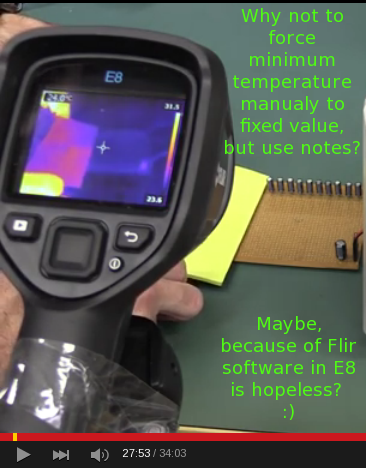
The first thing I've made in custom SeekThermal software was... interface to set manualy temperature min/max ranges and let operator decide to automatic mode or fixed values, etc

When I came across this board in a scrap bin, EEVblog #742 immediately came to mind. It's a bunch of LT1084 regs and a load of Nichicon caps. It probably doesn't set any records, but it would be interesting to see a board with more electrolytics per unit area.
It is marked Cabletron Systems. I suspect it was part of a networking equipment rack, since there was old fiber-optic communication equipment in the bin nearby.
Watching Flir E8 in action, had a lot of fun when notepads had to be used to see anything on its display
The first thing I've made in custom SeekThermal software was... interface to set manualy temperature min/max ranges and let operator decide to automatic mode or fixed values, etc
The Flir has this as standard with no messing about, would have been better if Dave had manually set the span to minimum.
Adding the cheap external lens hack (see E4 thread) make the Ex range incredible for PCB work, I've seen a modified E4 (with lens) side by side with a Flir E60 and Fluke Ti32 and if anything the E4 was better.
Just watched this video. Good stuff! Got a question though that maybe somebody can help me with. When Dave first measured the voltage across the caps with the oscilloscope after applying the 200mA loads he says he's measuring the ripple current (Around 28:20) when obviously he means voltage (he corrects himself later), but then goes on to say that the two circuits have the same ripple current, when what we are actually seeing is that they have the same ripple voltage.
Ripple voltage is ripple current multiplied by total ESR, so couldn't the two circuits have had different ripple currents but the same ripple voltages if the ESR's were also different? For instance the ripple current of the 10 10uF parallel caps could have been half that of the single 100uF cap, but if that circuit had twice the total ESR it would produce the same magnitude of output ripple voltage. I checked the datasheet Dave linked but it doesn't give the ESR's of the caps.
(5 minutes later)
Looking at it again, the ripple voltage Dave displays is a result of I = C*dV/dT capacitive discharge. ESR would have negligible impact at 200mA unless ESR's were up in the ohms range.
But otherwise, surely there's a wide range of performance characteristics for both 470uF and 1000uF capacitors -- there must be 1000uF capacitors out there with a way better ESR than 2x some marginal 470uF capacitors. If the original designer looked at what was available in the catalogue and concluded that 2x 470uF was the way to go back in 1973, isn't it likely that what's in the catalogues has changed since then?
Or, possibly, back then 2 x 470uF was cheaper than one high-spec 1000uF cap.
