-
In this guest video Bob DuHamel from RSD Academy does a follow-up to my opamp tutorial video explaining with a neat visual aid how the virtual ground on an inverting opamp works.
Check out his channel here and subscribe:
https://www.youtube.com/channel/UCOausWDNRDJikQ11gSLj7nA
-
Fantastic, one of the best videos yet! Thanks to Bob and his wonderful assistant.
-
IMO, this has to be featured in any Op-Amp instructional series for beginners.
-
This is the best opamp explanation I’ve ever seen.
-
When I saw this, as soon as I saw him pick up the ruler I just slapped my forehead and instantly knew this was the most obvious visual explanation

He had already posted this video to his channel ages ago and this was against my "rules" for this guest video series, but I couldn't turn down including this one. -
When I saw this, as soon as I saw him pick up the ruler I just slapped my forehead and instantly knew this was the most obvious visual explanation
He had already posted this video to his channel ages ago and this was against my "rules" for this guest video series, but I couldn't turn down including this one.
Thumbs up on "Guest Videos" on you channel Dave.
Although personally I don't know whether your good deed here will have significant impact on your subscriber counts or donations or any advantages for you. But for sure, you've gained a lot of respect and sympathy across Electronics communities around the net.
-
This is the best opamp explanation I’ve ever seen.
I beg to differ. Using the virtual ground method is bound to confuse people. I learned a better method and that is to say the voltage differential between inputs of an ideal opamp is 0V and the opamp sends current through the feedback network to keep it that way. When using the current you can calculate/solve any complex feedback network. -
This is the best opamp explanation I’ve ever seen.
I beg to differ. Using the virtual ground method is bound to confuse people. I learned a better method and that is to say the voltage differential between inputs of an ideal opamp is 0V and the opamp sends current through the feedback network to keep it that way. When using the current you can calculate/solve any complex feedback network.
And I beg to differ with you.
Perhaps the only thing I would add is that the "keeping the inputs the same" process appears to occur magically - it is, at least, not explained. I don't think it would be too much of a stretch to add the two fundamental parameters that round out basic understanding: Propagation delay and open circuit gain.
Specifically - when the input signal changes, there is a moment when the voltage between the two inputs is different. This difference (error) is then amplified and the output is then fed back to the input as a correction. This processing takes time - so during that time, a difference on the input can exist.
HOWEVER, the times involved can be in the nanosecond range - so the window of opportunity is rather short. Add to this the very high gain available and the smallest of errors will get magnified for a very significant impact around the feedback loop.
In short, if we are talking about audio frequency ranges for example, the delay is so small and the gain is so high, that the Op-Amp will, indeed, seem to keep the two inputs the same all the time ... as if by magic.
Get into RF, though, and the magic starts to fade a little. -
That is why I wrote 'ideal opamp'. Ofcourse there is more at play here but to model basic circuits at DC levels I find the method I described much easier and more complete to use. The 'virtual ground' method is just too dumbed down to be useful for circuit design.
-
I think there are two stages to learning a new concept. The first is getting an intuitive feel for the general behaviour of the system, the second stage is learning all the hows and whys and math. You can jump straight to the second stage which is what a lot of schools do. I think you forget your knowledge much faster and are unable to figure it out yourself again.
A really good mental abstraction like the ruler trick in the video can really make a concept stick in your mind and even if you forget the formulas, you can figure them out again.
Of course everyone learns differently. -
Although personally I don't know whether your good deed here will have significant impact on your subscriber counts or donations or any advantages for you.
That wasn't the point. -
The 'virtual ground' method is just too dumbed down to be useful for circuit design.
Rubbish. I've used the "basic rules of opamps" countless times for real circuit design. It creates a nice base model you can either use as-is if your design is not critical, or start to add on other things like offset etc. -
As I wrote before: the 'virtual ground' method is limited and I've seen people shoot themselves in the foot because of it. I certainly felt cheated when I learned the method which uses the current through the feedback network. Why the F*** did they muck about with teaching the 'virtual ground' method while there is a different simple method which always works?The 'virtual ground' method is just too dumbed down to be useful for circuit design.
Rubbish. I've used the "basic rules of opamps" countless times for real circuit design. It creates a nice base model you can either use as-is if your design is not critical, or start to add on other things like offset etc. -
Why the F*** did they muck about with teaching the 'virtual ground' method while there is a different simple method which always works?
Why the F*** you are not teaching different simple method which always works?
-
I remember in my Uni day's being totally confused by 'Virtual Ground'.
I ended up thinking that the inverting node was always at '0V' ... When I actually built my first real world Op Amp circuit the penny finally dropped and I understood that there was a 'Virtual Short Circuit' between the inverting and non-inverting nodes, which made all the text book example make sense.
But that's just me - others understand the virtual ground straight away. It's good to know there are more than one way to describe something. -
That is why I wrote 'ideal opamp'. Ofcourse there is more at play here but to model basic circuits at DC levels I find the method I described much easier and more complete to use. The 'virtual ground' method is just too dumbed down to be useful for circuit design.
Guess its time to make your own much more superior video ? Or at least to proof your idea and point are much better. -
Best guest video so far
-
Is there going to be a list of all the substitute teachers? I'd like to subscribe to all of them for the time being. Dave?
-
As I wrote before: the 'virtual ground' method is limited and I've seen people shoot themselves in the foot because of it. I certainly felt cheated when I learned the method which uses the current through the feedback network. Why the F*** did they muck about with teaching the 'virtual ground' method while there is a different simple method which always works?
And your video or blog teaching this "simple method which always works" is where? -
Why exactly would I need to make a blog or video about it? It is supposed to be common knowlegde for a bachelor level electronics engineer. I already wrote down the gist of it. It doesn't need to be on Youtube to be true.As I wrote before: the 'virtual ground' method is limited and I've seen people shoot themselves in the foot because of it. I certainly felt cheated when I learned the method which uses the current through the feedback network. Why the F*** did they muck about with teaching the 'virtual ground' method while there is a different simple method which always works?
And your video or blog teaching this "simple method which always works" is where?
Say the voltage differential between inputs of an ideal opamp is 0V and the opamp sends current through the feedback network to keep it that way. When using the current you can calculate/solve any complex feedback network. -
Say the voltage differential between inputs of an ideal opamp is 0V and the opamp sends current through the feedback network to keep it that way. When using the current you can calculate/solve any complex feedback network.
FET's are voltage, not current-controlled transistors, right? Now please explain how your "current feedback" network method works for FET input opamp in unity gain mode?
-
The same as it does for any opamp because there is no basic functional difference between FET or BJT opamps (ofcourse there are differences but these have to do with input bias current, input offset voltage, noise, etc). Don't mix 'current feedback' with 'current through the feedback network' because those are totally different topics.Say the voltage differential between inputs of an ideal opamp is 0V and the opamp sends current through the feedback network to keep it that way. When using the current you can calculate/solve any complex feedback network.
FET's are voltage, not current-controlled transistors, right? Now please explain how your "current feedback" network method works for FET input opamp in unity gain mode? -
The same as it does for any opamp because there is no basic functional difference between FET or BJT opamps (ofcourse there are differences but these have to do with input bias current, input offset voltage, noise, etc). Don't mix 'current feedback' with 'current through the feedback network' because those are totally different topics.Say the voltage differential between inputs of an ideal opamp is 0V and the opamp sends current through the feedback network to keep it that way. When using the current you can calculate/solve any complex feedback network.
FET's are voltage, not current-controlled transistors, right? Now please explain how your "current feedback" network method works for FET input opamp in unity gain mode?
You did not answer my question. I do not see any explanation or calculation/solution. Please *show* how your method works by example.
-
Take this circuit for example. Using the 'virtual ground method' you can quickly see that Vo/Vi= Rf/R1 *-1 = -10.
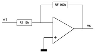
The method I learned during my studies is as follows: the current into the ideal opamp inputs is zero and the voltage differential between the inputs is zero. For this circuit this means that IRf=-IR1 and V-=0V. When applying 1V to V1 this means that the current through R1=1/10k=100uA. Since IRf=IR1 -> IRf=-100uA -> VRf=100k * -100uA= -10V = Vo. Vo/Vi=-10
Now lets make things more challenging: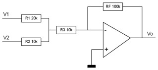
Using the virtual gound method isn't so straightforward anymore!
But we can set some equations: First of all: IRf=-IR3, V-=0V, IR3=IR1+IR2
When applying one Volt to V1 and zero Volt to V2 the current through R1 becomes 1 / (20k + 10k//10k) = 1/25k = 40uA. The current through R3 is half of that: 20uA (one leg of 10k parallel with 10k). This means IRf=-20uA -> Vo=-20uA * 100k = -2V -> Vo/V1=-2
When applying one Volt to V2 and zero Volt to V1 the current through R2 becomes 1 / (10k + 20k//10k) = 1/16.7k = 60uA. The current through R3 is 2/3 of that: 40uA (10k leg of 10k parallel with 20k). This means IRf=-40uA -> Vo=-40uA * 100k = -4V -> Vo/V2=-4
I'm not pulling this example out of my ass. Someone had designed a similar circuit using the 'virtual ground' method and came up with amplifications which where 'close' but not what he was expecting. That was probably caused by using -Rf/ (R2+ R1// R3) for Vo/V2 or something similar due to wrongly assuming the - input of the opamp to be a ground. -
Watching this