-
[RESOLVED!!!] Arduino UNO COLOUR NTSC Output with AD725 - Bad colours issue...
Posted by Axxel on 23 Sep, 2019 17:18 -
Dear friends.
I repost here what I posted on the Arduino forum...
https://forum.arduino.cc/index.php?topic=637290.0
Why I do that? Because this problem I have dosen't looks to be a pure Arduino problem but an electronics problem with the RGB->COMPOSITE video converter AD725...
So... Here we go!
I'm trying to make an NTSC color pattern generator based on Arduino UNO full stock with stock 16mhz oscilator.
The TVout Library looks great and works with interrupts, but the problem I tried to understant it, there is a lot of assembler code, and I don't understand nothing at the assembler code... It is very difficult for me to mod the library to get a colour output... due to my lack of assembler language...
So I made a RGB + Sincro generator with a "raw method" and more easy to understand code based on this thread:
https://forum.arduino.cc/index.php?topic=43085.0
I modded it a little bit to have R, G and B channels.
With some modifications to have an RGB output here is the code:
You can download the code in the attachment.
If you want this code run, please upload and compile with Arduino IDE 1.0.6. With the more recents one like 1.8, it will not work, another problem I have to FIX later... This should be due to the NOP; asm instruction... I don't know...
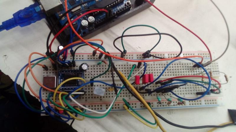
I use this diagram to connect the AD725:
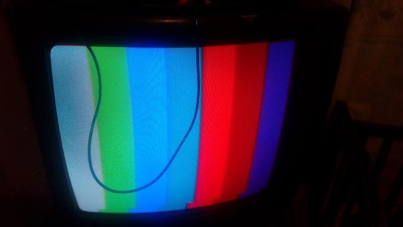
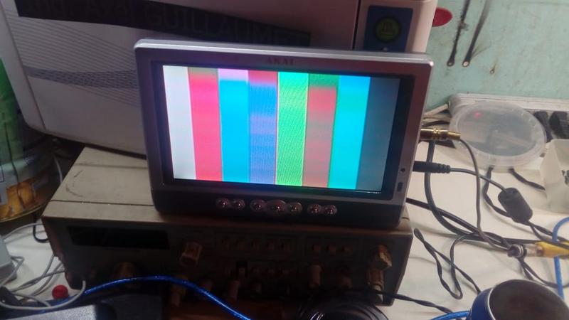
The problem are the colours.
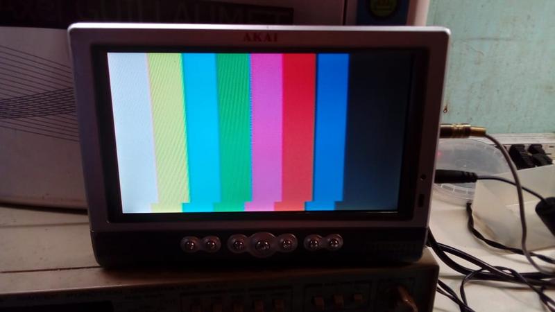
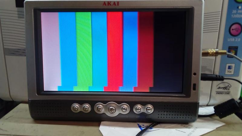
Instead of THIS,
I have this:
The problem is not with pure R pur G or pure B, the problem is when I mix for example blue and red, as you can see instead of pink, I have a full-red...
The red looks pale red.
The yellow looks pale green.
The green doesn't look... green but light blue...
The white is not white but like gray...
I loaded the game toorum quest 2.
http://petenpaja.blogspot.com/2013/11/toorums-quest-ii-retro-video-game.html
I have the same problems...
So I think this is an issue with the AD725 RGB to PAL/NTSC encoder... I tried to change the resistors from the arduino to the AD725... No results.
I think this issue is with the PIN 12 YTRAP... But I'm not sure...
If someone had experience with the AD725 chip it can be great for hepling me there!
Best regards...
UPDATE AND SOLUTION
Here was the problem, the cable to the 4OSC pin when I move it, the colours changes.
I shorted this cable as much as posible and here we go!
-
Looking at your schematic, you've selected PAL instead of NTSC.
-
Hi! This is an error of my schematic. On my protoboard, this pin go to +5V pin. I actualized the schematic.
But the problem isn't here.
-
I think this issue is with the PIN 12 YTRAP... But I'm not sure..
I don't think it will be the YTRAP because there shouldn't be much 3.5MHz in the colour bar's luma anyway. I'd give it a try just leaving pin 12 open. All the long leads around the AD725 won't help much.
-
I think this issue is with the PIN 12 YTRAP... But I'm not sure..
I don't think it will be the YTRAP because there shouldn't be much 3.5MHz in the colour bar's luma anyway. I'd give it a try just leaving pin 12 open. All the long leads around the AD725 won't help much.
I removed the inductance and the ceramic capacitor... It doesn't change anything. Same problem. -
I removed the inductance and the ceramic capacitor... It doesn't change anything. Same problem.
I suppose that's right, with no 3.5MHz luminance in the colour bars it shouldn't have made any difference anyway.
I can't think of any combination of fault that would change the colour bars to the colours you're getting.
http://kudelsko.free.fr/mires/fonctionnement2.htm -
I connected the system on my bedroom tv (CRT). Exactly the same problem... So I can discard the LCD test monitor...
-
I suppose you could try one colour at a time, just disconnecting and grounding the other inputs, the link I posted shows what the separate shapes of the RGB signals should be.
-
Your MCU should be powerful enough to do NTSC output directly; this is PAL, but a similar idea:
http://www.linusakesson.net/scene/phasor/ -
Your MCU should be powerful enough to do NTSC output directly; this is PAL, but a similar idea:
http://www.linusakesson.net/scene/phasor/
Dear friend. The idea of this project is to make an analog video synthesizer. I will use the arduino only to generate the VSync and the HSync into R G and B signals. The R, G and B signals will me maked by oscilators with various LFOs etc........I suppose you could try one colour at a time, just disconnecting and grounding the other inputs, the link I posted shows what the separate shapes of the RGB signals should be.
Here there is a video:
https://youtu.be/mrLbUIjj_SA
As you can see, the GREEN isn't green but looks like a pale blue.
The red isn't red but look like a maroon
And the blue looks like dark pruple...
As I can see RGB signals are from 0V to 1V... If by error I put +5V at the RGB inputs of the AD725 is there a risk of damage of the AD725? -
Sorry, but trying to do this on a breadboard is simply utopic. Try a stripboard with short interconnects.
-
Not sure if anyone has already suggested it, but everyone seems to be stuck on the hardware side of things...
Are you certain this is not a software issue there? The colors are one thing, but the shifted lines towards the bottom of the screen suggest there is likely a software issue.
-
Why are you using:
#01ff00 instead of #00ff00?
#fb0102 instead of #ff0000?
#0301ff instead of #0000ff?
I agree it shouldn't make much difference in result, but if you're going to call them pure colors use the pure input values. And if those colors suddenly work better, you will have discovered a mixing problem!
-
I have to repeat myself:
Sorry, but trying to do this on a breadboard is simply utopic. Try a stripboard with short interconnects.
Got it?
-
Why are you using:
#01ff00 instead of #00ff00?
#fb0102 instead of #ff0000?
#0301ff instead of #0000ff?
I agree it shouldn't make much difference in result, but if you're going to call them pure colors use the pure input values. And if those colors suddenly work better, you will have discovered a mixing problem!
Dear freind, those HEX value don't mean nothing in this case, this picture is only here to illustrate (I removed then and rectified my initial post) and as you can see I send only R,G and B values 0 or 1 - So we must obtain only 8 colours with this, not all the grayscales of each channel.
I have to repeat myself:Sorry, but trying to do this on a breadboard is simply utopic. Try a stripboard with short interconnects.
Got it?
Dear frind. I can make a design with Eagle and make a PCB this is not a problem for me, but before I will wait to have some more corrects results. I agree with you, those wires can create some perturbations like noise on the picture but an error of this grade I don't think so.Not sure if anyone has already suggested it, but everyone seems to be stuck on the hardware side of things...
Are you certain this is not a software issue there? The colors are one thing, but the shifted lines towards the bottom of the screen suggest there is likely a software issue.
Dear friend. This is a very interesting point, and here I will explain what I do:
I have a NTSC pattern generator with PIC which is working well. The converter that use is the MC1377, a very good chip but OBSOLETE and DISONTINUED Yes, I can find it on Aliexpress but I think this is a chinese clone and developing something with an obsolete base is not a good idea. The AD725 looks more recent and it is disponible on newark.
So, as you can see, I identified on the PIC the sync R G B outputs and I connected the arduino instead of the PIC to use all the MC1377 circuitery and surpise! It works! Correct colours here!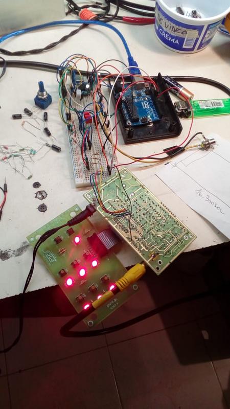
Now, let's make the same operation but reverted... Let's send the PIC outputs SYNC R G and B signals to the AD725 breadboard. Same problem, bad colours...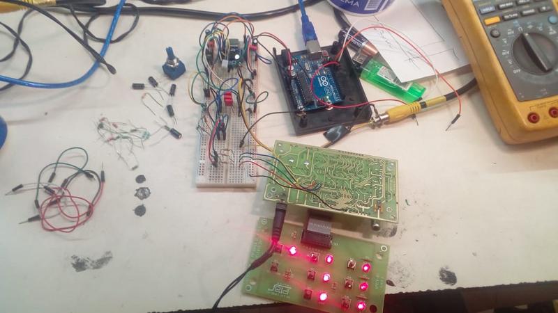
So I can conclude : THIS IS NOT A FIRMWARE ISSUE but a AD725 circuit problem...
Is my AD725 has the inputs burned?
-
Simple enough to check, just try another AD725...
-
Dear friends.
I repost here what I posted on the Arduino forum...
https://forum.arduino.cc/index.php?topic=637290.0
Why I do that? Because this problem I have dosen't looks to be a pure Arduino problem but an electronics problem with the RGB->COMPOSITE video converter AD725...
So... Here we go!
I'm trying to make an NTSC color pattern generator based on Arduino UNO full stock with stock 16mhz oscilator.
The TVout Library looks great and works with interrupts, but the problem I tried to understant it, there is a lot of assembler code, and I don't understand nothing at the assembler code... It is very difficult for me to mod the library to get a colour output... due to my lack of assembler language...
So I made a RGB + Sincro generator with a "raw method" and more easy to understand code based on this thread:
https://forum.arduino.cc/index.php?topic=43085.0
I modded it a little bit to have R, G and B channels.
With some modifications to have an RGB output here is the code:
You can download the code in the attachment.
If you want this code run, please upload and compile with Arduino IDE 1.0.6. With the more recents one like 1.8, it will not work, another problem I have to FIX later... This should be due to the NOP; asm instruction... I don't know...
I use this diagram to connect the AD725:
The problem are the colours.
Instead of THIS,
I have this:
The problem is not with pure R pur G or pure B, the problem is when I mix for example blue and red, as you can see instead of pink, I have a full-red...
The red looks pale red.
The yellow looks pale green.
The green doesn't look... green but light blue...
The white is not white but like gray...
I loaded the game toorum quest 2.
http://petenpaja.blogspot.com/2013/11/toorums-quest-ii-retro-video-game.html
I have the same problems...
So I think this is an issue with the AD725 RGB to PAL/NTSC encoder... I tried to change the resistors from the arduino to the AD725... No results.
I think this issue is with the PIN 12 YTRAP... But I'm not sure...
If someone had experience with the AD725 chip it can be great for hepling me there!
Best regards...
I used to play with PAL picture monitors for a living, & I have definitely seen an incorrect display like yours.
It could be due to phase and/or level errors in the encoding, differential phase errors in the amplifier stages after the encoder, or faulty decoder or colour difference amplifiers in the monitor.
The fact that the fault is the same with another TV seems to rule the last cause out, though.
Differential Phase in NTSC systems can definitely cause colour errors---- with PAL, it is effectively,cancelled out, but still has the effect of desaturation of colours.
An allied effect is Differential Gain, which causes the same sort of desaturation with luma level.
These are both linearity based problems which affect Composite video.
As the chroma "rides" upon the luma waveform, if the amplifier is non linear, the chroma will tend to be "crushed" or "stretched" depending upon the luma level.
This normally results (in NTSC) in colours being changed both in hue & saturation, but your result looks like the total loss of one colour difference signal.
What would make things easy would be if you had a vectorscope!
I have a vague memory of switching a video generator so that the phase was NTSC, but the subcarrier was PAL, & that caused a similar dsplay to yours, but the last time I played with this stuff was in 1999!
I don't know if this "stream of consciousness" type rambling is much help, but I can't offer much more at the moment!
-
Your earlier first photographs look like a massive overshoot of the source RGB levels into the video encoder, or, a chroma colorburst phase error. Try cutting the source RGB luminence by 50%.
If that doesn't work:
Your latest photo with the 2 colors above and below the screen show a problem with the chroma colorburst maintaining lock hue due to a source video impure/un-exact source video sync, sometimes due to the inaccuracies generated by microcontroller software video pattern generators. The only way to fix this is to fix the software, or, use really old all analog IC color encoders and only old analog TVs to display these images as new modern TVs with digital color decoders expect a constant relationship between video sync and the 3.579545Mhz color burst signal unless they go into low quality VCR color decoder mode. To trick these IC into this mode, you would need to sloppily replicate the video output timing errors of a VCR's video head speed & video tape timing alignment.
However, this still means a proper 525i or 263p reference source lines. Also, the COMPOSITE sync you are sending out requires all the proper stabilization pulses as they encoder may use these to know when to stop placing color bursts when the vertical sync is about to begin.
-
Vectorscope... Ahhhh.. Vectorscope... I saw one 3 or 4 years ago in a junk market... I saw it, it was cheap (40 euros) but I didn't bought it because I didn't think one day I will need it and I didn't know if it was working... And fixing it... I seriously doubt if I have the skills and the material to fix it
But...
Yes, I tried various values of divisors bridge(1K with 4.7K - 1K with 5.6K, i quited the 75ohms resistors to try with 220,330,1K) the only thing I get is unpowering the intensity of the colour of the channel. BUT the CHROMA doesn't get fixed, the same colours but darker...
Here is why there is a probability there:However, this still means a proper 525i or 263p reference source lines. Also, the COMPOSITE sync you are sending out requires all the proper stabilization pulses as they encoder may use these to know when to stop placing color bursts when the vertical sync is about to begin.
The wierdest thing there is the arduino RGB code encodes perfecfly with the MC1377, as you can see in these pictures.
And as I remind... At the begining in the firsts firsts tests, I was getting the correct colours... But I'm not sure...
Probably the AD725 is damaged... I don't know...
The problem now I havn´t any AD725 here...
I bought 5 AD725 on Aliexpress, I will receive them next month
And I bought an AD724 on Newark, hope this one will come soon there! -
Random thoughts...
For the RGB inputs the AD725 data sheet says 0mV to 714mV AC-Coupled, and the 470R->75R dividers should give about 680mVpp, so close enough. I think more than enough has been tried to eliminate the RGB input levels. From the data sheet I don't think 0 to 5V DC would harm the RGB inputs, but I don't think there's any point either.
The RGB inputs clamp the AC coupled side to 0mV themselves. Is the HSYSNC connected? Just in case.
I don't agree that this can't be made to work on a breadboard even on a carrier, because the 3.5MHz colour and it's critical phase are all done inside the AD725 from the 14MHz clock, By the time the 3.5MHz appears in the composite video output it's critical timing has already been done, - in theory.
The video output wire's GND should be very close to the AD725's GND, even if it is just 2 bits wire. If the video output ground is just connected to a breadboard ground somewhere the phase of the 3.5MHz colour could well be off a bit, due to the breadboard GND noise and inductance.
Is there any power decoupling on the AD725's carrier? 100n would do.
Around the AD725 and carrier I'd definitely be using short lengths of single core instead of the long breadboard wires.
A scope would be useful.
-
How about a normal scope shot of the NTSC output waveform.
Also, what happens when you adjust the 'TINT' control on your monitor?
-
How about a normal scope shot of the NTSC output waveform.
Also, what happens when you adjust the 'TINT' control on your monitor?
My osciloscope fails, I will buy a rigol in a near future... I have an old one, I tried to get the NTSC signal but........ hard to see clearly...
Of course I tried to adjust the TINT parameter of the monitor, but I can't find the correct colours....Random thoughts...
For the RGB inputs the AD725 data sheet says 0mV to 714mV AC-Coupled, and the 470R->75R dividers should give about 680mVpp, so close enough. I think more than enough has been tried to eliminate the RGB input levels. From the data sheet I don't think 0 to 5V DC would harm the RGB inputs, but I don't think there's any point either.
The RGB inputs clamp the AC coupled side to 0mV themselves. Is the HSYSNC connected? Just in case.
I don't agree that this can't be made to work on a breadboard even on a carrier, because the 3.5MHz colour and it's critical phase are all done inside the AD725 from the 14MHz clock, By the time the 3.5MHz appears in the composite video output it's critical timing has already been done, - in theory.
The video output wire's GND should be very close to the AD725's GND, even if it is just 2 bits wire. If the video output ground is just connected to a breadboard ground somewhere the phase of the 3.5MHz colour could well be off a bit, due to the breadboard GND noise and inductance.
Is there any power decoupling on the AD725's carrier? 100n would do.
Around the AD725 and carrier I'd definitely be using short lengths of single core instead of the long breadboard wires.
A scope would be useful.
Yes, the divisor brigde is correct. The HSYNC go to the +5V. There are 100nf and 22uf decouplers on the analog power line and the digital power line. Scope... not posible for the moment...
But yes! I'm waiting for the AD724 soon, I bought it yesterday!
-
"The HSYNC go to the +5V."
Do you mean VSYNC, if HSYNC is not being driven that might be the colour problem.
"The AD725 accepts two common sync standards, composite sync or separate horizontal and vertical syncs. To use an external composite sync, a logic high signal is input to the VSYNC pin and the composite sync is input to the HSYNC pin. If separate horizontal and vertical syncs are available, the horizontal sync can be input to the HSYNC pin and vertical sync to the VSYNC pin. Internally, the device XNORs the two sync inputs to combine them into one negative-going composite sync.
The AD725 detects the falling sync pulse edges, and times their width. A sync pulse of standard horizontal width will cause the insertion of a colorburst vector into the chroma modulators at the proper time. A sync pulse outside the detection range will cause suppression of the color burst, and the device will enter its vertical blanking mode. During this mode, the on-chip RC time constants are verified using the input frequency reference, and the filter cutoff frequencies are retuned as needed." -
Dear friends!
I'm back there with some BAD news...
I received the AD724. With this chip there is not colour trap, there is only an OSC - 4OSC Selector, so PIN12 to +5V.
And I have ABSOLUTELY the same ugly colours...
Here is the NTSC output seen on the osciloscope... My oscilsocope is OLD, and really tired... Bastetime is at 10usec/div, 0.2V/div and the 0 on the center.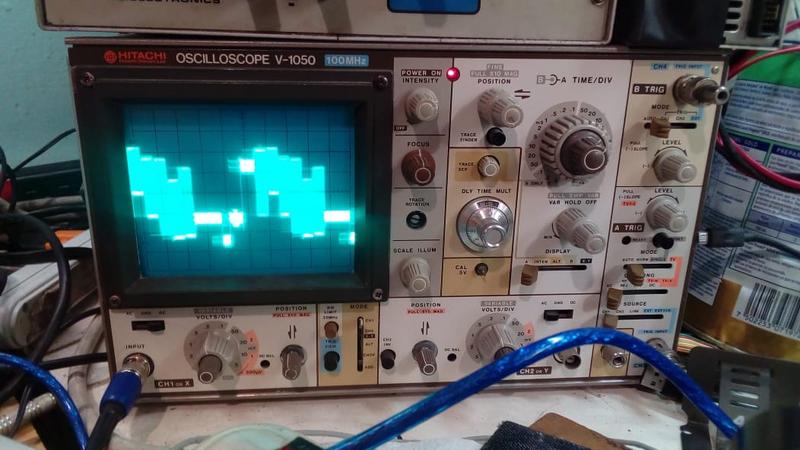
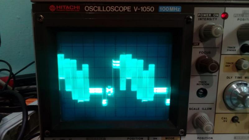
Sure, the problem is not the Analog Devices chip...
Software should be the answer? -
On page 10 of the datasheet, you can find an interesting test circuit which uses a VGA port. You can try the chip using the same test signal you want to generate with the Arduino, and seek for the differences between the VGA Signal and the RGB you are trying to emulate.