-
Hi.
I have a thermocouple connected to an amplifier using a differential circuit with a 250x gain. The circuit works well and provides accurate consistent results however I get some spikes into my microcontroller which can throw off my control algorithms. Whilst i could potentially perform a higher rate of sampling and average the results in my micro i would rather do this at a hardware level to take some load of the controller. Is it possible to place a low value capacitor in a bypass configuration on the output of my amplifier setup reducing some of the output ripple? or would this cause my output to skew too much?
Any help would be appreciated as analogue electronics are still new territory for me, TTL always feels much easier
-
You have been somewhat sparse with the details of the noise character, is it like shot noise?, one shot extreme transients spikes? If so then you do not want to average them in you want to exclude those samples in software somewhat like key press debouncing. Most temperature measurement happens in physical systems with a lot of thermal inertia, things just don't change that fast compared to micro cycle times and A to D sample rates. Excluding fast transients is very low computational overhead.
-
I have seen a few high transient spikes although rare and i have been excluding them by ensuring temperature readings do not deviate by more than ten degrees. The temperatures do change somewhat quickly, about 2 degrees a second is expected. It just surprises me that on logged outputs i can have fluctuations of 1-2 degrees between each reading about 20ms apart. So my thought had been to use a capacitor to smooth out the temperature gradients. Either that or im worried about nothing.
-
Most thermocouples are heavily low pass filtered, as generally they are not a fast response. A 1 sec RC filter is common, using 1M and a 1uF good quality ( not ceramic, electrolytic or tantalum) polyester or polycarbonate film capacitor between the amplifier and the ADC input. Most of the spikes are noise coupled into the thermocouple leads.
Great, thanks for the advice.
I have looked a little more into some of the recomended filters and i may put in and RF filter before the amplifier as well. -
Maybe you could try LMP90100 from Natio... erhm, TI. They are designed to work well with thermocouples and they have some really nice tips in datasheet regarding interfacing various temperature sensing elements. The thermocouple one I have used almost unmodified as it was in datasheet and it worked like a charm.
And filtering you can do in software. -
Not a bad device but i needed something that was through hole and it is rather hard to find something in a DIP format outside of Op-Amps still a good solution for further projects though.
-
Quite often i will do a running average coupled with code to ignore the lowest and highest values obtained within the period.
It works quite well to remove glitches, -
Even with filtering thermocouples produce quite jittery outputs. So even after hardware filters have been applied I would suggest oversampling and averaging, for example taking ten successive measurements and dividing by ten.
-
I think that the most accurate and precise methos of temperature measurement are various temperature dependant resistive elements (i.e. PT100, PT1000). of course these can run from few cents to some hundreds of dollars. AFAIR from the LMP datasheet, the application of those takes a little more effort into input compensation, but they are more accurate than thermocouples (especially the most popular k-type)
-
Thermocouples go nicely from liquid Helium to molten iron using the same sensor. Pt100 does -100C to 150C reliably, outside that it tends to fail with time. I use Pt100 clones ( much cheaper than the actual platinum wire ones, these are platinum film on ceramic) to do temp sensing, and just keep a spare sensor or three around, as they fail every 2 years or so.
TC are poor near room temp, but then you have better sensors for that range, in silicon and resistive, and the silicon ones are available with 1 wire output and an alarm. -
Yes i am finding all about these fun fluctuations, i like the the idea of min/max rejection though as well as the over sampling. I may incorporate that as i try to move the code away from the floating point math at the same time.
I would prefer an RTD although the cost is a bit higher and many of them appear to have narrower temperature ranges as i at least need the probe to handle up to 300 degrees C. The TMP36 I have for cold junction compensation is much more stable. -
Hi, if you're using the microcontroller's internal ADC, you will need to perform some sort of software filtering, AND you'll need the RC at the ADC's inputs. This is because the ADC acquisition noise can be pretty terrible and can make the count vary transiently by several LSB depending on a variety of conditions, even with a perfectly smooth input. The biggest input cap in the world won't prevent this noise which comes from all the digital stuff on the die.
The input RC is necessary to prevent aliasing. And/or put a hefty cap in the feedback loop of your op-amp to reduce its HF gain. Make sure impedance looking out of the ADC pin on the micro is less than 10K. In other words, don't use 1M+1uF, directly at the pin, buffer it with a unity gain buffer. Better still, sample the input every 1ms and use 10K+1uF direct at the pin.
Adding a very simple first order software IIR filter is very easy and use hardly any processor resources assuming you're sampling at regular time intervals anyway. Here it is:
http://electronics.stackexchange.com/questions/30370/fast-and-memory-efficient-moving-average-calculation. Make sure you use signed arithmetic!
I can't recommend implementing this enough. Here's some untested C:Code: [Select]//call this function very regularly
//uses signed integers because of intermediate negative values in calculation
signed int read_analogue_iir(unsigned char ad_channel) {
//result = oldresult + (( newresult - oldresult) / hardness )
//where hardness is the settling time
//info here: http://electronics.stackexchange.com/questions/30370/fast-and-memory-efficient-moving-average-calculation
#define IIR_HARDNESS 64 //bigger numbers increase smoothing. Use power of 2 numbers.
static signed int prev_val; //for illustration only, use array with 'ad_channel' as index, otherwise you'll need a variable for each channel.
signed int temp;
temp = (signed int)(sample_adc(ad_channel)); // calls function to get ADC sample from 'ad_channel'.
prev_val = prev_val + ( (temp - prev_val) / IIR_HARDNESS ); //everything MUST be signed, NOT unsigned.
return prev_val;
}
-
@lewis: Wow, lots of good discussion on that stackexchange question!
I've been playing around with biquadratic filters for this kind of thing. The theory looks a little arcane, but the implementation isn't so bad:Code: [Select]int operator()(int sample) {
int result = a0*sample + a1*x1 + a2*x2 - a3*y1 - a4*y2;
x2 = x1;
x1 = sample;
y2 = y1;
y1 = result;
return result;
}
The cool thing is that this one function can do several different kinds of filters just by changing the coefficients. Here's some more discussion. -
That code makes a lot of sense, ensuring small changes between readings and preserving memory space for averaging. However i must admit the biquadratic filters are still a litt confusing to me, i never managed to get my head around understanding the frequency domain. The thing i am not sure about is what a hefty capacitor would be in this situation? I have modified my schematic to include the new filtering and i think it will certainly improve my results. I also ensured that i have a bypass capacitor right next to the supply & reference of my ADC so as to remove some of the noise from there.
-
I've recently finished a kiln controller that uses a K-type and the ad595; I had problems with the readings; so the code I used took X number of samples at Y milliseconds apart, and if the readings are within a preset tolerance it returns the value otherwise it re-samples; It seemed to do the job fine. Also I added a couple of lines of code to toggle a piezo sounder every time it takes a sample; When I ran it in my hobby lab upstairs (lots of gear on, close to computers etc) I could hear it taking a few samples before the ADC values settled. When I ran it actually on the kiln it ran better pretty much all the time except for when the combi-boiler fired-up (ignited) and it would have to take more readings because I could hear it.
https://www.eevblog.com/forum/projects-designs-and-technical-stuff/kiln-controller-project/msg146286/#msg146286
not sure if that info helps! ;-) -
That looks really interesting jucole. I am working on something very similar that I am going to write up very soon. I think an margin checking, coupled with lewis's averaging should give a much nicer, cleaner signals. I also come across antoher interesting schematic for thermocouples utilising a LTC2053 instrumentation amplifier, unfortunatly only available in a surface mount package so not useful for my application however the datasheet provides some useful notes on filtering out noise in the feedback loop. http://cds.linear.com/docs/Design%20Note/dn302f.pdf
-
That code makes a lot of sense, ensuring small changes between readings and preserving memory space for averaging. However i must admit the biquadratic filters are still a litt confusing to me, i never managed to get my head around understanding the frequency domain. The thing i am not sure about is what a hefty capacitor would be in this situation? I have modified my schematic to include the new filtering and i think it will certainly improve my results. I also ensured that i have a bypass capacitor right next to the supply & reference of my ADC so as to remove some of the noise from there.
You need to put the feedback cap in parallel with the feedback resistor - so R6 goes between the op-amp output and the inverting input and C7 goes in parallel with R6. You'll also need another cap across R8, the same value as the cap across R6.
'Hefty' means about 100nF - that's a good starting point. Use polyester film or polypropylene. You might need 47nF or 220nF, or something like that. (Normally capacitors around op-amp feedback loops are in the order 10pF or so, so 100nF is pretty 'hefty' by those standards).
If you find the op-amp oscillates with the feedback caps (it shouldn't do, but might) then put a 47R series resistor right at the op-amp's output.
That LT app note looks very useful, it's worth thinking about cold junction compensation if you need absolute accuracy - that's what the LTC1025 is doing in the diagram on page 2.
You should be ok with this belt and braces approach - the op-amp feedback caps help prevent the op-amp amplifying noise and RFI from the thermocouple, the RC filter attenuates noise even more to help prevent aliasing at the ADC, and the IIR filter gets rid of acquisition noise. You can even tweak the gain of the diff-amp to give you more output voltage so you use more of the ADC's range, as long as the maximum temperature you expect results in a voltage slightly less than the ADC reference voltage. This improves signal-to-noise ratio as well as measurement resolution and helps even more. That's the belt-and-braces-with-cable-tie-and-gaffer-tape approach.#
@andy - that biquad filter looks good, never made a digital implementation but have used their analogue counterparts a few times in audio applications. Looks like you need a micro with an FPU to use it, assuming those coefficients are doubles and not ints. -
@andy - that biquad filter looks good, never made a digital implementation but have used their analogue counterparts a few times in audio applications. Looks like you need a micro with an FPU to use it, assuming those coefficients are doubles and not ints.
The biquad seems to work pretty well with fixed point at run time. At "compile" time, you'll need floating point to calculate the coefficients. I'm using 32-bit values in B16 to represent the filter state. That just multiplies the fractional coefficients you'd normally use by 2^15. Each term of the polynomial has the same scaling applied, so at run time it can be evaluated in B16 with the result converted back to "normal" with a single division:Code: [Select]result = (a0*sample + a1*x1 + a2*x2 - a3*y1 - a4*y2)/scale;
My sample values are only 12-bits, so I think it's reasonably safe from overflow. If it did overflow (depending on coefficients), I'd look at re-ordering the polynomial terms to squeeze out a little more before messing with precision. -
I am working on something very similar that I am going to write up very soon.
Cool, I'd be interested to read that!
I took the easy option with the ad595 as it has 10mV per 1'c and cold point compensation; I used a Haven Thermo-Calibrator to simulate temperatures.
When I first used the Thermo-Cal it actually messed up my readings but I wasn't sure why; So I hooked it up to my el-cheapo old scope and found some spikes on the line, I tried averaging but If I fell on any spikes it just messed it up. So I opted to take multiple samples and discard any values that weren't within the set tolerance.
The upper channel in the pic shows the spikes; the lower channel shows little blips, the blips are my uC sampling periods output on channel 2 via a gpio pin; So only when the blips miss any spikes the value is returned. I'm not sure if this the proper way to do it as I don't do electronics and I'm crap at math but it does work for me!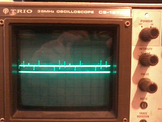
-
The biquad seems to work pretty well with fixed point at run time. At "compile" time, you'll need floating point to calculate the coefficients. I'm using 32-bit values in B16 to represent the filter state. That just multiplies the fractional coefficients you'd normally use by 2^15. Each term of the polynomial has the same scaling applied, so at run time it can be evaluated in B16 with the result converted back to "normal" with a single division:
Code: [Select]result = (a0*sample + a1*x1 + a2*x2 - a3*y1 - a4*y2)/scale;
My sample values are only 12-bits, so I think it's reasonably safe from overflow. If it did overflow (depending on coefficients), I'd look at re-ordering the polynomial terms to squeeze out a little more before messing with precision.
Aha, of course. I use something similar for fast rms calculation to get accurate results without square rooting a double. My code does require a hardware multiplier, but it does just about run on a pic16 if you're feeling brave. -
I'm not sure if this the proper way to do it as I don't do electronics and I'm crap at math but it does work for me!
That board in your other post is pretty damn good for someone that doesn't do electronics! -
That LT app note looks very useful, it's worth thinking about cold junction compensation if you need absolute accuracy - that's what the LTC1025 is doing in the diagram on page 2.
I've has some bad experience with LTC1025 - the readings were smooth at low temperatures, but started behaving wildly at higer temps. And it was only noisy while connected to a thermocouple in kiln, I couldn't simulate this with external voltage. But when I removed cold junction compensation of LTC1025 - the noise just went away. I'm attaching two plots to ilustrate that.
-
I've has some bad experience with LTC1025 - the readings were smooth at low temperatures, but started behaving wildly at higer temps. And it was only noisy while connected to a thermocouple in kiln, I couldn't simulate this with external voltage. But when I removed cold junction compensation of LTC1025 - the noise just went away. I'm attaching two plots to ilustrate that.
Thanks for the heads up. Seems strange, I've always had good experience with Linear parts, but will keep a lookout if I ever need to use this one! -
You need to put the feedback cap in parallel with the feedback resistor - so R6 goes between the op-amp output and the inverting input and C7 goes in parallel with R6. You'll also need another cap across R8, the same value as the cap across R6.
'Hefty' means about 100nF - that's a good starting point. Use polyester film or polypropylene. You might need 47nF or 220nF, or something like that. (Normally capacitors around op-amp feedback loops are in the order 10pF or so, so 100nF is pretty 'hefty' by those standards).
If you find the op-amp oscillates with the feedback caps (it shouldn't do, but might) then put a 47R series resistor right at the op-amp's output.
I will breadboard this today and demonstrate the difference, thanks for the advice. I had picked out the capacitor placement was wrong but completely missed the second cap. I assume this is to balance the amplifier? Infact better still i think i will go back to pen and paper and run the long forgotten equations (i know that textbook is here somewhere) just so i have a clean understanding of the circuit.That LT app note looks very useful, it's worth thinking about cold junction compensation if you need absolute accuracy - that's what the LTC1025 is doing in the diagram on page 2.
Yeah i took the easy way out here and just ran a TMP36 into another ADC channel and did the compensation in software. Should also help me keep an eye on board temperature as well.You should be ok with this belt and braces approach - the op-amp feedback caps help prevent the op-amp amplifying noise and RFI from the thermocouple, the RC filter attenuates noise even more to help prevent aliasing at the ADC, and the IIR filter gets rid of acquisition noise. You can even tweak the gain of the diff-amp to give you more output voltage so you use more of the ADC's range, as long as the maximum temperature you expect results in a voltage slightly less than the ADC reference voltage. This improves signal-to-noise ratio as well as measurement resolution and helps even more. That's the belt-and-braces-with-cable-tie-and-gaffer-tape approach.#
I think it is fare to say i have a lot to learn to improve this design and clear it up although i feel it is precise enough for my current application. How long have you been building analogue circuits lewis? Are there any texts or projects you would recomend?
Cool, I'd be interested to read that!
I took the easy option with the ad595 as it has 10mV per 1'c and cold point compensation; I used a Haven Thermo-Calibrator to simulate temperatures.
When I first used the Thermo-Cal it actually messed up my readings but I wasn't sure why; So I hooked it up to my el-cheapo old scope and found some spikes on the line, I tried averaging but If I fell on any spikes it just messed it up. So I opted to take multiple samples and discard any values that weren't within the set tolerance.
The upper channel in the pic shows the spikes; the lower channel shows little blips, the blips are my uC sampling periods output on channel 2 via a gpio pin; So only when the blips miss any spikes the value is returned. I'm not sure if this the proper way to do it as I don't do electronics and I'm crap at math but it does work for me!
I like the look of that thermo-cal unit although im always a sucker for new tools. I considered using the ad595 but they are really expensive for my liking although they do provide a no-nonsense signal. Damn if you dont do electronics or maths, what hope is there for the rest of us when you do!
well im off to jaycar...