-
Vacuum fluorescent display rejuvenation...SUCCESS
Posted by
willb
on 04 Aug, 2013 00:12
-
So I just bought a Fluke 6060A synthesized RF generator from eBay, broken. It was sold with as "fan spins, nothing on display/bad display". All it needed was a filter cap for the +37VDC rail, and a pin re-seated on a connector for the +6.2VDC bias for the VFD. Now that I have it up and running, I have another issue...
Both VFD's are very dim. This unit seems to have a lot of hours on it. The displays are legible, but dim. I have pretty much given up on finding replacement displays for my unit. The voltages seem mostly to be within spec (6vac for the filament, DC bias is a little low at 6.05v). Would a slightly low bias dim the display considerably?
Would it be possible to rejuvenate a VFD in the same way as you would with a CRT by slightly increasing the filament voltage for a few seconds? Anyone have any experience with bringing back old VFD's?
Thanks!
-
#1 Reply
Posted by
xrunner
on 04 Aug, 2013 00:43
-
Both VFD's are very dim. This unit seems to have a lot of hours on it. The displays are legible, but dim.
I was given an older stereo by a neighbor, because they were going to throw it out. I was going to use it to power a set of outdoor speakers ... anyway it hadn't been used for many years and the display, which is the same type as you are having trouble with, was very, very dim. I left it on for several days and it just got better on it's own.

-
#2 Reply
Posted by
SeanB
on 04 Aug, 2013 06:48
-
Boosting filament voltage will not help, it is a case of the phosphor on the anodes having degraded with constant power. You could increase the anode voltage a little, to the upper end of the anode supply range, but this may kill the driver chip. Try cleaning the inside of the display filter in the case, often there is a fine dust film there, which dims the display.
-
-
Yes, and I've done it many times with good results. The filament oxidizes which reduces the number of electrons that can be emitted at the same drive current. Driving it with higher current (constant current power supply is necessary) to white hot condition for 5-10 seconds will breathe new life into the display. It's unlikely that the phosphors are damaged if the whole display is dim. You might find a few "shapes" such as a leading zero or the decimal will be permanently dimmed, but an overall rejuvenation will minimize brightness differences.
It's not a permanent solution, but it does give you a few years. I did it to both of my bedside clocks and they've managed to look good for almost four years of 24/7 operation.
-
#4 Reply
Posted by
willb
on 07 Aug, 2013 13:24
-
I've already cleaned the front displays and filters with no improvement.
I'd be happy with a few extra years of life out of the display. I do have several HP power supplies that will do CC. I've never done any sort of rejuvenation on a CRT/VFD, only read about it, so the procedure is totally new to me. What would be the best way to do this? Directly hooking up the filaments to my DC supply? How much current should I use?
-
#5 Reply
Posted by
willb
on 07 Aug, 2013 19:04
-
Well, I was bored this afternoon so I decided to play around with it...SUCCESS!
I hooked up my DC power supply to the filaments with the 3.0VAC transformer taps disconnected. I did 3x short ramps with higher current till they started to slightly glow, each ramp for a few seconds. Hooked everything back up, and fired it up. The display was much much brighter, 100% better.
My RF generator is now perfectly usable! Thanks!
-
#6 Reply
Posted by
Fraser
on 08 Aug, 2013 00:02
-
Thanks for this. I did not know it was possible with VFD's

-
-
My RF generator is now perfectly usable! Thanks!
Looks great!
-
-
Thanks for this. I did not know it was possible with VFD's
I found it by accident when I used to take stuff apart as a kid (maybe 10-11* years old) in the mid 1980s. I didn't know how to make a VFD work, but I knew *something* needed the 30V from the power supply and the old MM series clock driver datasheet (from the library, pre-internet) said it was good to some 60V. So I accidentally applied high voltage to the filament. Once I learned that there needs to be about 30V
between the filament and the segments did I realize that I had improved the brightness by a huge amount. I put that one in my brain's "little black book".
*I always encourage parents whose kids are into electronics that they really can comprehend some pretty serious concepts. If I could do it on my own without any external support (actually quite the contrary...but that's another story), imagine the kind of success they could experience with a bit of help.
-
#9 Reply
Posted by
willb
on 08 Aug, 2013 13:55
-
Well, maybe I spoke too fast. When I went to use it this morning, nothing came up. It blew the main line fuse. Upon further inspection, the +18VDC bridge is shorted, and one of the 7815 fed from another rail/tap is bad (output is 11VDC with load, 23 without). When I supply +18VDC and +15VDC from my bench supply, the unit powers up and does output RF (hooked up to my spectrum analyzer), I can vary the frequency/modulation/amplitude to spec throughout the range, but nothing is coming up on the front displays. Either something got taken out when one of the rails went bad on the display circuity, or the display itself is bad (caused by me???). Only thing is, the display latches run on +5VDC, and the data drivers at +37VDC, none of which were affected by the bad rails...
It went from being perfect to broken again, over the span of 12 hours, while sitting on my bench. Ugh, I think this thing is cursed.
-
#10 Reply
Posted by
Fraser
on 08 Aug, 2013 19:03
-
Likely just bad luck.
Check the PSU for bad caps.
-
#11 Reply
Posted by
willb
on 14 Aug, 2013 23:37
-
Well, it's up and running. It's my fault that it died, I always seem to have bad luck.
I mixed up the screws that hold the top cover, I accidentally put a longer one right at the power supply, shoring out the +18VDC rail directly to chassis ground, which is what initially took out the main line fuse (the screw touched the positive solder pad for the filter cap for the rail). The bridge rectifier for that rail also took a hit and cracked in half. I put in a new cap, new rectifier, new 7815 and fired it up. I was getting RF output again, as I was before, but still no display. I checked my filament voltages on the display PCB directly, and I was missing the 6.2VDC bias. The diode which provides that voltage was shorted to ground as well. It was originally a 1N753A, so I threw in a 1N4735A, fired it up, and the display was alive again.
I'm hoping it works for more than 12 hours this time, hahahaha.
-
#12 Reply
Posted by
n6rob
on 22 Jan, 2014 01:55
-
Well, I was bored this afternoon so I decided to play around with it...SUCCESS!
I hooked up my DC power supply to the filaments with the 3.0VAC transformer taps disconnected. I did 3x short ramps with higher current till they started to slightly glow, each ramp for a few seconds. Hooked everything back up, and fired it up. The display was much much brighter, 100% better.
My RF generator is now perfectly usable! Thanks!
willb;
Thanks for this information. I am interested in doing something similar to a display (VFD) in an older stereo. Can you please describe the process you used in more detail? I am especially curious about what voltage and current settings you used.
If anyone else has suggestions I would appreciate it. Also, if you can recommend sources on the internet; I have searched but found little.
Thanks.
-
#13 Reply
Posted by
Art
on 12 Mar, 2014 14:36
-
Hi:
I'm trying to rejuvenate a VFD display on an 80's VCR. When it's running, the display is dim, and on one terminal of the filament there's -20vdc on the other filament terminal there's -20vdc. I have a couple of these VCRs and they all read the same voltage.
So what I did was unplug the vcr, hook up a plug-in power supply (21vdc @ 150ma) and connected it to the two filament connects on the VFD. The filaments (I guess that's what they are) look like about ten horizontal lines, they glow in orange. I left them like that for about 60 seconds. Then tried the VCR. The display is markedly brighter, but not up to where I'd like it to be. It seems that after about half an hour it starts to fade a bit.
I also found out I could jumper -30vdc from the VCR circuit board to one of the filament legs and it would run a bit brighter (still not as bright as I'd like) but things in the background of the display are starting to show up.
So I'm wondering, if I "cook" the filaments at a higher voltage will the fix be brighter and last longer?
-
#14 Reply
Posted by
dadler
on 07 Jun, 2015 04:22
-
Any updates on the longevity of this solution with the Fluke VFD in particular?
I have a couple of early Agilent devices with dim VFDs, but I don't want to try this if it will yield an bright, early supernova-like demise.
-
#15 Reply
Posted by
willb
on 07 Jun, 2015 13:50
-
-
#16 Reply
Posted by
dadler
on 08 Jun, 2015 16:45
-
Ah excellent! Thanks for the photo.
-
#17 Reply
Posted by
TheSteve
on 14 Dec, 2015 04:30
-
Gave this a shot on my Agilent 33120A - wasn't able to see any change in brightness, but then maybe I didn't cook the filament's enough. I did certainly have them glowing nicely. Wasn't sure how much is too much and a slightly dim display beats a dead display anyday.
Anyone else experimented with this?
-
#18 Reply
Posted by
Raff
on 20 Sep, 2016 01:51
-
-
#19 Reply
Posted by
Brumby
on 20 Sep, 2016 07:19
-
Well, it's up and running. It's my fault that it died, I always seem to have bad luck.
I mixed up the screws that hold the top cover, I accidentally put a longer one right at the power supply, shoring out the +18VDC rail directly to chassis ground, which is what initially took out the main line fuse (the screw touched the positive solder pad for the filter cap for the rail). The bridge rectifier for that rail also took a hit and cracked in half.
So ... you literally
screwed the power supply!

(Sorry ... I just had to laugh. It's not like I've ever done something like that ....

)
-
#20 Reply
Posted by
Kjo
on 26 Dec, 2016 02:36
-
I'd be cautious attempting rejuvenateing by raising the cathode heaters much above the nominal voltage. In my experience success or failure will depend on the underlying reason for a dim display. Assuming no power supply issues, VFDs fail by several mechanisms. Microwave oven displays often fail from phosphor fatigue on elements that are always on. Boosting voltages can help these in the short term.
But another failure is anode poisoning. This causes dimming of all anode elements regardless of activity. The Fluke VFD units are susceptible to this mechanism in my belief. They age based on total powered time, not individual anode segment activity. I think it is a product of the VFD manufacturing process. These VFDs are not sealed like a vacuum tube. Rather they are glued with a glass like seal. I think the getter process is not perfect, and contaminants eventually poison the emission from the anode segments.
I had a dim Fluke 8840a VFD that I carefully boosted the filiment voltage. It only made the display dimmer. Eventually it just went dark. No amount of filament or anode voltage would light it. Not being a chemist, I think there are contaminants that develop within the display that coat or chemically modify the anode phosphors.
I'd like to hear from an expert on this.
(I eventually scored a OEM NOS module on eBay!)
-
#21 Reply
Posted by
AndyC_772
on 09 Dec, 2017 11:57
-
[Yes, old thread, I know, but it's relevant]
Is the general consensus that a VFD which has some segments dim, but others bright, is NOT a candidate for being rejuvenated?
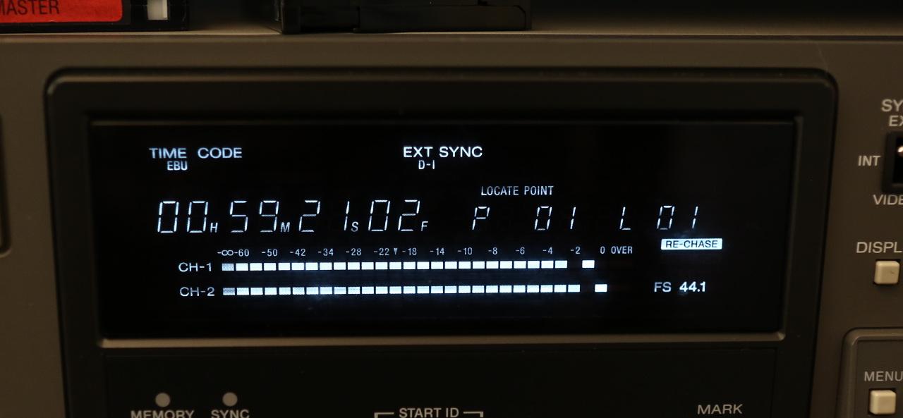
I've been restoring a Sony PCM-7040, which is a professional DAT machine, likely to have been left switched on 24x7 in a recording studio for much of its life. Its display is quite tired (see photo), though the segments relating to features that I presume were't used much are still bright and clear. For example, the "EXT SYNC" and "44.1" indicators are fine, but the "TIME CODE" and "LOCATE POINT" symbols are very dim, and not even uniformly so.
Any suggestions, other than trying to find a similar machine for spares?
-
#22 Reply
Posted by
floobydust
on 11 Dec, 2017 20:32
-
If particular segments are dimmer, then I'd guess it's the phosphor that has aged. It maybe the cathode is locally worn out? That is, low emission over that segment area, but this is a straw I am grasping at.
All we can do so far, is overheat the filament for a short while, say 60sec to "burn off" undesirables from the cathode.
For ideas, it may be worthwhile to look at CRT rejuvenators, such as
B&K Model 490. In that era, many patents etc. as it was big money compared to replacing the CRT.
A VFD has a directly-heated cathode though.
Technique seems to be apply high voltage on the filaments, and also high positive G1-K voltage, with high risk.
B&K's patent here is to heat up the cathode, then simultaneously switch off the filament while then applying high +ve V to G1 for I think max. cathode current.
They say "dust" inside the tube deposits on the cathode and must be burned off. If the cathode is worn out, depleted of barium oxide, nothing can be done.
-
#23 Reply
Posted by
james_s
on 11 Dec, 2017 23:53
-
Yes what you're seeing is the equivalent of phosphor burn on a CRT, there's nothing you can do about it unless you want to wear out the brighter segments to match. Years of being hammered by electrons takes its toll on the phosphors and they work less effectively.
My microwave oven displays the clock on the middle 4 segments of a larger VFD and now those segments are substantially dimmer than the others that light up when I use the timer and other functions.
-
#24 Reply
Posted by
calexanian
on 13 Dec, 2017 19:17
-
Very good. Now let me tell you what is happening.
In VFD displays there is a nickel alloy wire filament that is coated with barium and strontium oxide powder that serves as the emission source. At the boundary of the nickel and the oxide coating certain dopants (Aluminum, titanium, carbon, magnesium, etc) in the nickel will reduce the oxide to metallic barium and strontium and the low work functions of these metals are what give you your emission. This happens extremely slowly at normal cathode temperature of say 850 C to 950 C and during tube manufacturing the temp is raised to neat 100 C for nearly a minute depending on cathode size to speed this process. In VFD tubes the emission requirement is so low that they are run at minimum filament voltage. This also reduces the sight of the glowing filament which would interfere with he lit digit glow. At these reduced voltages that reducing effect can be weak and insufficient barium can remain to emit due to barium sublimation. Temporary raising the filament temperature or "Flashing" can restore this process and provide new barium and increase emission. This is a loosing battle however. you can typically only do it once or twice before you run out of viable material or poison the filament. As far as over voltage I cannot comment as I do not know the composition of what is in your particular VFD. In general nickel filaments are run to near yellow heat in the initial breakdown process and that occurs at about double filament voltage. I have seen literature that suggests %150 filament voltage is typical for a minute or so in rejuvenation processes. you don't want it to go much past light orange hot though for risk of it melting. You could also just bump up the filament voltage %10 and just let it fly. you may see the glow more from the filaments but it will defiantly increase emission. You are living on borrowed time at this point anyways.
Just my two cents.