-
KickStarter: High Accuracy Programmable & Cute Resistance Substitution Box
Posted by frankli on 17 Jul, 2022 20:44 -
Dear All,
Yesterday we launched a revolutionary product, New Generation Resistance Substitution Box, in Kickstarter:
https://www.kickstarter.com/projects/eastwoodtech/qr10-pocket-high-accuracy-programmable-resistance-box?ref=discovery&term=QR10
Please allow me to use this platform to recommend the product which can be potentially beneficial to some readers here.
Unlike it's conventional counterpart, QR10 replaced the rotary switches with an OLED, keypad and RF relays. It can be controlled by any free serial software via USB-COM port. Hence it's very suitable for applications like auto-test, auto-calibration and (RTD) sensor simulation.
Moreover, the accuracy can reach ±0.01% , ranges can cover 1 Ω - 8.4 MΩ and the price (Kickstarter special, 30% OFF) is only 10%~20% of its competitors. You can visit our website WWW.EASTWOOD.TECH to get QR10's datasheet and user manual.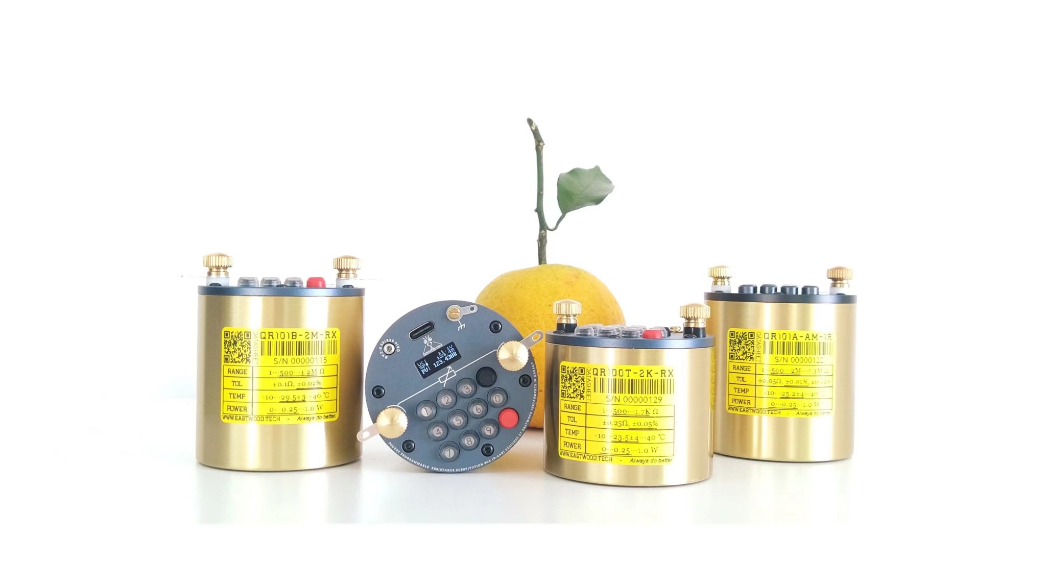
Should you have any questions or wish to know more about the product, please feel free to ask here, Kickstarter, or email us via eastwood.tech@outlook.com. Your comments and feedback on the product are highly appreciated!
If you are a social media influencer and would like to give us a thorough technical product review, please contact us.
-
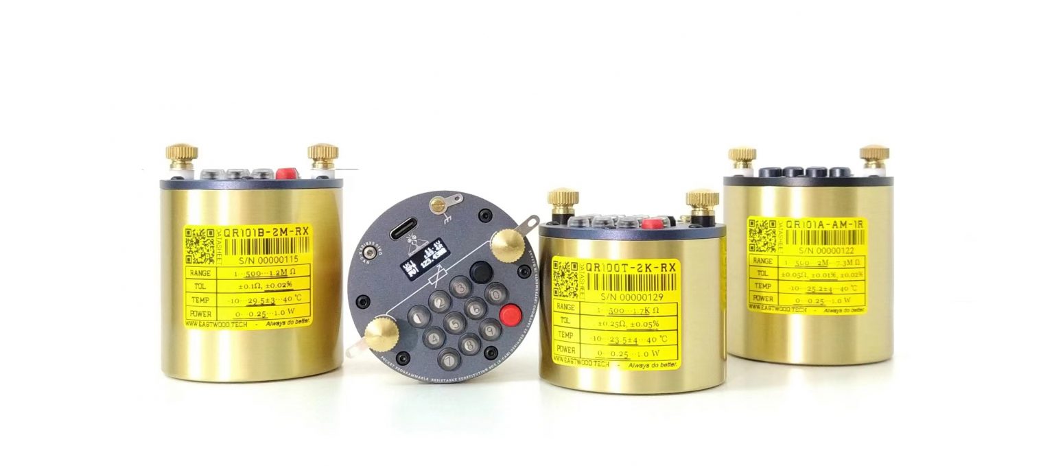
More pics:
Comparison with similiar products: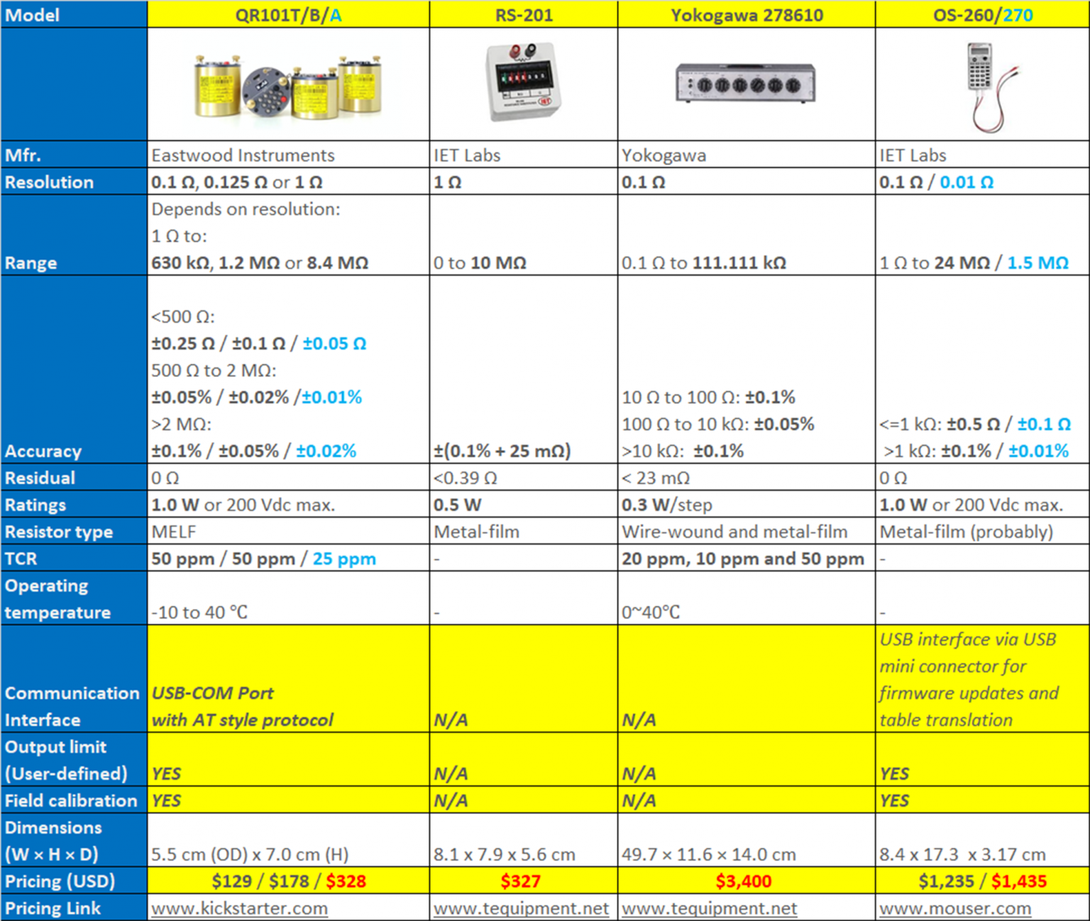
aging tests: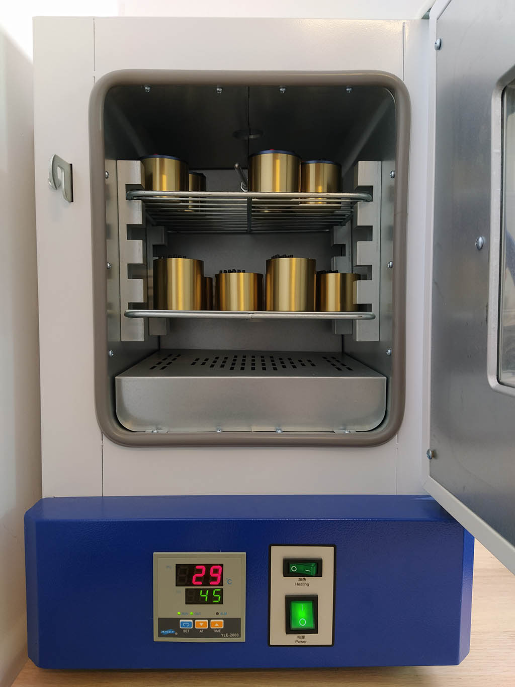
-
Dear All,
Yesterday we launched a new product, New Generation Resistance Substitution Box, in Kickstarter:
https://www.kickstarter.com/projects/eastwoodtech/qr10-pocket-high-accuracy-programmable-resistance-box?ref=discovery&term=QR10
Your comments and professional opinions are highly appreciated!
Unlike it's conventional counterpart, QR10 replaced the rotary switches with an OLED, keypad and RF relays. It can be controlled by any free serial software via USB-COM port. Hence it's very suitable for applications like auto-test, auto-calibration and (RTD) sensor simulation.
Moreover, the accuracy can reach ±0.01% , ranges can cover 1 Ω - 8.4 MΩ and the price (Kickstarter special, 30% OFF) is only 10%~20% of its competitors. You can visit our website WWW.EASTWOOD.TECH to get QR10's datasheet and user manual.
Should you have any questions or wish to know more about the product, please feel free to ask here, Kickstarter, or email us via eastwood.tech@outlook.com. Your comments and feedback on the product are highly appreciated!
If you are a social media influencer and would like to give us a thorough technical product review, please contact us.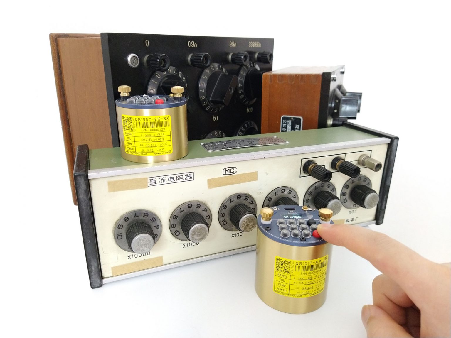
-
So, it is a number resistors in series between the two terminals, with a relay in parallel with a resistor to short the resistor.
Please explain in words of one syllable how this enables a residual resistance of 0ohms. Your analysis should include the diameter+lenght of the wire between the terminals and each resistor, and the contact resistance of the relay. -
That's a very cool form factor. But I suspect it's too cool for the automated production stuff you had in mind which would dictate say a small 1U rack compaitable type case.
-
Why on earth would you use binding posts that can’t accept banana plugs?!? That alone would be a deal-breaker for me. Ideally, binding posts that accept wire as well as both standard and sheathed (safety) banana plugs. Hard to find but do exist.
-
Hi tggzzz,
Thanks for the questions!
The answer to the 1st one: Yes, different models have different configuration of registers and relays.
The 2nd one: QR10 uses a more elegant and accurate way to handle the "residual resistance" than traditional Resistance Decade Box. This is also one of the advantages of QR10.
QR10 has an MCU to control the relay coil of "Relay-Resistor Network". When user set 10 Ω, and we already know (measured) the relay contact resistance and the PCB routing resistance is, say 0.5 Ω. Then we offset this 0.5 Ω in advance and set the switch to produce 9.5 Ω. -
+1
these plugs surely exist.
Leaving this connection as it is will "force" the user to take adapters which increasing the contact resistance, besides the more time you must spend for doing connections.
Apart from this: Nice thing. -
@OP you started two threads in two subforums about the same product, this is becoming confusing, you can request Mods to merge the topic to a single thread.
-
Dear Admin,
QR10 is mainly for individuals like electrical hobbyists, engineers and students. As for industrial application, it's surely capable of (accurate, has a big range & powerful), but it's not what it was originally designed for.
btw, if you need a freesample to test and teardown and publish the test results to pulic, let us know? -
Hi Bud,
not sure about the regulations here. If needed, I can delete the post in testgear. -
Hi Bud,
not sure about the regulations here. If needed, I can delete the post in testgear.
Yes please. We don't allow duplicate posting here. -
@tooki & @Martin72,
Thanks for your comments on banana plugs. Due to the limition of panel space, our earlier versions have to choose the 2mm banana plugs (Female) and we also refered Nokia's key-key space design to place the 3x4 keypad within the OD 55 mm panel.
We also did tried almost all types of 4mm banana plugs on the market, not surprised they either have conflict with the keys or narrow down the keys border free space, or, just ugly.
Some pics of our earlier designs about the plugs:
https://drive.google.com/drive/folders/13caHkl--binL1iB12tYrjHhdAIhbBw0l?usp=sharing -
It is an interesting take on a programmable resistor, but I do not like the serial protocol.
It may work fine for control from a terminal, but for control from a program I would prefer it more simple and SCPI like. I would probably be possible to have a extra command set for that.
Something like:
Set resistance value, will not return any answer: set xxx
Asked current resistance value, will return one number with a CR LF termination: set?
And maybe a few more command to read the other values, but no multi line return values. Multiple values can be return as "value1 value2 value3 CR LF", i.e. with spaces between and no text. -
There is a review on the Chinese web site which include some testing. You may need to use google translate to navigate through.
https://bbs.elecfans.com/jishu_2291086_1_1.html -
Hi tggzzz,
Thanks for the questions!
The answer to the 1st one: Yes, different models have different configuration of registers and relays.
The 2nd one: QR10 uses a more elegant and accurate way to handle the "residual resistance" than traditional Resistance Decade Box. This is also one of the advantages of QR10.
QR10 has an MCU to control the relay coil of "Relay-Resistor Network". When user set 10 Ω, and we already know (measured) the relay contact resistance and the PCB routing resistance is, say 0.5 Ω. Then we offset this 0.5 Ω in advance and set the switch to produce 9.5 Ω.
That allows a zero differential resistance under some conditions, but you claim a zero residual resistance.
Presume you have entered the offset values, and selected 0ohms. To use hypothetical numbers, if there is 0.01ohms resistance in the wires and 0.01ohms resistance in each of 9 relays, then the resistance between the terminals would be 0.1ohms, not the 0ohms you claim. Hence the residual resistance would be 0.1ohms, not 0ohms.
What is the specification for the relay contact changes over time, e.g. after 10000 operations, and with relay orientation?
What is the specification for the relay contact changes with changing relay orientation?
That will determine how the well calibrated your device remains.
If you are producing something aimed at hobbyists, then your device may well be sufficient. But you are comparing it with high quality standard resistors, and your comparisons appear invalid and statements incorrect. I am willing to be convinced otherwise.
-
It is an interesting take on a programmable resistor, but I do not like the serial protocol.
It may work fine for control from a terminal, but for control from a program I would prefer it more simple and SCPI like. I would probably be possible to have a extra command set for that.
Something like:
Set resistance value, will not return any answer: set xxx
Asked current resistance value, will return one number with a CR LF termination: set?
And maybe a few more command to read the other values, but no multi line return values. Multiple values can be return as "value1 value2 value3 CR LF", i.e. with spaces between and no text.
I agree. The current protocol implementation would require quite a bit of coding to properly parse responses, compared to single line responses (even ignoring error handling).
Simplifying the protocol will almost certainly make it simpler to implement at both ends, and thus may free up some precious mcu resources for other features.That allows a zero differential resistance under some conditions, but you claim a zero residual resistance.
Presume you have entered the offset values, and selected 0ohms. To use hypothetical numbers, if there is 0.01ohms resistance in the wires and 0.01ohms resistance in each of 9 relays, then the resistance between the terminals would be 0.1ohms, not the 0ohms you claim. Hence the residual resistance would be 0.1ohms, not 0ohms.
The minimum selected resistance is 1 ohm, even on the models that have a 0.1ohm step and smaller range. This allows them room to compensate for those internal resistances.
-
Hi,
I do found a QR10 unpacking video shot with decent camera:
https://www.bilibili.com/video/BV1ka411D7NS
CC -
Hi tggzzz,
Thanks for the questions!
The answer to the 1st one: Yes, different models have different configuration of registers and relays.
The 2nd one: QR10 uses a more elegant and accurate way to handle the "residual resistance" than traditional Resistance Decade Box. This is also one of the advantages of QR10.
QR10 has an MCU to control the relay coil of "Relay-Resistor Network". When user set 10 Ω, and we already know (measured) the relay contact resistance and the PCB routing resistance is, say 0.5 Ω. Then we offset this 0.5 Ω in advance and set the switch to produce 9.5 Ω.
That allows a zero differential resistance under some conditions, but you claim a zero residual resistance.
Presume you have entered the offset values, and selected 0ohms. To use hypothetical numbers, if there is 0.01ohms resistance in the wires and 0.01ohms resistance in each of 9 relays, then the resistance between the terminals would be 0.1ohms, not the 0ohms you claim. Hence the residual resistance would be 0.1ohms, not 0ohms.
What is the specification for the relay contact changes over time, e.g. after 10000 operations, and with relay orientation?
What is the specification for the relay contact changes with changing relay orientation?
That will determine how the well calibrated your device remains.
If you are producing something aimed at hobbyists, then your device may well be sufficient. But you are comparing it with high quality standard resistors, and your comparisons appear invalid and statements incorrect. I am willing to be convinced otherwise.
Hi tggzzz,
I'm CC, Frank's colleague. Since he is in bed right now, allow me to answer your question.
1. The concept of “residual resistance” you mentioned is actually from the old fashined resistance box for that it can do nothing about cable resistance and switch contact resistance. While for QR10, we can re-define residual resistance as “0” for the reason it was already included in the output PV (we measured it in advance and based on it to decide “Relay-resistor” combination value).
2. For relay performance, we did a lot test in our EVT 125 units and found it's much stable than the specification given. If you want to see the original data, just send us an email to eastwood.tech@outlook.com
3. The relay we choosed is not liquid type. No such limitation in orientation.
4. QR10 is for hobbyists, but it doesn't mean low quality and shit. And it's for general purpose application rather than "resistance standard" - we will charge you 10 times more if it is.
Thanks for your question, appreciate it indeed!
Best,
CC
-
Hi tggzzz,
Thanks for the questions!
The answer to the 1st one: Yes, different models have different configuration of registers and relays.
The 2nd one: QR10 uses a more elegant and accurate way to handle the "residual resistance" than traditional Resistance Decade Box. This is also one of the advantages of QR10.
QR10 has an MCU to control the relay coil of "Relay-Resistor Network". When user set 10 Ω, and we already know (measured) the relay contact resistance and the PCB routing resistance is, say 0.5 Ω. Then we offset this 0.5 Ω in advance and set the switch to produce 9.5 Ω.
That allows a zero differential resistance under some conditions, but you claim a zero residual resistance.
Presume you have entered the offset values, and selected 0ohms. To use hypothetical numbers, if there is 0.01ohms resistance in the wires and 0.01ohms resistance in each of 9 relays, then the resistance between the terminals would be 0.1ohms, not the 0ohms you claim. Hence the residual resistance would be 0.1ohms, not 0ohms.
What is the specification for the relay contact changes over time, e.g. after 10000 operations, and with relay orientation?
What is the specification for the relay contact changes with changing relay orientation?
That will determine how the well calibrated your device remains.
If you are producing something aimed at hobbyists, then your device may well be sufficient. But you are comparing it with high quality standard resistors, and your comparisons appear invalid and statements incorrect. I am willing to be convinced otherwise.
Hi tggzzz,
I'm CC, Frank's colleague. Since he is in bed right now, allow me to answer your question.
1. The concept of “residual resistance” you mentioned is actually from the old fashined resistance box for that it can do nothing about cable resistance and switch contact resistance. While for QR10, we can re-define residual resistance as “0”
Nonsense: you can't simply re-define a standard techincal term to suit your marketing.
Or, if you can, then the concept of "web forum" is from the old-fashioned web 1.0, and I can redefine EEVBlog Forum as a "usenet forum".
Or perhaps I can define that a car "floats" on water, because with the doors shut it takes quite a few seconds before the water is up to the windows.
Any and all of those redefinitions are crap designed to confuse and hide.
If a user can't select 0ohms, put a current through your device and measure zero volts across the terminals, then the residual resistance isn't zero ohms.
Simply state the minimum resistance between the terminals, and state the increments you can set on top of that minimum resistance. Anything else is deliberately deceptive.Quotefor the reason it was already included in the output PV (we measured it in advance and based on it to decide “Relay-resistor” combination value).
What is "PV" or "process value"?
I guess it means incremental resistance. But nobody cares what my guess is.
Please stop creating datasheets using cheese[1]
[1] my definition of cheese is a computer program that enables creation of written documents! Stupid? No more than your inventing terms!
Quote2. For relay performance, we did a lot test in our EVT 125 units and found it's much stable than the specification given. If you want to see the original data, just send us an email to eastwood.tech@outlook.com
Nobody cares about your measurements; they could be flukes or badly implemented.
The next batch of relays might be very different. The same batch might have a very different measurement next week. And nobody could complain.Quote3. The relay we choosed is not liquid type. No such limitation in orientation.
Is that guaranteed by the specification or by you not finding any issue yesterday?Quote4. QR10 is for hobbyists, but it doesn't mean low quality and shit. And it's for general purpose application rather than "resistance standard" - we will charge you 10 times more if it is.
Thanks for your question, appreciate it indeed!
Nothing wrong with it being general purpose, but don't compare it to standard resistors.
I wouldn't compare a Toyota Yaris to a Rolls Royce.
Hi tggzz,
I'm afraid you wend too, FAR. Return and talk in peace, please.
1. Timing and tide is changing and you must accept it. Science and technique is not Bible that can not be modified (for Bibile, who knows:-).
If you don't agree with me, I guess IET Labs can answer your same question about “residual resistance” (here is the link: https://www.ietlabs.com/os-260-resistance-decade-box-rtd-simulator.html). Great minds think alike - I mean, us - Eastwood Instruments and IET labs.
2. If you want to know the relay model, the best way is to order one (or you can apply for a free sample on our official website), tear it down and see. What I can tell you is, the relay brand we selected is from JP. I seldom question our friendly neighbor's quality control. But sure, you can.
3. We all born equal (@admin, this is not talking about politics, please), and the remarkable thing of instruments field is, there is an objective "standard" and even the tiny one can be a gaint.
Why not order one and see? I'll give you a big bargain since we almost be friends already.
Best,
CC
-
Hi tggzzz,
Thanks for the questions!
The answer to the 1st one: Yes, different models have different configuration of registers and relays.
The 2nd one: QR10 uses a more elegant and accurate way to handle the "residual resistance" than traditional Resistance Decade Box. This is also one of the advantages of QR10.
QR10 has an MCU to control the relay coil of "Relay-Resistor Network". When user set 10 Ω, and we already know (measured) the relay contact resistance and the PCB routing resistance is, say 0.5 Ω. Then we offset this 0.5 Ω in advance and set the switch to produce 9.5 Ω.
That allows a zero differential resistance under some conditions, but you claim a zero residual resistance.
Presume you have entered the offset values, and selected 0ohms. To use hypothetical numbers, if there is 0.01ohms resistance in the wires and 0.01ohms resistance in each of 9 relays, then the resistance between the terminals would be 0.1ohms, not the 0ohms you claim. Hence the residual resistance would be 0.1ohms, not 0ohms.
What is the specification for the relay contact changes over time, e.g. after 10000 operations, and with relay orientation?
What is the specification for the relay contact changes with changing relay orientation?
That will determine how the well calibrated your device remains.
If you are producing something aimed at hobbyists, then your device may well be sufficient. But you are comparing it with high quality standard resistors, and your comparisons appear invalid and statements incorrect. I am willing to be convinced otherwise.
Hi tggzzz,
I'm CC, Frank's colleague. Since he is in bed right now, allow me to answer your question.
1. The concept of “residual resistance” you mentioned is actually from the old fashined resistance box for that it can do nothing about cable resistance and switch contact resistance. While for QR10, we can re-define residual resistance as “0”
Nonsense: you can't simply re-define a standard techincal term to suit your marketing.
Or, if you can, then the concept of "web forum" is from the old-fashioned web 1.0, and I can redefine EEVBlog Forum as a "usenet forum".
Or perhaps I can define that a car "floats" on water, because with the doors shut it takes quite a few seconds before the water is up to the windows.
Any and all of those redefinitions are crap designed to confuse and hide.
If a user can't select 0ohms, put a current through your device and measure zero volts across the terminals, then the residual resistance isn't zero ohms.
Simply state the minimum resistance between the terminals, and state the increments you can set on top of that minimum resistance. Anything else is deliberately deceptive.Quotefor the reason it was already included in the output PV (we measured it in advance and based on it to decide “Relay-resistor” combination value).
What is "PV" or "process value"?
I guess it means incremental resistance. But nobody cares what my guess is.
Please stop creating datasheets using cheese[1]
[1] my definition of cheese is a computer program that enables creation of written documents! Stupid? No more than your inventing terms!
Quote2. For relay performance, we did a lot test in our EVT 125 units and found it's much stable than the specification given. If you want to see the original data, just send us an email to eastwood.tech@outlook.com
Nobody cares about your measurements; they could be flukes or badly implemented.
The next batch of relays might be very different. The same batch might have a very different measurement next week. And nobody could complain.Quote3. The relay we choosed is not liquid type. No such limitation in orientation.
Is that guaranteed by the specification or by you not finding any issue yesterday?Quote4. QR10 is for hobbyists, but it doesn't mean low quality and shit. And it's for general purpose application rather than "resistance standard" - we will charge you 10 times more if it is.
Thanks for your question, appreciate it indeed!
Nothing wrong with it being general purpose, but don't compare it to standard resistors.
I wouldn't compare a Toyota Yaris to a Rolls Royce.
Hi tggzz,
I'm afraid you wend too, FAR. Return and talk in peace, please.
1. Timing and tide is changing and you must accept it. Science and technique is not Bible that can not be modified (for Bibile, who knows:-).
If you don't agree with me, I guess IET Labs can answer your same question about “residual resistance” (here is the link: https://www.ietlabs.com/os-260-resistance-decade-box-rtd-simulator.html). Great minds think alike - I mean, us - Eastwood Instruments and IET labs.
2. If you want to know the relay model, the best way is to order one (or you can apply for a free sample on our official website), tear it down and see. What I can tell you is, the relay brand we selected is from JP. I seldom question our friendly neighbor's quality control. But sure, you can.
3. We all born equal (@admin, this is not talking about politics, please), and the remarkable thing of instruments field is, there is an objective "standard" and even the tiny one can be a gaint.
Why not order one and see? I'll give you a big bargain since we almost be friends already.
Best,
CC
Firstly and obviously, when you make claims about your device, it is up to you to justify them - not other people to dispove them.
Secondly and more importantly, I and most other engineers, strongly dislike Wittgenstein-style "language games".
Basically your (rather weird) response about un-birthday presents is a glory...Quote from: Through the Looking-Glass by Lewis Carroll, Ch7
[Humpty Dumpty:] 'And only ONE for birthday presents, you know. There's glory for you!'
'I don't know what you mean by "glory,"' Alice said.
Humpty Dumpty smiled contemptuously. 'Of course you don't--till I tell you. I meant "there's a nice knock-down argument for you!"'
'But "glory" doesn't mean "a nice knock-down argument,"' Alice objected.
'When _I_ use a word,' Humpty Dumpty said in rather a scornful tone, 'it means just what I choose it to mean--neither more nor less.'
'The question is,' said Alice, 'whether you CAN make words mean so many different things.'
'The question is,' said Humpty Dumpty, 'which is to be master--that's all.' -
Your comments and professional opinions are highly appreciated!
It looks interesting but I'm not sure why you felt it necessary to make it so small?
I see your colleague has stepped on a land mine by getting into a debate between compensating for and eliminating residual resistance. It seems obvious what you've done there and it is a good idea, but being precise in the description is important. I understand what you've done but would need to be convinced that the compensation is valid over time and varying operating conditions. For example, I think you will struggle to meet your TC specs at minimum resistance because the residual that you are compensating for will likely have a larger TC than the resistors themselves. Or perhaps I haven't read the specs closely enough and that's accounted for.
You are welcome to send me an example if you want it tested. I'm not a Youtuber but I'd post the results, photos, etc here. I'm able to measure it to the specs you've given and I'd be comparing it to other old-style resistance substitution boxes like the ESI Dekabox and Ohmite Decade-Ranger. PM if you like.