-
KickStarter: High Accuracy Programmable & Cute Resistance Substitution Box
Posted by frankli on 17 Jul, 2022 20:44 -
Dear All,
Yesterday we launched a revolutionary product, New Generation Resistance Substitution Box, in Kickstarter:
https://www.kickstarter.com/projects/eastwoodtech/qr10-pocket-high-accuracy-programmable-resistance-box?ref=discovery&term=QR10
Please allow me to use this platform to recommend the product which can be potentially beneficial to some readers here.
Unlike it's conventional counterpart, QR10 replaced the rotary switches with an OLED, keypad and RF relays. It can be controlled by any free serial software via USB-COM port. Hence it's very suitable for applications like auto-test, auto-calibration and (RTD) sensor simulation.
Moreover, the accuracy can reach ±0.01% , ranges can cover 1 Ω - 8.4 MΩ and the price (Kickstarter special, 30% OFF) is only 10%~20% of its competitors. You can visit our website WWW.EASTWOOD.TECH to get QR10's datasheet and user manual.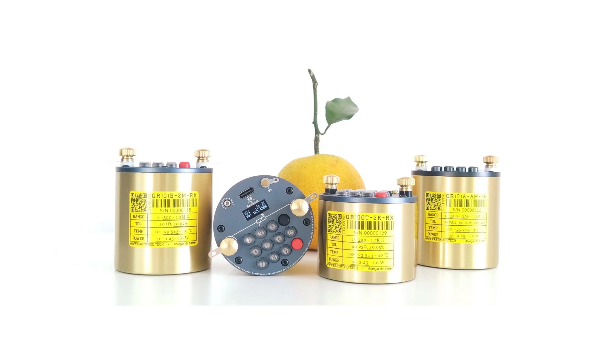
Should you have any questions or wish to know more about the product, please feel free to ask here, Kickstarter, or email us via eastwood.tech@outlook.com. Your comments and feedback on the product are highly appreciated!
If you are a social media influencer and would like to give us a thorough technical product review, please contact us.
-
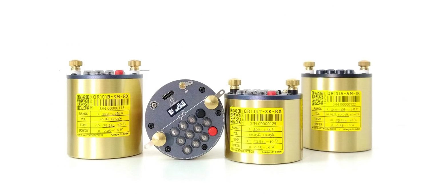
More pics:
Comparison with similiar products: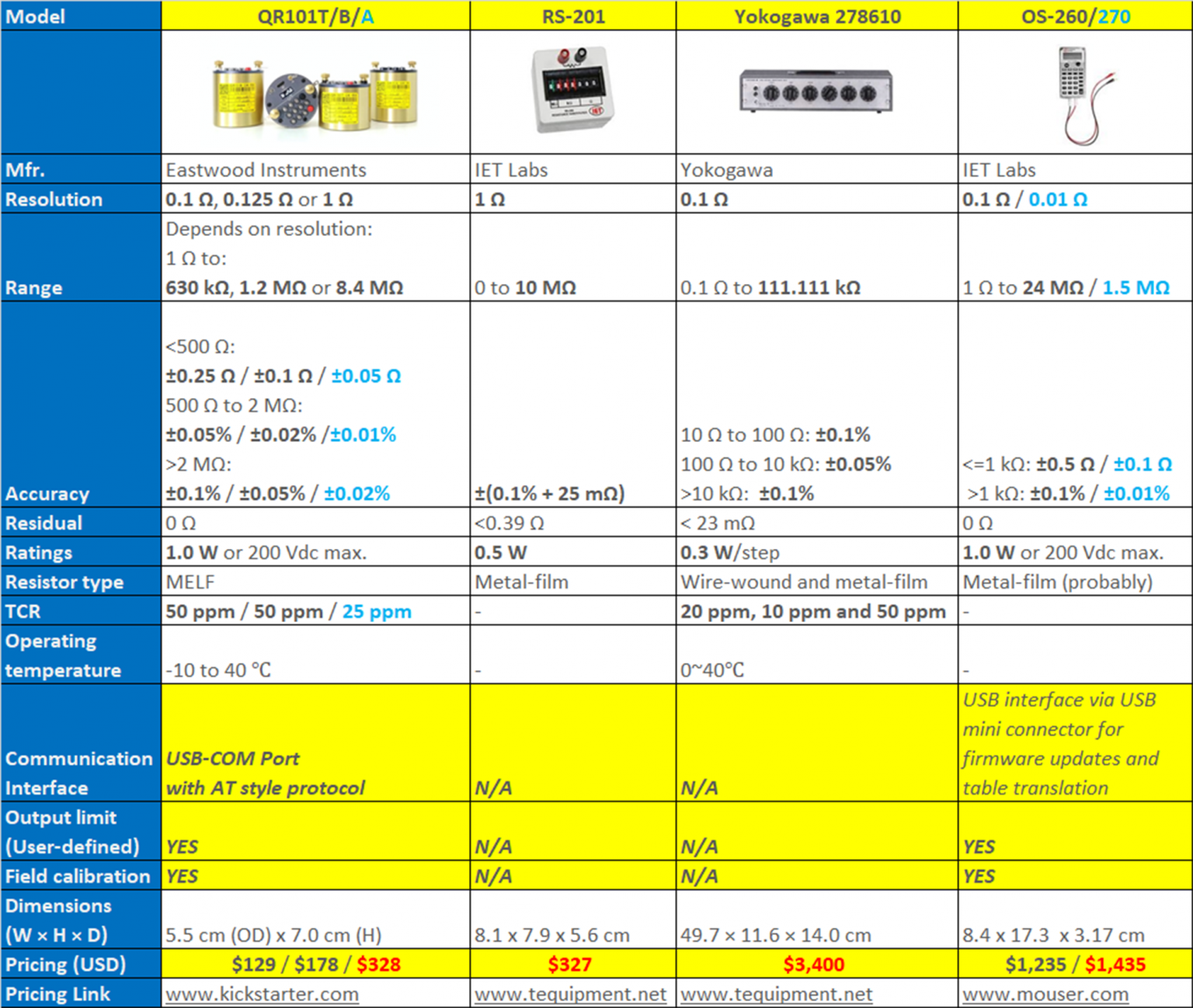
aging tests: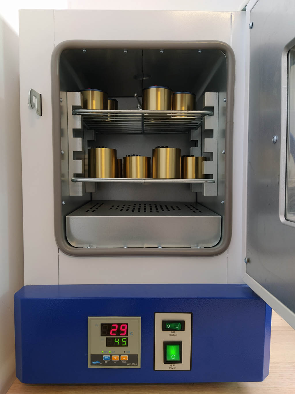
-
Dear All,
Yesterday we launched a new product, New Generation Resistance Substitution Box, in Kickstarter:
https://www.kickstarter.com/projects/eastwoodtech/qr10-pocket-high-accuracy-programmable-resistance-box?ref=discovery&term=QR10
Your comments and professional opinions are highly appreciated!
Unlike it's conventional counterpart, QR10 replaced the rotary switches with an OLED, keypad and RF relays. It can be controlled by any free serial software via USB-COM port. Hence it's very suitable for applications like auto-test, auto-calibration and (RTD) sensor simulation.
Moreover, the accuracy can reach ±0.01% , ranges can cover 1 Ω - 8.4 MΩ and the price (Kickstarter special, 30% OFF) is only 10%~20% of its competitors. You can visit our website WWW.EASTWOOD.TECH to get QR10's datasheet and user manual.
Should you have any questions or wish to know more about the product, please feel free to ask here, Kickstarter, or email us via eastwood.tech@outlook.com. Your comments and feedback on the product are highly appreciated!
If you are a social media influencer and would like to give us a thorough technical product review, please contact us.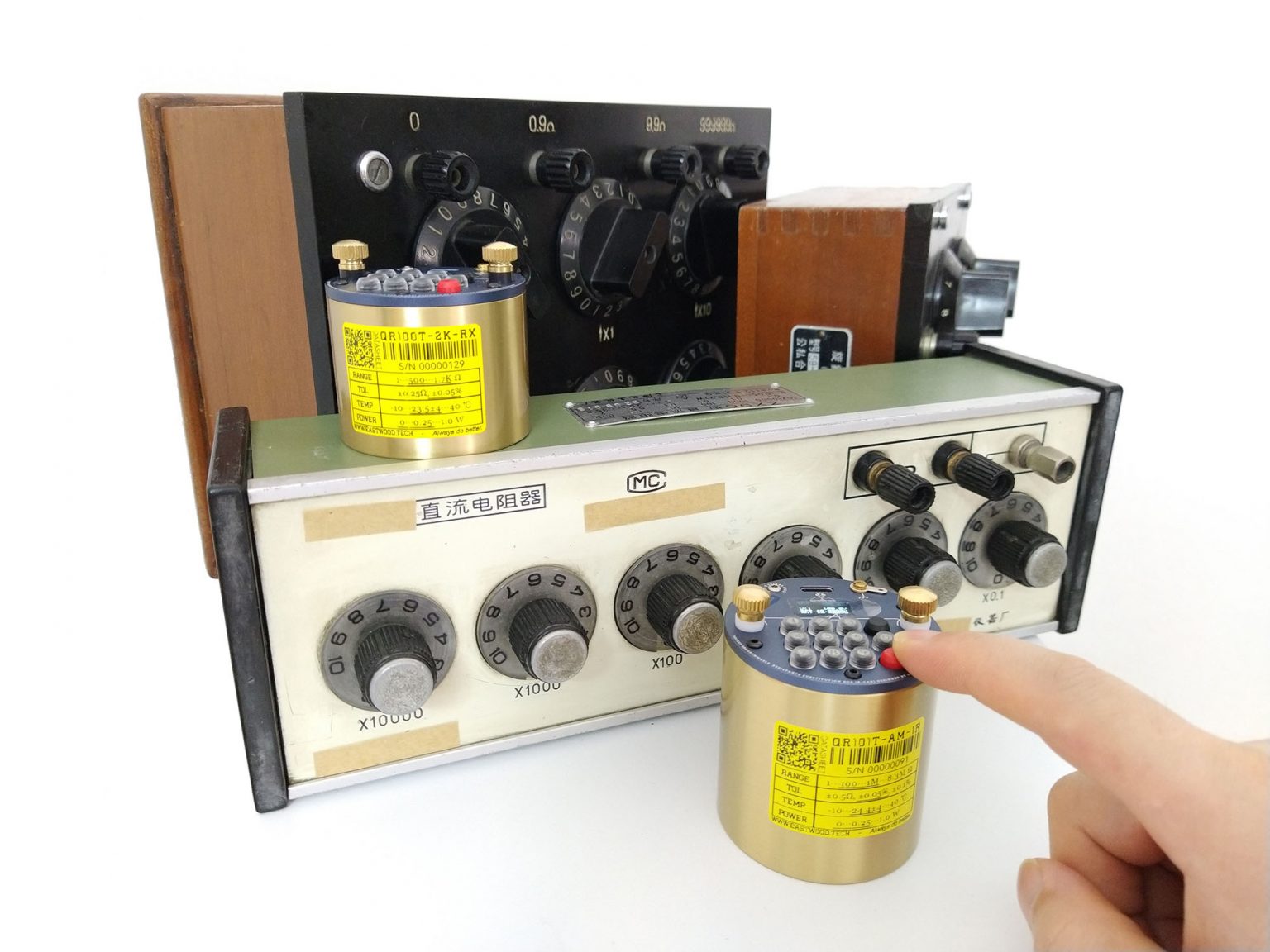
-
So, it is a number resistors in series between the two terminals, with a relay in parallel with a resistor to short the resistor.
Please explain in words of one syllable how this enables a residual resistance of 0ohms. Your analysis should include the diameter+lenght of the wire between the terminals and each resistor, and the contact resistance of the relay. -
That's a very cool form factor. But I suspect it's too cool for the automated production stuff you had in mind which would dictate say a small 1U rack compaitable type case.
-
Why on earth would you use binding posts that can’t accept banana plugs?!? That alone would be a deal-breaker for me. Ideally, binding posts that accept wire as well as both standard and sheathed (safety) banana plugs. Hard to find but do exist.
-
Hi tggzzz,
Thanks for the questions!
The answer to the 1st one: Yes, different models have different configuration of registers and relays.
The 2nd one: QR10 uses a more elegant and accurate way to handle the "residual resistance" than traditional Resistance Decade Box. This is also one of the advantages of QR10.
QR10 has an MCU to control the relay coil of "Relay-Resistor Network". When user set 10 Ω, and we already know (measured) the relay contact resistance and the PCB routing resistance is, say 0.5 Ω. Then we offset this 0.5 Ω in advance and set the switch to produce 9.5 Ω. -
+1
these plugs surely exist.
Leaving this connection as it is will "force" the user to take adapters which increasing the contact resistance, besides the more time you must spend for doing connections.
Apart from this: Nice thing. -
@OP you started two threads in two subforums about the same product, this is becoming confusing, you can request Mods to merge the topic to a single thread.
-
Dear Admin,
QR10 is mainly for individuals like electrical hobbyists, engineers and students. As for industrial application, it's surely capable of (accurate, has a big range & powerful), but it's not what it was originally designed for.
btw, if you need a freesample to test and teardown and publish the test results to pulic, let us know? -
Hi Bud,
not sure about the regulations here. If needed, I can delete the post in testgear. -
Hi Bud,
not sure about the regulations here. If needed, I can delete the post in testgear.
Yes please. We don't allow duplicate posting here. -
@tooki & @Martin72,
Thanks for your comments on banana plugs. Due to the limition of panel space, our earlier versions have to choose the 2mm banana plugs (Female) and we also refered Nokia's key-key space design to place the 3x4 keypad within the OD 55 mm panel.
We also did tried almost all types of 4mm banana plugs on the market, not surprised they either have conflict with the keys or narrow down the keys border free space, or, just ugly.
Some pics of our earlier designs about the plugs:
https://drive.google.com/drive/folders/13caHkl--binL1iB12tYrjHhdAIhbBw0l?usp=sharing -
It is an interesting take on a programmable resistor, but I do not like the serial protocol.
It may work fine for control from a terminal, but for control from a program I would prefer it more simple and SCPI like. I would probably be possible to have a extra command set for that.
Something like:
Set resistance value, will not return any answer: set xxx
Asked current resistance value, will return one number with a CR LF termination: set?
And maybe a few more command to read the other values, but no multi line return values. Multiple values can be return as "value1 value2 value3 CR LF", i.e. with spaces between and no text. -
There is a review on the Chinese web site which include some testing. You may need to use google translate to navigate through.
https://bbs.elecfans.com/jishu_2291086_1_1.html -
Hi tggzzz,
Thanks for the questions!
The answer to the 1st one: Yes, different models have different configuration of registers and relays.
The 2nd one: QR10 uses a more elegant and accurate way to handle the "residual resistance" than traditional Resistance Decade Box. This is also one of the advantages of QR10.
QR10 has an MCU to control the relay coil of "Relay-Resistor Network". When user set 10 Ω, and we already know (measured) the relay contact resistance and the PCB routing resistance is, say 0.5 Ω. Then we offset this 0.5 Ω in advance and set the switch to produce 9.5 Ω.
That allows a zero differential resistance under some conditions, but you claim a zero residual resistance.
Presume you have entered the offset values, and selected 0ohms. To use hypothetical numbers, if there is 0.01ohms resistance in the wires and 0.01ohms resistance in each of 9 relays, then the resistance between the terminals would be 0.1ohms, not the 0ohms you claim. Hence the residual resistance would be 0.1ohms, not 0ohms.
What is the specification for the relay contact changes over time, e.g. after 10000 operations, and with relay orientation?
What is the specification for the relay contact changes with changing relay orientation?
That will determine how the well calibrated your device remains.
If you are producing something aimed at hobbyists, then your device may well be sufficient. But you are comparing it with high quality standard resistors, and your comparisons appear invalid and statements incorrect. I am willing to be convinced otherwise.
-
It is an interesting take on a programmable resistor, but I do not like the serial protocol.
It may work fine for control from a terminal, but for control from a program I would prefer it more simple and SCPI like. I would probably be possible to have a extra command set for that.
Something like:
Set resistance value, will not return any answer: set xxx
Asked current resistance value, will return one number with a CR LF termination: set?
And maybe a few more command to read the other values, but no multi line return values. Multiple values can be return as "value1 value2 value3 CR LF", i.e. with spaces between and no text.
I agree. The current protocol implementation would require quite a bit of coding to properly parse responses, compared to single line responses (even ignoring error handling).
Simplifying the protocol will almost certainly make it simpler to implement at both ends, and thus may free up some precious mcu resources for other features.That allows a zero differential resistance under some conditions, but you claim a zero residual resistance.
Presume you have entered the offset values, and selected 0ohms. To use hypothetical numbers, if there is 0.01ohms resistance in the wires and 0.01ohms resistance in each of 9 relays, then the resistance between the terminals would be 0.1ohms, not the 0ohms you claim. Hence the residual resistance would be 0.1ohms, not 0ohms.
The minimum selected resistance is 1 ohm, even on the models that have a 0.1ohm step and smaller range. This allows them room to compensate for those internal resistances.
-
Hi,
I do found a QR10 unpacking video shot with decent camera:
https://www.bilibili.com/video/BV1ka411D7NS
CC -
Hi tggzzz,
Thanks for the questions!
The answer to the 1st one: Yes, different models have different configuration of registers and relays.
The 2nd one: QR10 uses a more elegant and accurate way to handle the "residual resistance" than traditional Resistance Decade Box. This is also one of the advantages of QR10.
QR10 has an MCU to control the relay coil of "Relay-Resistor Network". When user set 10 Ω, and we already know (measured) the relay contact resistance and the PCB routing resistance is, say 0.5 Ω. Then we offset this 0.5 Ω in advance and set the switch to produce 9.5 Ω.
That allows a zero differential resistance under some conditions, but you claim a zero residual resistance.
Presume you have entered the offset values, and selected 0ohms. To use hypothetical numbers, if there is 0.01ohms resistance in the wires and 0.01ohms resistance in each of 9 relays, then the resistance between the terminals would be 0.1ohms, not the 0ohms you claim. Hence the residual resistance would be 0.1ohms, not 0ohms.
What is the specification for the relay contact changes over time, e.g. after 10000 operations, and with relay orientation?
What is the specification for the relay contact changes with changing relay orientation?
That will determine how the well calibrated your device remains.
If you are producing something aimed at hobbyists, then your device may well be sufficient. But you are comparing it with high quality standard resistors, and your comparisons appear invalid and statements incorrect. I am willing to be convinced otherwise.
Hi tggzzz,
I'm CC, Frank's colleague. Since he is in bed right now, allow me to answer your question.
1. The concept of “residual resistance” you mentioned is actually from the old fashined resistance box for that it can do nothing about cable resistance and switch contact resistance. While for QR10, we can re-define residual resistance as “0” for the reason it was already included in the output PV (we measured it in advance and based on it to decide “Relay-resistor” combination value).
2. For relay performance, we did a lot test in our EVT 125 units and found it's much stable than the specification given. If you want to see the original data, just send us an email to eastwood.tech@outlook.com
3. The relay we choosed is not liquid type. No such limitation in orientation.
4. QR10 is for hobbyists, but it doesn't mean low quality and shit. And it's for general purpose application rather than "resistance standard" - we will charge you 10 times more if it is.
Thanks for your question, appreciate it indeed!
Best,
CC
-
Hi tggzzz,
Thanks for the questions!
The answer to the 1st one: Yes, different models have different configuration of registers and relays.
The 2nd one: QR10 uses a more elegant and accurate way to handle the "residual resistance" than traditional Resistance Decade Box. This is also one of the advantages of QR10.
QR10 has an MCU to control the relay coil of "Relay-Resistor Network". When user set 10 Ω, and we already know (measured) the relay contact resistance and the PCB routing resistance is, say 0.5 Ω. Then we offset this 0.5 Ω in advance and set the switch to produce 9.5 Ω.
That allows a zero differential resistance under some conditions, but you claim a zero residual resistance.
Presume you have entered the offset values, and selected 0ohms. To use hypothetical numbers, if there is 0.01ohms resistance in the wires and 0.01ohms resistance in each of 9 relays, then the resistance between the terminals would be 0.1ohms, not the 0ohms you claim. Hence the residual resistance would be 0.1ohms, not 0ohms.
What is the specification for the relay contact changes over time, e.g. after 10000 operations, and with relay orientation?
What is the specification for the relay contact changes with changing relay orientation?
That will determine how the well calibrated your device remains.
If you are producing something aimed at hobbyists, then your device may well be sufficient. But you are comparing it with high quality standard resistors, and your comparisons appear invalid and statements incorrect. I am willing to be convinced otherwise.
Hi tggzzz,
I'm CC, Frank's colleague. Since he is in bed right now, allow me to answer your question.
1. The concept of “residual resistance” you mentioned is actually from the old fashined resistance box for that it can do nothing about cable resistance and switch contact resistance. While for QR10, we can re-define residual resistance as “0”
Nonsense: you can't simply re-define a standard techincal term to suit your marketing.
Or, if you can, then the concept of "web forum" is from the old-fashioned web 1.0, and I can redefine EEVBlog Forum as a "usenet forum".
Or perhaps I can define that a car "floats" on water, because with the doors shut it takes quite a few seconds before the water is up to the windows.
Any and all of those redefinitions are crap designed to confuse and hide.
If a user can't select 0ohms, put a current through your device and measure zero volts across the terminals, then the residual resistance isn't zero ohms.
Simply state the minimum resistance between the terminals, and state the increments you can set on top of that minimum resistance. Anything else is deliberately deceptive.Quotefor the reason it was already included in the output PV (we measured it in advance and based on it to decide “Relay-resistor” combination value).
What is "PV" or "process value"?
I guess it means incremental resistance. But nobody cares what my guess is.
Please stop creating datasheets using cheese[1]
[1] my definition of cheese is a computer program that enables creation of written documents! Stupid? No more than your inventing terms!
Quote2. For relay performance, we did a lot test in our EVT 125 units and found it's much stable than the specification given. If you want to see the original data, just send us an email to eastwood.tech@outlook.com
Nobody cares about your measurements; they could be flukes or badly implemented.
The next batch of relays might be very different. The same batch might have a very different measurement next week. And nobody could complain.Quote3. The relay we choosed is not liquid type. No such limitation in orientation.
Is that guaranteed by the specification or by you not finding any issue yesterday?Quote4. QR10 is for hobbyists, but it doesn't mean low quality and shit. And it's for general purpose application rather than "resistance standard" - we will charge you 10 times more if it is.
Thanks for your question, appreciate it indeed!
Nothing wrong with it being general purpose, but don't compare it to standard resistors.
I wouldn't compare a Toyota Yaris to a Rolls Royce.
Hi tggzz,
I'm afraid you wend too, FAR. Return and talk in peace, please.
1. Timing and tide is changing and you must accept it. Science and technique is not Bible that can not be modified (for Bibile, who knows:-).
If you don't agree with me, I guess IET Labs can answer your same question about “residual resistance” (here is the link: https://www.ietlabs.com/os-260-resistance-decade-box-rtd-simulator.html). Great minds think alike - I mean, us - Eastwood Instruments and IET labs.
2. If you want to know the relay model, the best way is to order one (or you can apply for a free sample on our official website), tear it down and see. What I can tell you is, the relay brand we selected is from JP. I seldom question our friendly neighbor's quality control. But sure, you can.
3. We all born equal (@admin, this is not talking about politics, please), and the remarkable thing of instruments field is, there is an objective "standard" and even the tiny one can be a gaint.
Why not order one and see? I'll give you a big bargain since we almost be friends already.
Best,
CC
-
Hi tggzzz,
Thanks for the questions!
The answer to the 1st one: Yes, different models have different configuration of registers and relays.
The 2nd one: QR10 uses a more elegant and accurate way to handle the "residual resistance" than traditional Resistance Decade Box. This is also one of the advantages of QR10.
QR10 has an MCU to control the relay coil of "Relay-Resistor Network". When user set 10 Ω, and we already know (measured) the relay contact resistance and the PCB routing resistance is, say 0.5 Ω. Then we offset this 0.5 Ω in advance and set the switch to produce 9.5 Ω.
That allows a zero differential resistance under some conditions, but you claim a zero residual resistance.
Presume you have entered the offset values, and selected 0ohms. To use hypothetical numbers, if there is 0.01ohms resistance in the wires and 0.01ohms resistance in each of 9 relays, then the resistance between the terminals would be 0.1ohms, not the 0ohms you claim. Hence the residual resistance would be 0.1ohms, not 0ohms.
What is the specification for the relay contact changes over time, e.g. after 10000 operations, and with relay orientation?
What is the specification for the relay contact changes with changing relay orientation?
That will determine how the well calibrated your device remains.
If you are producing something aimed at hobbyists, then your device may well be sufficient. But you are comparing it with high quality standard resistors, and your comparisons appear invalid and statements incorrect. I am willing to be convinced otherwise.
Hi tggzzz,
I'm CC, Frank's colleague. Since he is in bed right now, allow me to answer your question.
1. The concept of “residual resistance” you mentioned is actually from the old fashined resistance box for that it can do nothing about cable resistance and switch contact resistance. While for QR10, we can re-define residual resistance as “0”
Nonsense: you can't simply re-define a standard techincal term to suit your marketing.
Or, if you can, then the concept of "web forum" is from the old-fashioned web 1.0, and I can redefine EEVBlog Forum as a "usenet forum".
Or perhaps I can define that a car "floats" on water, because with the doors shut it takes quite a few seconds before the water is up to the windows.
Any and all of those redefinitions are crap designed to confuse and hide.
If a user can't select 0ohms, put a current through your device and measure zero volts across the terminals, then the residual resistance isn't zero ohms.
Simply state the minimum resistance between the terminals, and state the increments you can set on top of that minimum resistance. Anything else is deliberately deceptive.Quotefor the reason it was already included in the output PV (we measured it in advance and based on it to decide “Relay-resistor” combination value).
What is "PV" or "process value"?
I guess it means incremental resistance. But nobody cares what my guess is.
Please stop creating datasheets using cheese[1]
[1] my definition of cheese is a computer program that enables creation of written documents! Stupid? No more than your inventing terms!
Quote2. For relay performance, we did a lot test in our EVT 125 units and found it's much stable than the specification given. If you want to see the original data, just send us an email to eastwood.tech@outlook.com
Nobody cares about your measurements; they could be flukes or badly implemented.
The next batch of relays might be very different. The same batch might have a very different measurement next week. And nobody could complain.Quote3. The relay we choosed is not liquid type. No such limitation in orientation.
Is that guaranteed by the specification or by you not finding any issue yesterday?Quote4. QR10 is for hobbyists, but it doesn't mean low quality and shit. And it's for general purpose application rather than "resistance standard" - we will charge you 10 times more if it is.
Thanks for your question, appreciate it indeed!
Nothing wrong with it being general purpose, but don't compare it to standard resistors.
I wouldn't compare a Toyota Yaris to a Rolls Royce.
Hi tggzz,
I'm afraid you wend too, FAR. Return and talk in peace, please.
1. Timing and tide is changing and you must accept it. Science and technique is not Bible that can not be modified (for Bibile, who knows:-).
If you don't agree with me, I guess IET Labs can answer your same question about “residual resistance” (here is the link: https://www.ietlabs.com/os-260-resistance-decade-box-rtd-simulator.html). Great minds think alike - I mean, us - Eastwood Instruments and IET labs.
2. If you want to know the relay model, the best way is to order one (or you can apply for a free sample on our official website), tear it down and see. What I can tell you is, the relay brand we selected is from JP. I seldom question our friendly neighbor's quality control. But sure, you can.
3. We all born equal (@admin, this is not talking about politics, please), and the remarkable thing of instruments field is, there is an objective "standard" and even the tiny one can be a gaint.
Why not order one and see? I'll give you a big bargain since we almost be friends already.
Best,
CC
Firstly and obviously, when you make claims about your device, it is up to you to justify them - not other people to dispove them.
Secondly and more importantly, I and most other engineers, strongly dislike Wittgenstein-style "language games".
Basically your (rather weird) response about un-birthday presents is a glory...Quote from: Through the Looking-Glass by Lewis Carroll, Ch7
[Humpty Dumpty:] 'And only ONE for birthday presents, you know. There's glory for you!'
'I don't know what you mean by "glory,"' Alice said.
Humpty Dumpty smiled contemptuously. 'Of course you don't--till I tell you. I meant "there's a nice knock-down argument for you!"'
'But "glory" doesn't mean "a nice knock-down argument,"' Alice objected.
'When _I_ use a word,' Humpty Dumpty said in rather a scornful tone, 'it means just what I choose it to mean--neither more nor less.'
'The question is,' said Alice, 'whether you CAN make words mean so many different things.'
'The question is,' said Humpty Dumpty, 'which is to be master--that's all.' -
Your comments and professional opinions are highly appreciated!
It looks interesting but I'm not sure why you felt it necessary to make it so small?
I see your colleague has stepped on a land mine by getting into a debate between compensating for and eliminating residual resistance. It seems obvious what you've done there and it is a good idea, but being precise in the description is important. I understand what you've done but would need to be convinced that the compensation is valid over time and varying operating conditions. For example, I think you will struggle to meet your TC specs at minimum resistance because the residual that you are compensating for will likely have a larger TC than the resistors themselves. Or perhaps I haven't read the specs closely enough and that's accounted for.
You are welcome to send me an example if you want it tested. I'm not a Youtuber but I'd post the results, photos, etc here. I'm able to measure it to the specs you've given and I'd be comparing it to other old-style resistance substitution boxes like the ESI Dekabox and Ohmite Decade-Ranger. PM if you like. -
Hi tggzzz,
Thanks for the questions!
The answer to the 1st one: Yes, different models have different configuration of registers and relays.
The 2nd one: QR10 uses a more elegant and accurate way to handle the "residual resistance" than traditional Resistance Decade Box. This is also one of the advantages of QR10.
QR10 has an MCU to control the relay coil of "Relay-Resistor Network". When user set 10 Ω, and we already know (measured) the relay contact resistance and the PCB routing resistance is, say 0.5 Ω. Then we offset this 0.5 Ω in advance and set the switch to produce 9.5 Ω.
That allows a zero differential resistance under some conditions, but you claim a zero residual resistance.
Presume you have entered the offset values, and selected 0ohms. To use hypothetical numbers, if there is 0.01ohms resistance in the wires and 0.01ohms resistance in each of 9 relays, then the resistance between the terminals would be 0.1ohms, not the 0ohms you claim. Hence the residual resistance would be 0.1ohms, not 0ohms.
What is the specification for the relay contact changes over time, e.g. after 10000 operations, and with relay orientation?
What is the specification for the relay contact changes with changing relay orientation?
That will determine how the well calibrated your device remains.
If you are producing something aimed at hobbyists, then your device may well be sufficient. But you are comparing it with high quality standard resistors, and your comparisons appear invalid and statements incorrect. I am willing to be convinced otherwise.
Hi tggzzz,
I'm CC, Frank's colleague. Since he is in bed right now, allow me to answer your question.
1. The concept of “residual resistance” you mentioned is actually from the old fashined resistance box for that it can do nothing about cable resistance and switch contact resistance. While for QR10, we can re-define residual resistance as “0”
Nonsense: you can't simply re-define a standard techincal term to suit your marketing.
Or, if you can, then the concept of "web forum" is from the old-fashioned web 1.0, and I can redefine EEVBlog Forum as a "usenet forum".
Or perhaps I can define that a car "floats" on water, because with the doors shut it takes quite a few seconds before the water is up to the windows.
Any and all of those redefinitions are crap designed to confuse and hide.
If a user can't select 0ohms, put a current through your device and measure zero volts across the terminals, then the residual resistance isn't zero ohms.
Simply state the minimum resistance between the terminals, and state the increments you can set on top of that minimum resistance. Anything else is deliberately deceptive.Quotefor the reason it was already included in the output PV (we measured it in advance and based on it to decide “Relay-resistor” combination value).
What is "PV" or "process value"?
I guess it means incremental resistance. But nobody cares what my guess is.
Please stop creating datasheets using cheese[1]
[1] my definition of cheese is a computer program that enables creation of written documents! Stupid? No more than your inventing terms!
Quote2. For relay performance, we did a lot test in our EVT 125 units and found it's much stable than the specification given. If you want to see the original data, just send us an email to eastwood.tech@outlook.com
Nobody cares about your measurements; they could be flukes or badly implemented.
The next batch of relays might be very different. The same batch might have a very different measurement next week. And nobody could complain.Quote3. The relay we choosed is not liquid type. No such limitation in orientation.
Is that guaranteed by the specification or by you not finding any issue yesterday?Quote4. QR10 is for hobbyists, but it doesn't mean low quality and shit. And it's for general purpose application rather than "resistance standard" - we will charge you 10 times more if it is.
Thanks for your question, appreciate it indeed!
Nothing wrong with it being general purpose, but don't compare it to standard resistors.
I wouldn't compare a Toyota Yaris to a Rolls Royce.
Hi tggzz,
I'm afraid you wend too, FAR. Return and talk in peace, please.
1. Timing and tide is changing and you must accept it. Science and technique is not Bible that can not be modified (for Bibile, who knows:-).
If you don't agree with me, I guess IET Labs can answer your same question about “residual resistance” (here is the link: https://www.ietlabs.com/os-260-resistance-decade-box-rtd-simulator.html). Great minds think alike - I mean, us - Eastwood Instruments and IET labs.
2. If you want to know the relay model, the best way is to order one (or you can apply for a free sample on our official website), tear it down and see. What I can tell you is, the relay brand we selected is from JP. I seldom question our friendly neighbor's quality control. But sure, you can.
3. We all born equal (@admin, this is not talking about politics, please), and the remarkable thing of instruments field is, there is an objective "standard" and even the tiny one can be a gaint.
Why not order one and see? I'll give you a big bargain since we almost be friends already.
Best,
CC
Firstly and obviously, when you make claims about your device, it is up to you to justify them - not other people to dispove them.
Secondly and more importantly, I and most other engineers, strongly dislike Wittgenstein-style "language games".
Basically your (rather weird) response about un-birthday presents is a glory...Quote from: Through the Looking-Glass by Lewis Carroll, Ch7
[Humpty Dumpty:] 'And only ONE for birthday presents, you know. There's glory for you!'
'I don't know what you mean by "glory,"' Alice said.
Humpty Dumpty smiled contemptuously. 'Of course you don't--till I tell you. I meant "there's a nice knock-down argument for you!"'
'But "glory" doesn't mean "a nice knock-down argument,"' Alice objected.
'When _I_ use a word,' Humpty Dumpty said in rather a scornful tone, 'it means just what I choose it to mean--neither more nor less.'
'The question is,' said Alice, 'whether you CAN make words mean so many different things.'
'The question is,' said Humpty Dumpty, 'which is to be master--that's all.'
Sorry, I didn't "other engineers" except you.
I'm not native speaker and I learned my Engilish from my former German boss. But you must got what I mean, that's the key point.
I'm not weird but tired.
Wish you good luck and have a nice day, gentleman. -
Sorry, I didn't "other engineers" except you.
There are many highly experienced engineers on this forum, and since you are comparing your device to some professional IET devices, it is reasonable to presume you expect to sell to engineers.QuoteI'm not native speaker and I learned my Engilish from my former German boss. But you must got what I mean, that's the key point.
We can and do make allowances for people not writing in their native language. Given the British well-deserved reputation for not even trying to learn other languages, anytthing less would be extremely rude and stupid!
I got what you stated in the prospectus. You meant something different.QuoteI'm not weird but tired.
I've no idea whether you are weird, but your counterpoints were weird
A person being wierd isn't necessarily a problem in western culture; we have had to import the concept that "the nail that sticks out is hammered down" from oriental culture. -
Your comments and professional opinions are highly appreciated!
It looks interesting but I'm not sure why you felt it necessary to make it so small?
I see your colleague has stepped on a land mine by getting into a debate between compensating for and eliminating residual resistance. It seems obvious what you've done there and it is a good idea, but being precise in the description is important. I understand what you've done but would need to be convinced that the compensation is valid over time and varying operating conditions. For example, I think you will struggle to meet your TC specs at minimum resistance because the residual that you are compensating for will likely have a larger TC than the resistors themselves. Or perhaps I haven't read the specs closely enough and that's accounted for.
You are welcome to send me an example if you want it tested. I'm not a Youtuber but I'd post the results, photos, etc here. I'm able to measure it to the specs you've given and I'd be comparing it to other old-style resistance substitution boxes like the ESI Dekabox and Ohmite Decade-Ranger. PM if you like.
Hi bdunham7,
I already steped out that land.
No, it's not necessary to be so small. Being small only for being cute and compact and I just want to challenge myself.
Ok, talking about residual again:
1. We do have a smart way for calibration and it's stable enough and only have ±5 mΩ ~ ±10 mΩ uncertainty (new relay that operating times < 1000 @ 1Hz frequncy test). 1x 10^5 operation times is guaranteed by relay manufacture and our test shows it's much stable than the data given on relay's spec. However, to avoid “big mouth”, for example, we just give the tolerance as "±0.1Ω" @ <500 Ω range (B class, ±0.02% from 500 Ω to 2 MΩ).
2. Even TC is not good, since we enabled User Field Calibration, if you have a decent reference meter then it's not an issue at all.
Besides, IET OS-260 also suggest user to have annual calibration, that's the common character we share for the similar solution.
3. Don't treat QR10 series as "resistance standards", although it does performing quite well for >500 Ohm range. The mechanical relay solution is not suitable for that, unless choose 4-termial connection inside (however, then it's not possible to scan the whole range - only a few points to output).
By the way, we already approved your free sample application but you might need to pledge $5 on our Kicksstarter campaign to finish the procedure. And the good news is, our project just be "a project Kickstarter love" and I believe you'll love it, too.
Good luck!
CC
-
Hi bdunham7,
Could you pledge $5 in KickStarter and let us know your KS username? We will send you a free sample if our campaign reached the goal. -
Hi tggzzz,
I saw your conversations with one of my colleagues. Please allow me to clarify a few things to avoid further confusion and misunderstanding.- “Residual Resistance” is not an appropriate term to describe our product, mainly because we consider “Residual Resistance” as part of our output circuit. Unlike traditional resistance boxes, we measure and record this residual value in advance and compensate for this value accordingly when outputting the resistance.
- If you would like to know this value, it is about 0.5 Ω. And FYI, since we also include an extra 0.5 Ω resistance in our output, this makes the minimum output range of our resistor 1 Ω. We have clearly specified this number in our spec. Say, if a client needs a 10-Ω output, our resistance will first produce a 9-Ω. With the 1-Ω extra "residual resistance"", the end output will be exactly 10-Ω
- We have no intention to hide any information or mislead others, but we just don’t think the term “Residual Resistance” applies to our product. Moreover, the end user does not have to pay attention to this value. However, we can explain this when needed.
- Moreover, we are not the first one adopting this idea. In fact, IET implements the same idea in their resistance boxes: https://www.ietlabs.com/os-260-resistance-decade-box-rtd-simulator.html. On their website, they clearly state: "Automatic Eliminates Residual Resistance - the OS-260 residual resistance is automatically factored out in output resistance value."
-
Hi tggzzz,
I saw your conversations with one of my colleagues. Please allow me to clarify a few things to avoid further confusion and misunderstanding.- “Residual Resistance” is not an appropriate term to describe our product, mainly because we consider “Residual Resistance” as part of our output circuit. Unlike traditional resistance boxes, we measure and record this residual value in advance and compensate for this value accordingly when outputting the resistance.
Sorry, but that is a false statement. You do consider "residual resistance" appropriate, and you claim it is a defining advantage over your competitors' well-establised products. See your kickstarter page here...Quote- If you would like to know this value, it is about 0.5 Ω. And FYI, since we also include an extra 0.5 Ω resistance in our output, this makes the minimum output range of our resistor 1 Ω. We have clearly specified this number in our spec. Say, if a client needs a 10-Ω output, our resistance will first produce a 9-Ω. With the 1-Ω extra "residual resistance"", the end output will be exactly 10-Ω
That's fine. But it doesn't match the terms used in your publicity.Quote- We have no intention to hide any information or mislead others, but we just don’t think the term “Residual Resistance” applies to our product. Moreover, the end user does not have to pay attention to this value. However, we can explain this when needed.
- Moreover, we are not the first one adopting this idea. In fact, IET implements the same idea in their resistance boxes: https://www.ietlabs.com/os-260-resistance-decade-box-rtd-simulator.html. On their website, they clearly state: "Automatic Eliminates Residual Resistance - the OS-260 residual resistance is automatically factored out in output resistance value."
Now look at the information in your publicity (above). The IET-201 claims 0-10Mohm, residual 0.39ohm. The Yokagawa 278610 claims 0.1-111.111kohm, residual 0.023ohm.
Do you claim that just because some people/companies use a term, that use of the term becomes correct?
If you do claim that, then presumably you think it is correct to measure time in Siemens (i.e. conductance). Look at how many companies/people incorrectly specify times in "nS" or "mS"! That mistake can be made through ignorance or carelessness. I hope you aspire to avoid looking ignorant or careless!
Hi tggzzzzzz,
Good day!
Just one question, to be simplified, if for a resistance box claimed to be ±0.01% of RD:
1. You set 1.0 Ohm, then it can "tell you" the output is 1.0 Ohm , and you measured it is 1.0 ±0.01% of RD.
2. Moreover, not only for the point 1.0 Ohm, but it can be applied in the whole range "1.0 Ohm - 1.2M Ohm". i.e.
You set n Ohm, then it can "tell you" the output is n Ohm , and you measured it is n ±0.01% of RD.
Then would you mind to tell us what's the "residual resistance" of such a resistance box in your understanding?
Best,
CC -
Hi tggzzz,
I saw your conversations with one of my colleagues. Please allow me to clarify a few things to avoid further confusion and misunderstanding.- “Residual Resistance” is not an appropriate term to describe our product, mainly because we consider “Residual Resistance” as part of our output circuit. Unlike traditional resistance boxes, we measure and record this residual value in advance and compensate for this value accordingly when outputting the resistance.
Sorry, but that is a false statement. You do consider "residual resistance" appropriate, and you claim it is a defining advantage over your competitors' well-establised products. See your kickstarter page here...Quote- If you would like to know this value, it is about 0.5 Ω. And FYI, since we also include an extra 0.5 Ω resistance in our output, this makes the minimum output range of our resistor 1 Ω. We have clearly specified this number in our spec. Say, if a client needs a 10-Ω output, our resistance will first produce a 9-Ω. With the 1-Ω extra "residual resistance"", the end output will be exactly 10-Ω
That's fine. But it doesn't match the terms used in your publicity.Quote- We have no intention to hide any information or mislead others, but we just don’t think the term “Residual Resistance” applies to our product. Moreover, the end user does not have to pay attention to this value. However, we can explain this when needed.
- Moreover, we are not the first one adopting this idea. In fact, IET implements the same idea in their resistance boxes: https://www.ietlabs.com/os-260-resistance-decade-box-rtd-simulator.html. On their website, they clearly state: "Automatic Eliminates Residual Resistance - the OS-260 residual resistance is automatically factored out in output resistance value."
Now look at the information in your publicity (above). The IET-201 claims 0-10Mohm, residual 0.39ohm. The Yokagawa 278610 claims 0.1-111.111kohm, residual 0.023ohm.
Do you claim that just because some people/companies use a term, that use of the term becomes correct?
If you do claim that, then presumably you think it is correct to measure time in Siemens (i.e. conductance). Look at how many companies/people incorrectly specify times in "nS" or "mS"! That mistake can be made through ignorance or carelessness. I hope you aspire to avoid looking ignorant or careless!
Hi tggzzzzzz,
Good day!
Just one question, to be simplified, if for a resistance box claimed to be ±0.01% of RD:
1. You set 1.0 Ohm, then it can "tell you" the output is 1.0 Ohm , and you measured it is 1.0 ±0.01% of RD.
2. Moreover, not only for the point 1.0 Ohm, but it can be applied in the whole range "1.0 Ohm - 1.2M Ohm". i.e.
You set n Ohm, then it can "tell you" the output is n Ohm , and you measured it is n ±0.01% of RD.
Then would you mind to tell us what's the "residual resistance" of such a resistance box in your understanding?
Best,
CC
1) What is "RD"?[1]
2) I'm not making claims about a device's performance, so I don't have anything to justify.
3) Stop trying to avoid the points I've made about your claims[2] .
[1] Abbreviations and acronyms should be avoided or introduced, e.g. "Relative Density (RD)". That also applies to another acronym you have used: Photovoltaic (PV)
[2] Your customers will notice. People that might think of investing in your kickstarter will notice. Various TV programmes (e.g. Dragon's Den in the UK) illustrate that potential investors rapidly say "I'm out" (i.e. won't invest) when they feel people trying to get investment are avoiding answering their questions.
For the avoidance of doubt, I can believe that your device might sell. But if you oversell its performance, you might have devices returned. -
Hi tggzzz,
I saw your conversations with one of my colleagues. Please allow me to clarify a few things to avoid further confusion and misunderstanding.- “Residual Resistance” is not an appropriate term to describe our product, mainly because we consider “Residual Resistance” as part of our output circuit. Unlike traditional resistance boxes, we measure and record this residual value in advance and compensate for this value accordingly when outputting the resistance.
Sorry, but that is a false statement. You do consider "residual resistance" appropriate, and you claim it is a defining advantage over your competitors' well-establised products. See your kickstarter page here...Quote- If you would like to know this value, it is about 0.5 Ω. And FYI, since we also include an extra 0.5 Ω resistance in our output, this makes the minimum output range of our resistor 1 Ω. We have clearly specified this number in our spec. Say, if a client needs a 10-Ω output, our resistance will first produce a 9-Ω. With the 1-Ω extra "residual resistance"", the end output will be exactly 10-Ω
That's fine. But it doesn't match the terms used in your publicity.Quote- We have no intention to hide any information or mislead others, but we just don’t think the term “Residual Resistance” applies to our product. Moreover, the end user does not have to pay attention to this value. However, we can explain this when needed.
- Moreover, we are not the first one adopting this idea. In fact, IET implements the same idea in their resistance boxes: https://www.ietlabs.com/os-260-resistance-decade-box-rtd-simulator.html. On their website, they clearly state: "Automatic Eliminates Residual Resistance - the OS-260 residual resistance is automatically factored out in output resistance value."
Now look at the information in your publicity (above). The IET-201 claims 0-10Mohm, residual 0.39ohm. The Yokagawa 278610 claims 0.1-111.111kohm, residual 0.023ohm.
Do you claim that just because some people/companies use a term, that use of the term becomes correct?
If you do claim that, then presumably you think it is correct to measure time in Siemens (i.e. conductance). Look at how many companies/people incorrectly specify times in "nS" or "mS"! That mistake can be made through ignorance or carelessness. I hope you aspire to avoid looking ignorant or careless!
Hi tggzzzzzz,
Good day!
Just one question, to be simplified, if for a resistance box claimed to be ±0.01% of RD:
1. You set 1.0 Ohm, then it can "tell you" the output is 1.0 Ohm , and you measured it is 1.0 ±0.01% of RD.
2. Moreover, not only for the point 1.0 Ohm, but it can be applied in the whole range "1.0 Ohm - 1.2M Ohm". i.e.
You set n Ohm, then it can "tell you" the output is n Ohm , and you measured it is n ±0.01% of RD.
Then would you mind to tell us what's the "residual resistance" of such a resistance box in your understanding?
Best,
CC
1) What is "RD"?[1]
2) I'm not making claims about a device's performance, so I don't have anything to justify.
3) Stop trying to avoid the points I've made about your claims[2] .
[1] Abbreviations and acronyms should be avoided or introduced, e.g. "Relative Density (RD)". That also applies to another acronym you have used: Photovoltaic (PV)
[2] Your customers will notice. People that might think of investing in your kickstarter will notice. Various TV programmes (e.g. Dragon's Den in the UK) illustrate that potential investors rapidly say "I'm out" (i.e. won't invest) when they feel people trying to get investment are avoiding answering their questions.
For the avoidance of doubt, I can believe that your device might sell. But if you oversell its performance, you might have devices returned.
Hi tggzzz,
Sorry for my straight forward, I though you must be an expert who has rich experience. O.K. Let me explain:
1) RD is short for Reading, like FS (Full Scale), they 're frequently used Abbreviations to describe the accuracy of an instrument in different angle of view. (FS makes the tolerance value looks "better" in general)
2) (I really don't now how to make a comment of your words)
3) We have tried and tried and tried our best to explain our understanding and the mechanism of why we can say our resistance box have ZERO residual resistance. However, in return you just saying we are "trying to avoid your point"?! ARE YOU SERIOUS?
BTW, Abbreviations for PV is not what you have guessed. If you have read our datasheet or user manual, you probably already know. PV is short for "Process Value" and it's a concept borrowed from automatic control field.
And thanks for your kindly reminding (seriously), yes anyone can return the product if it's oversold. Trust me, we also hate such products.
“The IET-201 claims 0-10Mohm, residual 0.39ohm. The Yokagawa 278610 claims 0.1-111.111kohm, residual 0.023ohm.”
— Is there any problem if we claim 1-1.2 MOhm, and residual is 0? And how can you explain IET says "the OS-260 residual resistance is automatically factored out in output resistance value". Since according to your theory, how can "residual resistance" be factored out? It's always there, correct? And, if something be factored out, can we just say it's ZERO?
We just see things in different angle of view, it's nothing about right or wrong and even “honest” or "dishonest". If residual resistance is transparent to user, why we have to mention it and say it's 0.5 Ω to let people do meaningless calculation (-0.5 then +0.5, what for???)?
I'd like to address it again: For conventional resistance box they have to mark residual resistance is because they cannot find a way to make compensation for it; while for QR10, it's not a problem at all.
BR(@tggzzz BR is short for "Best Regards"),
CC
-
Hi tggzzz,Hi tggzzz,
I saw your conversations with one of my colleagues. Please allow me to clarify a few things to avoid further confusion and misunderstanding.- “Residual Resistance” is not an appropriate term to describe our product, mainly because we consider “Residual Resistance” as part of our output circuit. Unlike traditional resistance boxes, we measure and record this residual value in advance and compensate for this value accordingly when outputting the resistance.
Sorry, but that is a false statement. You do consider "residual resistance" appropriate, and you claim it is a defining advantage over your competitors' well-establised products. See your kickstarter page here...Quote- If you would like to know this value, it is about 0.5 Ω. And FYI, since we also include an extra 0.5 Ω resistance in our output, this makes the minimum output range of our resistor 1 Ω. We have clearly specified this number in our spec. Say, if a client needs a 10-Ω output, our resistance will first produce a 9-Ω. With the 1-Ω extra "residual resistance"", the end output will be exactly 10-Ω
That's fine. But it doesn't match the terms used in your publicity.Quote- We have no intention to hide any information or mislead others, but we just don’t think the term “Residual Resistance” applies to our product. Moreover, the end user does not have to pay attention to this value. However, we can explain this when needed.
- Moreover, we are not the first one adopting this idea. In fact, IET implements the same idea in their resistance boxes: https://www.ietlabs.com/os-260-resistance-decade-box-rtd-simulator.html. On their website, they clearly state: "Automatic Eliminates Residual Resistance - the OS-260 residual resistance is automatically factored out in output resistance value."
Now look at the information in your publicity (above). The IET-201 claims 0-10Mohm, residual 0.39ohm. The Yokagawa 278610 claims 0.1-111.111kohm, residual 0.023ohm.
Do you claim that just because some people/companies use a term, that use of the term becomes correct?
If you do claim that, then presumably you think it is correct to measure time in Siemens (i.e. conductance). Look at how many companies/people incorrectly specify times in "nS" or "mS"! That mistake can be made through ignorance or carelessness. I hope you aspire to avoid looking ignorant or careless!
Hi tggzzzzzz,
Good day!
Just one question, to be simplified, if for a resistance box claimed to be ±0.01% of RD:
1. You set 1.0 Ohm, then it can "tell you" the output is 1.0 Ohm , and you measured it is 1.0 ±0.01% of RD.
2. Moreover, not only for the point 1.0 Ohm, but it can be applied in the whole range "1.0 Ohm - 1.2M Ohm". i.e.
You set n Ohm, then it can "tell you" the output is n Ohm , and you measured it is n ±0.01% of RD.
Then would you mind to tell us what's the "residual resistance" of such a resistance box in your understanding?
Best,
CC
1) What is "RD"?[1]
2) I'm not making claims about a device's performance, so I don't have anything to justify.
3) Stop trying to avoid the points I've made about your claims[2] .
[1] Abbreviations and acronyms should be avoided or introduced, e.g. "Relative Density (RD)". That also applies to another acronym you have used: Photovoltaic (PV)
[2] Your customers will notice. People that might think of investing in your kickstarter will notice. Various TV programmes (e.g. Dragon's Den in the UK) illustrate that potential investors rapidly say "I'm out" (i.e. won't invest) when they feel people trying to get investment are avoiding answering their questions.
For the avoidance of doubt, I can believe that your device might sell. But if you oversell its performance, you might have devices returned.
Sorry for my straight forward, I though you must be an expert who has rich experience. O.K. Let me explain:
I built my first novel measuring instrument in 1979/80. I spent 13 years in HPLabs. Therefore I know how little I know - the opposite of the Dunning-Kruger syndrome.Quote1) RD is short for Reading, like FS (Full Scale), they 're frequently used Abbreviations to describe the accuracy of an instrument in different angle of view. (FS makes the tolerance value looks "better" in general)
Despite my experience, I have never seen "RD" as an abbreviation for "reading". For measuring instruments specifications are usually of the form "% of reading + counts"Quote2) (I really don't now how to make a comment of your words)
3) We have tried and tried and tried our best to explain our understanding and the mechanism of why we can say our resistance box have ZERO residual resistance. However, in return you just saying we are "trying to avoid your point"?! ARE YOU SERIOUS?
Unfortunately yes; your response did not address the points I had made. Your response was about different points.QuoteBTW, Abbreviations for PV is not what you have guessed. If you have read our datasheet or user manual, you probably already know. PV is short for "Process Value" and it's a concept borrowed from automatic control field.
I knew PV couldn't have meant photovoltaic in this context! I just borrowed the expansion from a different field
Your "borrowing" an abbreviation from a completely different field and not explaining it is a mistake.QuoteAnd thanks for your kindly reminding (seriously), yes anyone can return the product if it's oversold. Trust me, we also hate such products.
Would you return a kickstarter investment?Quote“The IET-201 claims 0-10Mohm, residual 0.39ohm. The Yokagawa 278610 claims 0.1-111.111kohm, residual 0.023ohm.”
— Is there any problem if we claim 1-1.2 MOhm, and residual is 0? And how can you explain IET says "the OS-260 residual resistance is automatically factored out in output resistance value". Since according to your theory, how can "residual resistance" be factored out? It's always there, correct? And, if something be factored out, can we just say it's ZERO?
We just see things in different angle of view, it's nothing about right or wrong and even “honest” or "dishonest". If residual resistance is transparent to user, why we have to mention it and say it's 0.5 Ω to let people do meaningless calculation (-0.5 then +0.5, what for???)?
I'd like to address it again: For conventional resistance box they have to mark residual resistance is because they cannot find a way to make compensation for it; while for QR10, it's not a problem at all.
BR(@tggzzz BR is short for "Best Regards"),
CC
I've spent too much time on this topic.
TTFN.
BCC. -
Hi tggzzz,Hi tggzzz,
I saw your conversations with one of my colleagues. Please allow me to clarify a few things to avoid further confusion and misunderstanding.- “Residual Resistance” is not an appropriate term to describe our product, mainly because we consider “Residual Resistance” as part of our output circuit. Unlike traditional resistance boxes, we measure and record this residual value in advance and compensate for this value accordingly when outputting the resistance.
Sorry, but that is a false statement. You do consider "residual resistance" appropriate, and you claim it is a defining advantage over your competitors' well-establised products. See your kickstarter page here...Quote- If you would like to know this value, it is about 0.5 Ω. And FYI, since we also include an extra 0.5 Ω resistance in our output, this makes the minimum output range of our resistor 1 Ω. We have clearly specified this number in our spec. Say, if a client needs a 10-Ω output, our resistance will first produce a 9-Ω. With the 1-Ω extra "residual resistance"", the end output will be exactly 10-Ω
That's fine. But it doesn't match the terms used in your publicity.Quote- We have no intention to hide any information or mislead others, but we just don’t think the term “Residual Resistance” applies to our product. Moreover, the end user does not have to pay attention to this value. However, we can explain this when needed.
- Moreover, we are not the first one adopting this idea. In fact, IET implements the same idea in their resistance boxes: https://www.ietlabs.com/os-260-resistance-decade-box-rtd-simulator.html. On their website, they clearly state: "Automatic Eliminates Residual Resistance - the OS-260 residual resistance is automatically factored out in output resistance value."
Now look at the information in your publicity (above). The IET-201 claims 0-10Mohm, residual 0.39ohm. The Yokagawa 278610 claims 0.1-111.111kohm, residual 0.023ohm.
Do you claim that just because some people/companies use a term, that use of the term becomes correct?
If you do claim that, then presumably you think it is correct to measure time in Siemens (i.e. conductance). Look at how many companies/people incorrectly specify times in "nS" or "mS"! That mistake can be made through ignorance or carelessness. I hope you aspire to avoid looking ignorant or careless!
Hi tggzzzzzz,
Good day!
Just one question, to be simplified, if for a resistance box claimed to be ±0.01% of RD:
1. You set 1.0 Ohm, then it can "tell you" the output is 1.0 Ohm , and you measured it is 1.0 ±0.01% of RD.
2. Moreover, not only for the point 1.0 Ohm, but it can be applied in the whole range "1.0 Ohm - 1.2M Ohm". i.e.
You set n Ohm, then it can "tell you" the output is n Ohm , and you measured it is n ±0.01% of RD.
Then would you mind to tell us what's the "residual resistance" of such a resistance box in your understanding?
Best,
CC
1) What is "RD"?[1]
2) I'm not making claims about a device's performance, so I don't have anything to justify.
3) Stop trying to avoid the points I've made about your claims[2] .
[1] Abbreviations and acronyms should be avoided or introduced, e.g. "Relative Density (RD)". That also applies to another acronym you have used: Photovoltaic (PV)
[2] Your customers will notice. People that might think of investing in your kickstarter will notice. Various TV programmes (e.g. Dragon's Den in the UK) illustrate that potential investors rapidly say "I'm out" (i.e. won't invest) when they feel people trying to get investment are avoiding answering their questions.
For the avoidance of doubt, I can believe that your device might sell. But if you oversell its performance, you might have devices returned.
Sorry for my straight forward, I though you must be an expert who has rich experience. O.K. Let me explain:
I built my first novel measuring instrument in 1979/80. I spent 13 years in HPLabs. Therefore I know how little I know - the opposite of the Dunning-Kruger syndrome.Quote1) RD is short for Reading, like FS (Full Scale), they 're frequently used Abbreviations to describe the accuracy of an instrument in different angle of view. (FS makes the tolerance value looks "better" in general)
Despite my experience, I have never seen "RD" as an abbreviation for "reading". For measuring instruments specifications are usually of the form "% of reading + counts"Quote2) (I really don't now how to make a comment of your words)
3) We have tried and tried and tried our best to explain our understanding and the mechanism of why we can say our resistance box have ZERO residual resistance. However, in return you just saying we are "trying to avoid your point"?! ARE YOU SERIOUS?
Unfortunately yes; your response did not address the points I had made. Your response was about different points.QuoteBTW, Abbreviations for PV is not what you have guessed. If you have read our datasheet or user manual, you probably already know. PV is short for "Process Value" and it's a concept borrowed from automatic control field.
I knew PV couldn't have meant photovoltaic in this context! I just borrowed the expansion from a different field
Your "borrowing" an abbreviation from a completely different field and not explaining it is a mistake.QuoteAnd thanks for your kindly reminding (seriously), yes anyone can return the product if it's oversold. Trust me, we also hate such products.
Would you return a kickstarter investment?Quote“The IET-201 claims 0-10Mohm, residual 0.39ohm. The Yokagawa 278610 claims 0.1-111.111kohm, residual 0.023ohm.”
— Is there any problem if we claim 1-1.2 MOhm, and residual is 0? And how can you explain IET says "the OS-260 residual resistance is automatically factored out in output resistance value". Since according to your theory, how can "residual resistance" be factored out? It's always there, correct? And, if something be factored out, can we just say it's ZERO?
We just see things in different angle of view, it's nothing about right or wrong and even “honest” or "dishonest". If residual resistance is transparent to user, why we have to mention it and say it's 0.5 Ω to let people do meaningless calculation (-0.5 then +0.5, what for???)?
I'd like to address it again: For conventional resistance box they have to mark residual resistance is because they cannot find a way to make compensation for it; while for QR10, it's not a problem at all.
BR(@tggzzz BR is short for "Best Regards"),
CC
I've spent too much time on this topic.
TTFN.
BCC.
Hi tggzzz,
Then I can estimate your are almost the same age like my father - or maybe older. Just according to my own experience, you guys are in the golden age that can hardly be convinced (for this topic, probably no difference between the East and the West). And I should have shown you more respect if I had known your age and told you that "Yes, you're always right, old dad".
Since you're asking "Would I return a kickstarter investment?", my answer is "Absolutly, if it's oversell".
You know what, I just got an idea, I want to challege you - unlike in the old days Knights fight to each other - we engineers talk it with test results:
1. I'd like to send you one unit free sample, probably QR101B-2M-RX. To be fair, you have to handle the shipping cost (go to our Kickstarter page and pledge $5, I'll ask you for the shipping fee when I got the exact number)
2. If your test shows any point within the range 1 - 1.2 MΩ are over spec. I'll post that test result on our website www.eastwood.tech homepage, and highlighting it.
3. If your test shows QR10 is good, please withdraw your word that intended to imply we are "dishonest" under this topic.
To see is to believe. I hope you can accept it and then let's end our endless argument.
BR,
CC
-
Then I can estimate your are almost the same age like my father - or maybe older. Just according to my own experience, you guys are in the golden age that can hardly be convinced (for this topic, probably no difference between the East and the West). And I should have shown you more respect if I had known your age and told you that "Yes, you're always right, old dad".
In the west an old person is not respected just because they are old. And that's good. Their opinions and judgements should be listened to and understood, and adopted where correct.
I repeatedly told my daughter the apochryphal "leg of lamb story"...
"Mummy, why do you cut the end off the leg of lamb before you put it in the oven to roast it?"
"That's what my mother did when I was young"
"But why?"
"You had better ask your grandmother that".
"Granny, why did you cut the end off the leg of lamb before you put it in the oven to roast it?"
Grandmother looks puzzled, then remembers "Oh - so that it would fit into the small oven we had".
On the other hand it can be taken too far, not understanding previous experience leads to making the same mistakes again. Look at the software industry to see that
When newly recruited to HP Labs, the head of labs told us that the only "sin" as far as he was concerned was "not knowing the literature". The relevance to this is topic that if you know the literature, you know the terminology.
I always taught my daughter to make new mistakes, not old mistakes.QuoteSince you're asking "Would I return a kickstarter investment?", my answer is "Absolutly, if it's oversell".
You know what, I just got an idea, I want to challege you - unlike in the old days Knights fight to each other - we engineers talk it with test results:
1. I'd like to send you one unit free sample, probably QR101B-2M-RX. To be fair, you have to handle the shipping cost (go to our Kickstarter page and pledge $5, I'll ask you for the shipping fee when I got the exact number)
2. If your test shows any point within the range 1 - 1.2 MΩ are over spec. I'll post that test result on our website www.eastwood.tech homepage, and highlighting it.
3. If your test shows QR10 is good, please withdraw your word that intended to imply we are "dishonest" under this topic.
To see is to believe. I hope you can accept it and then let's end our endless argument.
BR,
CC
I have not and would not say you are "dishonest". I recognise that our native languages are different, and that such words are quite subtle and could be misunderstood.
I don't have any sufficiently good equipment that is still within calibration, so I could only annoy you and embarrass myself. Thus I must decline your kind offer.
Oh, yes. What you have termed "Process Value", I would call "Set Value". -
Despite my experience, I have never seen "RD" as an abbreviation for "reading". For measuring instruments specifications are usually of the form "% of reading + counts"
FWIW, I've seen RD or %RD as short for "reading"/"percent of reading" in various manuals and datasheets over the years. Keithley tend to use "rdg" or "%rdg" (and have done so since the 80's at least) but I am sure have dropped the g in some cases (possibly as typos).
Mind you %RD can also mean "percent relative distance", "percent relative density", "percent reflectance" (with a lowercase d), and many more according to a quick Google search. Which does show that in most cases defining an abbreviation is critical to avoid misunderstanding even when it may seem obvious to you based on context. -
Oh, yes. What you have termed "Process Value", I would call "Set Value".
No, PV and SV are quite different things. https://en.wikipedia.org/wiki/Process_variable
Normally Process Value (PV) would be a measured value as something like a PID controller attempts to reach a Set Point (SP), aka Set Value (SV)
In the case of this programmable resistor device it is more like the nearest calculated value to the SV that can be obtained using the various resistor combinations available and related calibration adjustments. -
Despite my experience, I have never seen "RD" as an abbreviation for "reading". For measuring instruments specifications are usually of the form "% of reading + counts"
FWIW, I've seen RD or %RD as short for "reading"/"percent of reading" in various manuals and datasheets over the years. Keithley tend to use "rdg" or "%rdg" (and have done so since the 80's at least) but I am sure have dropped the g in some cases (possibly as typos).
Mind you %RD can also mean "percent relative distance", "percent relative density", "percent reflectance" (with a lowercase d), and many more according to a quick Google search. Which does show that in most cases defining an abbreviation is critical to avoid misunderstanding even when it may seem obvious to you based on context.
I've seen "rdg" too. -
Oh, yes. What you have termed "Process Value", I would call "Set Value".
No, PV and SV are quite different things. https://en.wikipedia.org/wiki/Process_variable
Normally Process Value (PV) would be a measured value as something like a PID controller attempts to reach a Set Point (SP), aka Set Value (SV)
In the case of this programmable resistor device it is more like the nearest calculated value to the SV that can be obtained using the various resistor combinations available and related calibration adjustments.
I have only created process control systems on rare occasions, and do not regard myself as expert in them. Nonetheless, my intuition corresponds with your statements.
But in the device being considered, I don't think there is a closed control loop involved: it is a simple lookup calculation based on the desired resistance (SP/SV) plus precalculated calibration constants. Hence the introduction of control loop terminology is unexpected and confusing.
The OPs are not native English speakers, and we should make allowance for that. It is less easy to make allowance for refusals to acknowledge and address the points raised about the data sheet statements.
Changing the meaning of terms (without being explicit about the new meaning) renders language pointless. We might as well be loving "Through the Looking Glass" and/or base our actions on "fake news". -
Hi tggzzz,
“What you have termed "Process Value", I would call "Set Value".”
"Process Value(PV)" is NOT "Set Value", Sir.
QR10 runs in a different way. For the step = 1.0 Ω type, if you set "100 Ω", in general QR10 can only prove you like "99.5 Ω" or "100.3 Ω" and show it (I name it as PV = Process Value) on OLED display. That's the major difference with its conventional counterpart for that the latter by default treat SP = PV (since it has no display and communication interface to "tell" user the difference, it has to use higher accuracy base resistors which increases cost).
QR10 can reach higher accuracy thanks to:
1) QR10's accuracy definition is based on PV.
If you set 100 and QR10 can only output 99.5 (the closest value to 100), and what you measure is 99.4. Then the accuracy is calculated by (99.5-99.4)/99.4 = 0.1%. While for conventional one it's (100-99.4)/99.4 = 0.6%.
Such definition based on PV is reasonable since in most applications, what user need is not exactly 100 (if he does need exactly 100, then it must be something wrong about his design), instead, they only need to know the "actual" output value - PV.
2) Calibration method.
For base resistors, what QR10 need is "stable" rather than high accuracy. It's also the reason why it's so cheap because it can based on 1% base resistor to reach 0.01% overall accuracy.
For the prototype, I just send you one, ok? There is no deadline for this test. Just suit yourself.
Best,
CC -
I have a question...
Is it possible to re-calibrate the device? And how accurate of a multimeter would you need to perform the recalibration yourself?
-
I have a question...
Is it possible to re-calibrate the device? And how accurate of a multimeter would you need to perform the recalibration yourself?
Absolutely, you can do it yourself.
We enabled user calibration and what you need is, say a 6.5 digits DMM like Agilent/Keysight 34401 or Fluke 8845A or Keithly DMM6500. There is a quite high chance to upgrade T class (±0.05%) to B class (±0.02%), but we're not 100% guarantee that. However, what we can guarantee is, after user calibration the results can be much better (depending on your reference meter).
Tips: check the acurracy before doing user calibration (alright, since you can restore factory calibration data, then forget the tips).
-
For the prototype, I just send you one, ok? There is no deadline for this test. Just suit yourself.
As mentioned previously and for the reasons mentioned previously, that would not be appropriate.
-
For the prototype, I just send you one, ok? There is no deadline for this test. Just suit yourself.
As mentioned previously and for the reasons mentioned previously, that would not be appropriate.
No bugs inside, trust me :-)
But, anyway I cannot force you (although I really want to see the test results from you). -
Such definition based on PV is reasonable since in most applications, what user need is not exactly 100 (if he does need exactly 100, then it must be something wrong about his design), instead, they only need to know the "actual" output value - PV.
What kind of bullshit assumption is that? Your device can't do exactly 100ohms, so any designer who needs exactly 100ohms is wrong?
-
For the prototype, I just send you one, ok? There is no deadline for this test. Just suit yourself.
As mentioned previously and for the reasons mentioned previously, that would not be appropriate.
No bugs inside, trust me :-)
What on earth are you talking about?QuoteBut, anyway I cannot force you (although I really want to see the test results from you).
Why do you want to see results from out-of-calibration equipment?
What value would it add to your claims and/or your device?
I mean, my FW code is clean and has no bugs :-)
I got an idea, maybe, why not use QR10 to calibrate your out-of-calibration equipment? Although it's not “resistance standard ”, might help.
What about free charging of shipping, my friend?
I repeat...
Why do you want to see results from out-of-calibration equipment?
What value would it add to your claims and/or your device? -
Quote
I repeat...
Why do you want to see results from out-of-calibration equipment?
Such equipment might have rich experience, that's why I want to learn from it.QuoteWhat value would it add to your claims and/or your device?
NOTHING for my claims & device. Instead, I might adding one gentleman‘s name to my friends' list. -
since " IET says "the OS-260 residual resistance is automatically factored out in output resistance value".
wouldn't it be easier to specify
1) the residual resistance of your device. this would satisfy the request from people to know what this value is.
2) display the SET value , except for 0ohms
let me explain 2:
i SET 100 ohms. The device knows its residual is 0.23 ohms (established during the calibration) , so the device programs the internal resistor array to 99.77 ohms so that you will measure 100 ohms at the terminals (which is what we have asked from the device). So it displays 100 ohms and we will measure 100 ohms. The residual has been taken into account, no need for user calculations.
Since the device knows its residual (stored in eeprom during calibration ) you cannot enter a value lower than the residual. it will refuse a request to set 0. if you enter any number lower than, or equal to the residual the display shows the residual value and/ or the text -LIMIT-
How's that for a solution ?
- your are not hiding anything
- what i request is what i get at the terminals
- if the residual drifts it can be calibrated away.
- no user calculations needed.
you could even store the contact resistance for every relay (assuming they don't drift) so you can compensate the chain for whatever request you have. -
Quote
I repeat...
Why do you want to see results from out-of-calibration equipment?
Such equipment might have rich experience, that's why I want to learn from it.
If you want a "rich experience", then I suggest trying a flight in a glider, or having a "tasting meal" at a 3* Michelin restaurant, or learning to align your chakra with you reiki.
You say "1.30" but I say "1.31" cannot lead to anything useful.QuoteQuoteWhat value would it add to your claims and/or your device?
NOTHING for my claims & device. Instead, I might adding one gentleman‘s name to my friends' list.
I accept that your culture and language differ from mine. -
Thank you so much for your help to explain.
But I'm afraid we sometimes mixed up "residual" and "offset of the range".
For the traditional resistance box, the function of residual is used for describing the accuracy in the format like "±(n% + residual)" - "n%" is for base resistors while “residual” is for internal wires, switches and terminals.
As for the output range, it's ture for traditional resistance box that in general "residual" equals to "offset of the range".
While for QR10 and OS-260, we don't need "residual" to participate in the description of the accuracy, since we just treat base resistors, internal wires, switches and terminals "equally". So we just say the accuracy is "±n%".
As for the output range, for example, say QR10 is 1 Ω-1.2 MΩ. You might still insist 1 Ω is the residual, but I would say 1 Ω is just the offset of the range. Since if this 1 Ω is residual, then the description of QR10 accuracy should be ±(n% + 1 Ω) - however, accuracy description like this is incorrect for QR10.QuoteHow's that for a solution ?
- your are not hiding anything
- what i request is what i get at the terminals
- if the residual drifts it can be calibrated away.
- no user calculations needed.
Cannot agree more. Honestly, I NEVER though this could be an "event".
To say the least, for QR10, will there be any loss of advantage if we just delete that row on the comparison table?
-
I am just a hobbyist and newbie, so that might be the problem why I don't understand the discussion:
I set a value on the device, it tries to set the output as close as possible and tells me the actual (calibrated) output value. I don't have to care about residual resistance. IMHO everything is fine.
The only thing that matters for me is the TC, aging of the resistors and if the relays degrade over time. TC is stated, I don't know if resistors normally change their values over time. Maybe humidity might be a problem? If I understand it correctly, to get the lowest resistance all relays need to be closed. Is it possible to close all relays manually and just measure the resistance? That would be an easy way to see if the contact resistance of the relays changes as an indication for recalibration / relay maintenance.
-
Hi,Quote
I set a value on the device, it tries to set the output as close as possible and tells me the actual (calibrated) output value. I don't have to care about residual resistance. IMHO everything is fine.
Great.QuoteThe only thing that matters for me is the TC, aging of the resistors and if the relays degrade over time. TC is stated, I don't know if resistors normally change their values over time. Maybe humidity might be a problem?
1) TC is ok, in general it's much lower for most points (since different base resistors that with opposite slope can cancel each other on TC).
2) Aging is depending on your actual application. If only for light load application, Vishay 0204 MELF resistor is not that ”fragile“, especially for <=25 ppm grade.
For resistor, in general, the longer you use, the more stable it will be.
Anyway, NEVER overestimate such "general purpose" tool as "resistance standard", since they major in different fields.
3) As for humidity influence, to my experience it can be ignored since QR10 is almost sealed (Just remember don't let water/dews in). But for > 1MΩ output measurement, be careful for humidity, EMF, Electrostatic and even parasitic capacitance of the cables.QuoteIf I understand it correctly, to get the lowest resistance all relays need to be closed. Is it possible to close all relays manually and just measure the resistance? That would be an easy way to see if the contact resistance of the relays changes as an indication for recalibration / relay maintenance.
That's a very good idea.
Just press key "0" and then press key "OK" to confirm.
-
Hi,
QuoteI set a value on the device, it tries to set the output as close as possible and tells me the actual (calibrated) output value. I don't have to care about residual resistance. IMHO everything is fine.
Great.QuoteThe only thing that matters for me is the TC, aging of the resistors and if the relays degrade over time. TC is stated, I don't know if resistors normally change their values over time. Maybe humidity might be a problem?
1) TC is ok, in general it's much lower for most points (since different base resistors that with opposite slope can cancel each other on TC).
That statement is wishful and too optimistic: TCs can just as easily add.
Resistors from the same batch tend to have the same characteristics, and will tend to add.
If there are design characteristics that ensure cancellation, then let's hear what they are.
You won't have enough independent resistors in series at any one time for there to be a statistically useful chance the overall TC will be smaller.Quote2) Aging is depending on your actual application. If only for light load application, Vishay 0204 MELF resistor is not that ”fragile“, especially for <=25 ppm grade.
For resistor, in general, the longer you use, the more stable it will be.
Anyway, NEVER overestimate such "general purpose" tool as "resistance standard", since they major in different fields.
3) As for humidity influence, to my experience it can be ignored since QR10 is almost sealed
Almost sealed is not sealed. Over the years changes in atmospheric air pressure will force air in and out of your device, and that will take moisture in and out.Quote(Just remember don't let water/dews in).
In a sealed device, the internal humidity can easily reach 100%, with condensation. All that is needed is for the device to be transported or stored at a lower temperature than when it was manufactured. Start by thinking of the temperature of an aircraft's cargo hold. Then consider storage in a loft or unheated room.
Hence, unless you tell us the temperature and humidity when your device was manufactured, we cannot assess whether condensation will have occurred before it reaches us or while stored with us. -
I will give it a try. So I can check it out and don't have to speculate how it performs.
Now I just have to wait until December... -
I will give it a try. So I can check it out and don't have to speculate how it performs.
Now I just have to wait until December...
... how your one performs by testing.
Without knowing what is defined by design, another one might perform very differently.
One of the main USPs of HP test equipment was that it "just worked as advertised". Indeed, Paul Ely was the recipient of a famous memo from Dave Packard when a computer did not perform as advertised. Ely framed the memo, hung it on his wall, it became a "Bill and Dave" story, and Ely had a good career in HP because he did The Right Things.
I hope the example you receive satisfies your requirements
-
I will give it a try. So I can check it out and don't have to speculate how it performs.
Thanks man, for your trust and open. I already see your order and we'll try our best to get it done ahead of schedule.
Now I just have to wait until December... -
I happened to run across a similar product -- the "OhmStar" made by Labmetric:
https://www.labmetric.com/specifications
and here's a short demo video:
Ohm star RTD Promo
https://youtu.be/z8Q-UG3CGSg
An ebay listing:
https://www.ebay.com/itm/253114984571
During the video the device seems to be making bursts of clicking sounds - probably from relays.
-
During the video the device seems to be making bursts of clicking sounds - probably from relays.
Definitely relays:
-
Just re-posting my comment I added on the Kickstarter project.Quote
I received my unit today and doing a quick manual test all seems to work well. I also got a nice calibration/test report via email.
One thing that confused me was is you can switch between different display modes which seem to work differently with value entry and it wasn't accepting my input. It is hard to read the tiny display even with my reading glasses, so using PC control might be the way to go - that is really my intended use.
At least lots of button pressing eventually got me back to an entry mode that worked. Maybe I will real the manual properly now I have it in front of me.
I got the QR101B-2M-RX model, so set points can be 1R thru 1.25M and upgraded to mostly <25ppm parts. I've only done a very quick check against one of my HP 3478As in 2-wire mode, but when I have some spare time I will script a better (automated) scan using my 34465A or 34972A. I may even run it using the thermal chamber.