Recently I purchased a few units of this equipment. It is fairly unknown and there's not a single reference to it in this forum. It is also complex at first and I'm gradually learning more about it with the users manual (
http://exodus.poly.edu/~kurt/manuals/manuals/Other/ADV%20R8340,%20R8340A%20Operation.pdf )
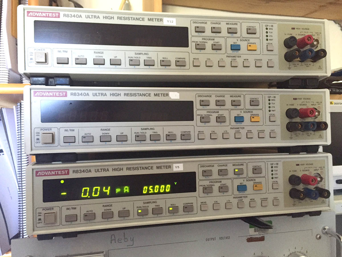
Although it is branded as an "Ultra High Resistance Meter" it is 3 equipments in one:
-voltage source/sink, up to 1000V
-Resistance meter, up to 30.000.000 Gohms
-current meter, down to 10fA of resolution.
A few specs:

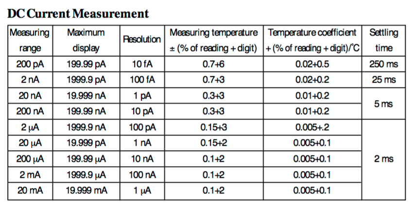

Output accuracy of the voltage source is quite good:

Both the measurement unit and the voltage source are fiber optic isolated and this allow to float the inputs up to 1100V. The input jacks can be configured to work in different configurations,explained in the manual, with or without the voltage source. Input connector is triax:

To be continued....
At the back of the unit there is the gpib, D/A output, BCD output of the data and trigger signal,

Unfortunately this ones are configured for 110VAC so I'm currently using a stepdown transformer. On the inside there are configuration jumpers but I still haven't had time to figure out how to set it for 230:

The inside is populated with 3 boards a linear power supply and a aluminum shield. Inside there is still another metal cover for the input I-V amplifier:


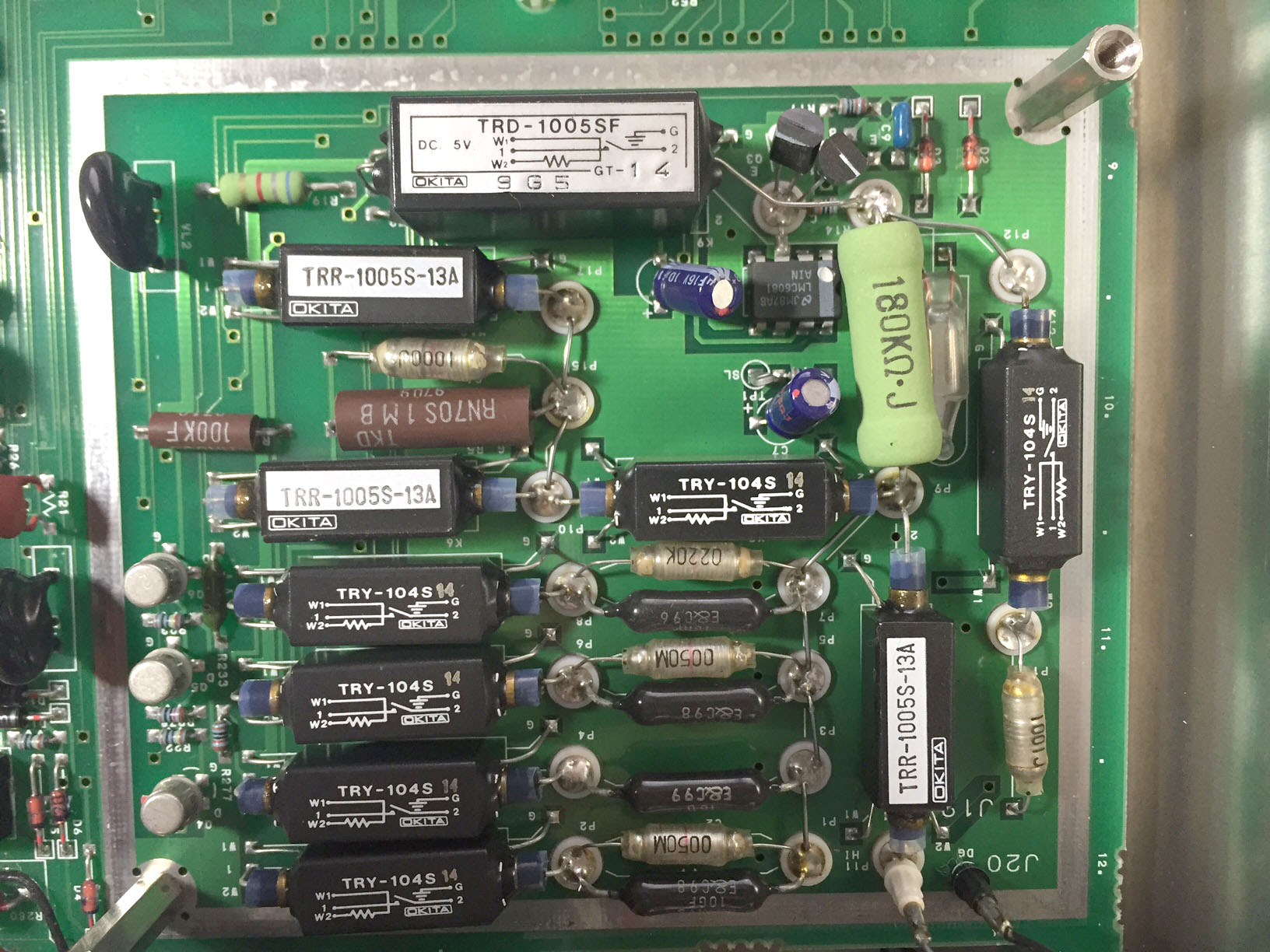
An LMC6081 , Ibias of 10fA, can be seen in the beautifully constructed IV converter. It has a ink white dot over it, so maybe it is a selected part. This is the topology according to the manual:

A 12bit DAC can also be seen next to precision resistors:

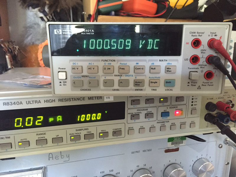
Depending on your own interests this unit may be useful or not, but I'm usually interested in measuring leakage currents of certain devices and thats why I bough these units. For example this is the current flowing across a 550V TVS when 100V is applied:

Measurement of a 100G resistor:

Thanks for tearing it down, I always liked seeing the internals of Advantest gear.
The gain of the I-V transimpedance amp can make a difference on the measure and it needs to be adjusted according to ones objectives. The manual gives some ideas,

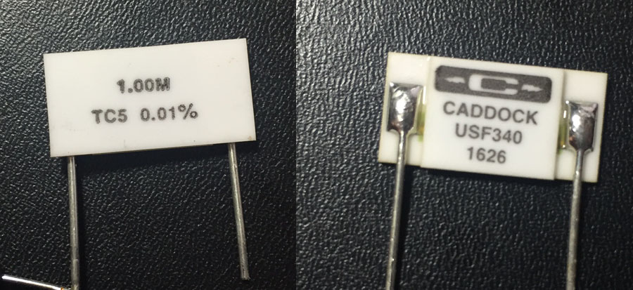
I took a 0.01% 1M resistor and applied 1V to it, with a gain of x10000 noise becomes worst but it can be offset with a higher integration time:

This unit seems to be oriented for testing in production lines. Among other features it has some programs that automate the execution of the measurement, voltage source discharge (in case there is a capacitance at the output), charge, measurement, and discharge. It has 6 programs and the times/delays are selectable. This is one of the programs:

Perfect ! Do you have some manual ? Any schematic available ?
Perfect ! Do you have some manual ? Any schematic available ?
Manual is linked in the OP... schematics I've searched but no luck
For resistance and current measurement of voltage dependent currents in at least the x1 and x10 amplifier setting modes, the 2 - 3.6 volt drop (for x1) for full scale readings will hurt the current measurement accuracy of low voltage currents. Similarly, for resistance measurement, that's why the specification sheet accuracy is for 100+ volts in the x10 and above modes.
So they are like an electrometer I guess. Are they able to source current or just voltage? My Keithley electrometer can be used to source current in the resistance ranges. You have to be careful with them because they can give you a scare-shock that can cause a nice elbow bang on the old "not so funny bone" which is always worse than the shock.
So they are like an electrometer I guess. Are they able to source current or just voltage? My Keithley electrometer can be used to source current in the resistance ranges. You have to be careful with them because they can give you a scare-shock that can cause a nice elbow bang on the old "not so funny bone" which is always worse than the shock.
This one sources voltage. I'd wish it had a function for sweeps but that could be done with gpib. Pretty happy with this instrument, before it I had no way to explore >100Mohm resistors and the sub micro-amp world.
Hi. Does it look like it is possible to change the line voltage of the meter in a simple way?
Yep, I already changed them
Not that easy. See the picture I uploaded as “voltage slection”? there are a set of wire jumpers, the space is tight and not easy to change them. If you are interested I can upload a picture of the new configuration for 240
Yep, I already changed them. check the photo below.

Just picked up one of these meters broken for pretty cheap, trying to get it running and wondering if another user had a copy of the digital board's program ROM. The display started garbled and the voltage was set to its lowest (putting 14V on the input of the LM317 powering the 5V rail!) I swapped the jumpers to be 120V friendlier (only 11V now, that handwritten note was quite useful!), then swapped the socketed 74ALS245 for a replacement an HCT, but operating frequency is only 2MHz) because I was seeing runt pulses on the RAM data lines. Still seeing the runt pulses, but now the front panel reads Err LR on boot - which is a logic ROM fault.
If anyone has an R8340A with a good ROM they can copy, I would be very much appreciated. The handwitten code on the window cover for the UV EPROM reads "002672 B01".
I can do that no problem, will do it this weekend. The lack of schematics in this meter is really frustrating. I had a couple with weird things displayed and I'm sure its an easy repair from the logic side but with no schematics...
That would be very appreciated! I've got a programmer and a couple SST27SF512 on the way as a replacement - hoping I can go with a newer flash based EEPROM replacement instead of the older UV stuff, and the pinout and configuration seem to match. Since the chip can still get runt pulses out, so long as the programmer is high enough impedance and is driven fairly slow, I may actually be able to salvage the data on the ROM, but even if I can extract it, there's no guarantee it will be good and I haven't used the programmer that's on its way.
It seems basically all Advantest gear is very closed... and the little technical servicing information available is often in Japanese. Makes it difficult, but stuff is generally well laid out and labeled, but sometimes it's very tightly packed together. The RF gear in particular I tend to pull off the chassis cover and just find a whole new chassis worth of plates holding in and shielding various assemblies, can take quite a while to figure out how to even disassemble. This instrument and its little brother, the R8240 seem to be very tough to find info on outside of some catalogs that don't even list them as made by Advantest.
I've only looked in depth at the logic board under the BCD output board, but aside from one chip, it's not too bad to get an idea about. The one I couldn't find data on was the MB8873H, but from the connections and the limitations of the micro, I think it's an address expander or some kind of memory controller - data lines from the RAM and ROM at least connect to it and the MCU seems to only have 64k worth of address capability built in, even though the ROM alone is that big.
Here it is. I have version 2_53 though. But HW is probably compatible, give it a try
The ROM file shows up as 0kB and is an empty zip file when downloaded, I think something went wrong?
I've gotten the programmer and even overdriving the Vcc for the ROM I can't get the checksum to match on two consecutive reads. I made 15 copies at various settings and saved them, but I doubt any will be an uncorrupted image. The fairly inexpensive programmer I have probably doesn't support lowering the high threshold voltage low enough to catch the runt pulses consistently, but I'll experiment a bit more as I wait for the replacement chips to arrive.
The ROM file shows up as 0kB and is an empty zip file when downloaded, I think something went wrong?
reuploaded, dunno what happened
I've gotten the programmer and even overdriving the Vcc for the ROM I can't get the checksum to match on two consecutive reads. I made 15 copies at various settings and saved them, but I doubt any will be an uncorrupted image. The fairly inexpensive programmer I have probably doesn't support lowering the high threshold voltage low enough to catch the runt pulses consistently, but I'll experiment a bit more as I wait for the replacement chips to arrive.
Same thing happened to me when I was reading mines, I was using Virtualbox to run the reader program (mine is Elnec), cause all I have is macs. I switched to the same program in another computer but this time using VMware and it was fine. No idea what happened there.
I believe the R8340 has SW version 2-01 and R8340A has 2-53
 : https://www.eevblog.com/forum/testgear/keithley-64856487-teardown/msg1126821/#msg1126821
