-
Anyway what's best way to calibrate it?
I bodged a 1000 divider with a 10K ohm resistor over a 10 ohm resistor.
The divider output was connected at channel A of the scope and the not divided output of the signal generator was connected to channel B.
I than used a function generator set to 5V DC offset, 100mV sine at 1Hz and trimmed last stage opamp gain to get the 10.000 factor.
I know this is equal to a 10K ohm source ... but considering that gain at 1Hz and at 5Hz is the same, it should be enough time for the capacitor to settle.
What I must do if I'd like to test the preamp at more higher frequency? Buffer the divider output? -
Hello,
Don´t understand: a 10K to 10R divider has 10R (ok 9.99 R) impedance at the output
You can also measure the resistors with a DMM to get more accuracy than the resistor tolerance.
10 or 100 Hz is nothing where I would worry about.
The only thing you have to keep in mind is that the input resistance of the amplifier is 1K.
So with 10R impedance at the input you have 1% loss (-1dB) by the 10R to 1K voltage divider.
with best regards
Andreas
-
Amplitude calibration is one thing. In the middle range the gain is set by the resistor ratio and thus should be rather close to the nominal value. So there should be not much difference from the nominal value.
The second part to check is the filter frequencies. The noise reading (RMS) also depends on the frequency limits. Usually capacitors have much higher tolerance than resistors. So measuring the frequency response can be as important too.
It should be OK to use something like frequency generator and DSO to take the curve. One could get around the frequency calibration if the frequency band is set behind the amplifier.
If very low noise is measured, one should also know the amplifiers own noise to subtract it. So the first test should be checking the noise the amplifier itself, both with a short and open. -
OK Andreas I learn something new about divider impedance today ...
I checked -3dB and it was exactly at 10Hz as by Andreas simulation.
Noise shorted (included scope noise) is less than 100nV rms ... with open leads is a 20% more than with shorted leads.
I measured also 2 lipo cells in series and noise was just a little bit more (maybe something like 20nV) but it's hard to tell.Hello,
Don´t understand: a 10K to 10R divider has 10R (ok 9.99 R) impedance at the output
You can also measure the resistors with a DMM to get more accuracy than the resistor tolerance.
10 or 100 Hz is nothing where I would worry about.
The only thing you have to keep in mind is that the input resistance of the amplifier is 1K.
So with 10R impedance at the input you have 1% loss (-1dB) by the 10R to 1K voltage divider.
with best regards
Andreas -
If very low noise is measured, one should also know the amplifiers own noise to subtract it. So the first test should be checking the noise the amplifier itself, both with a short and open.
Hello,
unfortunately neither of both measurements is the worst case as the leakage current (under bias) of the input capacitor contributes a large amount of low frequency noise.
I recommend using a low noise battery (e.g. several AA NiMh cells) near the maximum voltage that you want to measure (e.g. 10V) as additional test.
The tolerances of the WIMA capacitors which determine the -3dB frequencies is usually well under 5%.
The 3300uF input capacitor is dimensioned in a way that -20% can be tolerated.
with best regards
Andreas
-
Anyone of you got a spare PCB to part with?
-
I have still some spare one ... send me a message with your address and I will tell you how much will be shipping. PCB is for free.
-
i have been playing around with LTspice hovering around these ULNA schematics intermittently. out of the blue, i remember J diddy P 's circuit on ESR, both sides of the probe could be floating w/o a GND. so in theory, the isolation cap will not be charging? should a differential style be more "instant" or "stable" ?? (see pic)
V1 = 2nV pp, output is nearly 14uV pp
what could i have missed in this? as it appears to be too "simple" for a ULNA?
a side track question, what kind of amplification is this normally called? a Bifet? JFET + PMOS?
-
The amplifier circuit is running without feedback at the input stage. So the amplification will not be very stable.
The critical part is only the first JFET - due to the gain of the first stage, the second stage (P-MOS) is not critical. For this application, there is no need to have differential amplification - just one side is enough. However this leads to a little more distortion - the differential version reduces distortion and DC drift, but also increases noise. However real life the matching will not be that good - so there will be some drift and distortion. -
The amplifier circuit is running without feedback at the input stage. So the amplification will not be very stable.
The critical part is only the first JFET - due to the gain of the first stage, the second stage (P-MOS) is not critical. For this application, there is no need to have differential amplification - just one side is enough. However this leads to a little more distortion - the differential version reduces distortion and DC drift, but also increases noise. However real life the matching will not be that good - so there will be some drift and distortion.i tried a feedback resistor between G-AA, i suppose that will do as a stabilizer?
it appears i am not good at this . G-AA are in phase and will not create a negative feedback
-
I have got few more LNAs stashed from pipelie

Not sure what "A" index means on 3 of the units.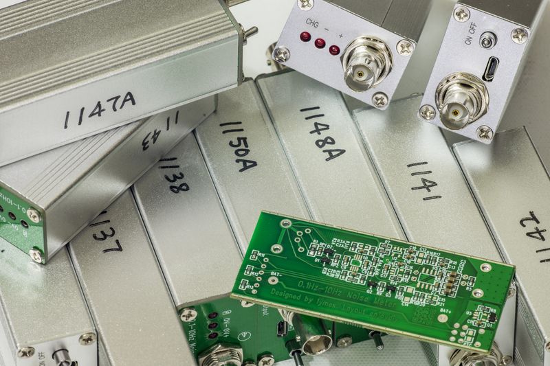
-
I have got few more LNAs stashed from pipelie
Not sure what "A" index means on 3 of the units.
Are you going to sell some perhaps?
If not, I might design and build some myself, I might even have the same enclosure (from Aliexpress). Is this the one based on this schematic by zlymex:
(with just micro USB and some USB -> 1S LiPo charger IC added?)?
Thanks! -
I have got few more LNAs stashed from pipelie
Not sure what "A" index means on 3 of the units.
Thank you!
schematic added
-
I have got few more LNAs stashed from pipelie
Not sure what "A" index means on 3 of the units.
Are you going to sell some perhaps?
I'm still have some LNAs. if you want to have it, send me a PM.
Thanks. -
How sensitive is this or any other design shown here in matters of humans hand? The 0.1-10Hz LNA design I copied by Andreas needs a cookie box with good ground connection to the scope, otherwise the amplifier is pretty sensitive to humans body. The aluminium profile case I used is not enough shielding.
-branadic- -
i have been playing around with LTspice hovering around these ULNA schematics intermittently. out of the blue, i remember J diddy P 's circuit on ESR, both sides of the probe could be floating w/o a GND. so in theory, the isolation cap will not be charging? should a differential style be more "instant" or "stable" ?? (see pic)
V1 = 2nV pp, output is nearly 14uV pp
what could i have missed in this? as it appears to be too "simple" for a ULNA?
a side track question, what kind of amplification is this normally called? a Bifet? JFET + PMOS?
Small problem - C2 is the wrong way round - C2 and C9 are supposed to eventually end up charged to 0.5 x V1, assuming identical leakage currents for C9 and C2. (Time constant = 50uF,200Kohm = 100 seconds)
But since C2 will be reverse biased the capacitor leakage currents will likely be very different and hence VC2 <> VC9.
Only one capacitor is needed anyway so it perhaps wouldn't make much difference in reality, except that the noise created by the capacitor leakage currents may be much worse, (or maybe less?) due to the reverse bias. -
How sensitive is this or any other design shown here in matters of humans hand? The 0.1-10Hz LNA design I copied by Andreas needs a cookie box with good ground connection to the scope, otherwise the amplifier is pretty sensitive to humans body. The aluminium profile case I used is not enough shielding.
-branadic-
I've not had any issues with external static or EMI fields with mine. I can pick it up and move it around without any noticeable effects. -
How sensitive is this or any other design shown here in matters of humans hand? The 0.1-10Hz LNA design I copied by Andreas needs a cookie box with good ground connection to the scope, otherwise the amplifier is pretty sensitive to humans body. The aluminium profile case I used is not enough shielding.
Hi branadic,
-branadic-
I have been through that before, when I built the 1.0 version, the trick is the 10Hz 4th order LPF, unless your scope have a digital filter work as 10Hz 4th order LPF.
-
How sensitive is this or any other design shown here in matters of humans hand? The 0.1-10Hz LNA design I copied by Andreas needs a cookie box with good ground connection to the scope, otherwise the amplifier is pretty sensitive to humans body. The aluminium profile case I used is not enough shielding.
-branadic-
I've not had any issues with external static or EMI fields with mine. I can pick it up and move it around without any noticeable effects.
the LNA Still SENSITIVE to vibration , due to the Piezoelectric effect of Ceramic capacitor I used in output stage. if you drop it or strike the case?you will see waveform on scope jumping around. -
At the very low level also the electrolytic cap can react to mechanical stress. So not sure it's the caps at the output that make it vibration sensitive.
The 10 Hz upper limit might be a good idea to get direct 0.1-10 Hz readings to compare to a data-sheet. However if used in combination with an FFT, it might be an advantage if a higher upper (and maybe lower lower) frequency limit is possible too.
Also keep in mind that with just adding an extra 2 nd order low pass behind the existing LP will lower the effective upper limit a little. It would be nice to have the calculated frequency response for the amplifier in the instructions. Giving just a frequency range for a noise measurement is tricky, as the filters are not ideal brick-wall and the type of role of can make a difference. For the lower end one might assume a 1/f type noise and thus could get an effective lower limit that works most of the time. But at 10 Hz, it depends on the noise source - the effective upper limit is different if there is dominant 1/f noise at 10 Hz or not.
With an aluminum case the contact to the case can be tricky. Sometimes aluminum does not make a good contact due to a strong oxide layer. -
At the very low level also the electrolytic cap can react to mechanical stress. So not sure it's the caps at the output that make it vibration sensitive.
The 10 Hz upper limit might be a good idea to get direct 0.1-10 Hz readings to compare to a data-sheet. However if used in combination with an FFT, it might be an advantage if a higher upper (and maybe lower lower) frequency limit is possible too.
Also keep in mind that with just adding an extra 2 nd order low pass behind the existing LP will lower the effective upper limit a little. It would be nice to have the calculated frequency response for the amplifier in the instructions. Giving just a frequency range for a noise measurement is tricky, as the filters are not ideal brick-wall and the type of role of can make a difference. For the lower end one might assume a 1/f type noise and thus could get an effective lower limit that works most of the time. But at 10 Hz, it depends on the noise source - the effective upper limit is different if there is dominant 1/f noise at 10 Hz or not.
With an aluminum case the contact to the case can be tricky. Sometimes aluminum does not make a good contact due to a strong oxide layer.
I think you are right about the electrolytic capacitor. when I built the 1.0 version which doesn't have 4 order LPF(or ceramic capacitor in the signal path), the LNA is not that sensitive to vibration compared to the later version.
I did consider building an LNA with selectable bandwidth, such as 10Hz LPF,100kHz LPF, 1MHz and wide bandwidth, Maybe this year, I hope so.
and about the aluminum case, I'm aware of the oxide layer, but I don't worry about it, the oxide layer is very thin, and there are multiple points on the case can make good contact.
here are some results about the frequency response. tested by my friend jam.
-
I finally decided to reprint my PCB of the Andreas based noise amplifier along with other PCB I made and today I completed the assembly.
@mimmus78 Thanks for the PCBs!
@Andreas Thanks for the circuit!
Just build one and here are my first results (with 3,3mF ~2nA leakage, circuit without any enclosure):
-3db @0,09/9,7Hz --> all nice
8,7V 33mF: ~200nVpp (10min) --> nice low noisefloor
0V short: ~200nVpp (10min)
--> there is essentially no relevant difference between low noise voltage source and short at input
-
Just build one and here are my first results (with 3,3mF ~2nA leakage, circuit without any enclosure):
--> there is essentially no relevant difference between low noise voltage source and short at input
Hello,
what manufacturer/type of 3,3 mF capacitor did you use (2 nA is really low: at which voltage?).
the first picture with the "artefact" in division 9+10 makes me think of some interference (perhaps with a switchmode supply).
I would put all into a metal cookies box. (I recommend "LAMBERTZ" http://www.lambertz-shop.de/composition-1605.html)
with best regards
Andreas
-
what manufacturer/type of 3,3 mF capacitor did you use (2 nA is really low: at which voltage?).
the first picture with the "artefact" in division 9+10 makes me think of some interference (perhaps with a switchmode supply).
I would put all into a metal cookies box.
The caps are Panasonic Series: M Typ: A 85°C 2000h.
Had two 3,3mF 25V for first test, one went down to ~2nA, the other to ~3,5nA @~11,5V.
They were formed @11,5V 48h + ~1week disconnected @20°C and <30%rH.
Perhaps my cheap SMPS with "high ripple" had an effect on that, for rechargeable batteries the positive effect with reflex/pulse charging is well known...
Tested with ADA4530-1 @12V as buffer for 12h with recording of voltage drop.
So the 2nA are before soldering, did not test after.
The scope was set with BW-limit to 20MHz (only option for this Rigol) and hires-mode turned on.
As it was a first test with bodged wires, I do not give a thougt on any residues or interference in the readings.
Sure it will go into metal cookie box with coax-cables and BNC-connectors and repeat the measurements
-
Midi there is slot around first stage of the amplifier. If you manage to add a shield around it and connect the shield near op-amp GND it should improve your noise.what manufacturer/type of 3,3 mF capacitor did you use (2 nA is really low: at which voltage?).
the first picture with the "artefact" in division 9+10 makes me think of some interference (perhaps with a switchmode supply).
I would put all into a metal cookies box.
The caps are Panasonic Series: M Typ: A 85°C 2000h.
Had two 3,3mF 25V for first test, one went down to ~2nA, the other to ~3,5nA @~11,5V.
They were formed @11,5V 48h + ~1week disconnected @20°C and <30%rH.
Perhaps my cheap SMPS with "high ripple" had an effect on that, for rechargeable batteries the positive effect with reflex/pulse charging is well known...
Tested with ADA4530-1 @12V as buffer for 12h with recording of voltage drop.
So the 2nA are before soldering, did not test after.
The scope was set with BW-limit to 20MHz (only option for this Rigol) and hires-mode turned on.
As it was a first test with bodged wires, I do not give a thougt on any residues or interference in the readings.
Sure it will go into metal cookie box with coax-cables and BNC-connectors and repeat the measurements
Don not connect to the general GND as I understand that shielding works better if connected directly to the 100nf caps near the op-amp.
Inviato dal mio ONEPLUS A5010 utilizzando Tapatalk
