Just wondering if anyone else has more insides on that topic?
There is this table:

F730A: DH80417B
F731A: DH80417B
F731B: DH80417B/SZA263
all (three) with the same performance in terms of t.c. and noise, which indicates that DH80417B, no matter who manufactured them (Halske&Siemens, Dickson, TI), were similar in performance.
With F732A, still using SZA263, Fluke ovenized the reference and associated components for the first time and achieved 20x better t.c. and 2x lower noise. Did ovenizing the reference prevent air drafts/thermal fluctuations, that showed up as noise in the former models?
With F732B Fluke switched to LTFLU, wich improved noise by about sqrt(4) due to 4 zeners in parallel.
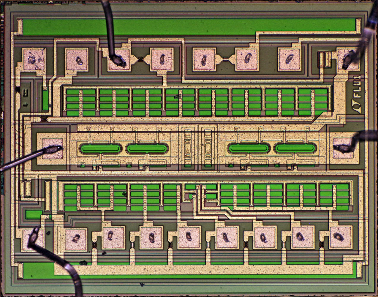
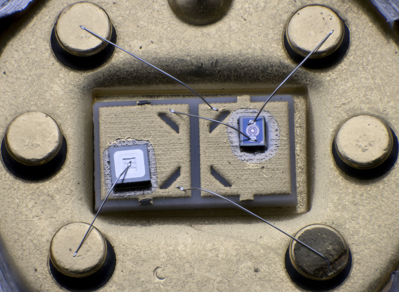
In LTFLU we can spot the two resistors on the die, that could act as heating elements, but I can't spot a temperature sensor. So question is, why would you design them in?
Are my aforementioned conclusions reasonable or is there more to it?
-branadic-
For the LTFLU one could still use the BE voltage to "measure" the temperature - no ideal, but it can be done. Depending on how good the symmetry is, the heater may not be uniform enough and possibly cause more trouble than good. An external heater can work as well.
The chip internal heater could still be used temporarily for finding the right current / number of transistors used and fuses to blow. So chances are it is used during production. Here a heater close to the reference can speed up the test and is thus very well come.
The chip internal heater could still be used temporarily for finding the right current / number of transistors used and fuses to blow. So chances are it is used during production.
Yes, it is somehow used during the production, we can see the scratch marks at the associated pads.
-branadic-
I haven't seen any LTFLU with bonded heaters. Anyway, one can use Ube of the transistor to measure LTFLU chip temperature. In 2019 i implemented that for our LTFLU reference builds. The circuit includes a 100x gain amplifier inside the oven, so there is a temperature measurement with about 210 mV/K available. The signal is used for oven tuning and for TC adjustment.
See:
https://www.eevblog.com/forum/metrology/the-ltflu-(aka-sza263)-reference-zener-diode-circuit/msg2578746/#msg2578746Later i changed the feedback network from 10K/1M to 1K/100K (metal film resistors).
Regards, Dieter
Frank also provided an answer
hereThese RefAmps all are relatively tightly specified concerning their initial reference voltage span, but especially for the span of the transistors collector current (20..200µA) where zero T.C. can be achieved, over defined operating temperature span, with zener current being 3mA.
Therefore it's clear, that they have to heat the device in situ, in turn to trim the transistor and zener to the correct above mentioned parameters.
I was more interested in how the voltage standards based on DH80417B/SZA263/LTFLU improved in spec and what was changed design-wise to get there. Anyone with more inside on that topic?
I haven't seen any LTFLU with bonded heaters. Anyway, one can use Ube of the transistor to measure LTFLU chip temperature. In 2019 i implemented that for our LTFLU reference builds. The circuit includes a 100x gain amplifier inside the oven, so there is a temperature measurement with about 210 mV/K available. The signal is used for oven tuning and for TC adjustment.
See: https://www.eevblog.com/forum/metrology/the-ltflu-(aka-sza263)-reference-zener-diode-circuit/msg2578746/#msg2578746
Later i changed the feedback network from 10K/1M to 1K/100K (metal film resistors).
I've seen your posts, but couldn't find a comprehensive report what was "finally" achieved including all the details. Unfortunately, some aspects are spread over multiple pages and threads, but others seem to be missing. Would have liked to see it all together including images of the build to enjoy the achievements made.
-branadic-
No, i posted schematics, images and some pdf-papers and hundreds of people used them. In comparison to those Fluke references my reference builds are superior as i used low temperature TEC ovens. I'd guess it's worth looking.
And yes, there isn't a final result. The last result i showed was from October 2022, where i logged the difference between two of those LTFLU builds. There were seven consecutive days where the daily averages stayed constant to 0.01 ppm. I'm pretty much convinced the ultimate LTFLU-1 performance will be about that.
Regards, Dieter
I had a Fluke 730A transfer standard Rev.B of a fellow voltnut with me for a few weeks, on which I've measured t.c. and that I'd like to share. Attached are the results.
Today I finish the t.c. measurement on my Fluke 730A transfer standard Rev.A, before I switch to Fluke 730A transfer standard Rev.B as well.
-branadic-
Interesting how ref 2 and 4 are different. Ref 2 with the hysteresis and ref 4 with the much higher TC. Ref 1 and 3 look better than I expected.
I have the impression that the Mica card wirewound resistors with the coating applied don't necessarily like rising temperature slopes from cold to warm and experience some sort of stress or wire-movement that leads to the observed hysteresis. I can see a similar effect on the Fluke 730A Rev.A reference boards (see attachement). Surprisingly, one unit shows rather low noise (green trace) compared to the others and one shows a rather low t.c. (cyan trace), besides a large hysteresis effect at the rising temperature slope from 10 °C to 23 °C.
-branadic-
I today received a very first sample of a copycat of the xformer that is used in F730A. Why I had it made? Because it allows for 4 floating references like in F730A, while primary and each secondary is shielded individually. The primary is 2x 115 V and the secondaries are 24.8 Vac with no load. I'm planning a group order so in case you are interested, please send me a message via mail or PN. More details are about to come.
-branadic-