-
Keithley 2001 DVM factory modifications to work with a K1801 nanovolt preamp
Posted by chuckb on 02 Oct, 2015 00:08 -
Does anyone know what Keithley does to modify a K2001 or a K2002 to allow it to work with a Keithley 1801 nanovolt preamp? There is a factory mod that needs to be performed when these meters are used with a K1801 preamp.
I recently purchased a K1801 preamp on Ebay. The interconnect cable and the power supply card were not available from the seller or Keithley. The K1801 manual has a schematic so I am using that to lay out a pcb and build a the k1801 power supply card to get this all working. Should be a fun exercise.
Thanks -
I believe you can enable it through the secret menu options. Similar to adding the extra memory. I am pretty sure I seen it in there.
-
I can verify the preamp option appears and gives the option to enable it in the secret menu on my 2001.
-
So it was you, who snagged it. Eh, I was not quick enough to bid more

Please, please, do post inner photo and better external photos of preamp. Few voltnut's here already commited to making DIY preamp board for K2001/2002's we have here.
/!\ Do not remove short from preamp input terminals to avoid ESD damage!
To get it all working, you need:
* Make own preamp supply board (which goes into option slot in DMM) with very quiet isolated PSU, I2C EEPROM to store preamp cal/gain data
* Make cable to interconnect preamp with your preamp board
* Ensure your meter have B-firmware.
* Plug preamp addon board into meter, initialize preamp's EEPROM by using secret menu, article here.
2001 have to have B-firmware, not A-firmware, as only B-firmware supports preamp functions. Model 2002 A-firmware is OK for preamp.
There are no modify to multimeters itself.
I'm ready to provide all support you need for this project, just keep it up, as it's pure rare animal.
If you feel complexity of doing all this is over the top - let us know, I'm sure we could do this project together. -
Hi chuckb,
Welcome in the best forum for the Keithley 2001/2002 DMM!
I am hunting that K1801 since the 18th March 2015:
https://www.eevblog.com/forum/testgear/restoration-glory-of-keithley-2001-dmm/msg632100/#msg632100
unfortunately with no luck. Now your message give me a big hope. I am so excited you have that baby now.
Please open it up very carefully and make tons of pictures...
Very interesting project indeed!
PS: How much was your bid in Ebay? 1100$?
-
Wow! Thanks for all the info and support. Thanks for the info on the firmware. That's what I was looking for.
I already have two of the EM Electronics A10 preamps. One is from Ebay and I have not checked it out yet. The other one is powered from some NiCad batteries, solar cells and a 100 watt flood light. That should keep the leakage currents low! I really should update that to LED illumination some day. I'll send some data files of the zero noise if you would like.
I believe I paid $600 for the A10 preamp when I ordered it from England 15 years ago. You might check the price of the A20 preamp. It has digitally selectable gains so we could probably make it work with the K1801 power supply card that I'm building. (The A20 may be a K1801 preamp in a different package)
I also have an old (1970s) N2a nanovoltmeter from EM Electronics. It needs a little work but I don't have any info on circuit details. I should probably start by changing the PS caps. Get those nasty electrolytics out of there.
I believe these are all modern versions of the K148 nanovoltmeter. Reference the Keithley web site for the schematic. The K148 uses a mechanical chopper to turn the DC signal into an AC signal to feed to the step up transformer (1:100 ratio?). Then you can use normal electronics to amplify the signal and demodulate it. The transformer lets the input noise be 100 times less than the first stage amplifier noise. Nothing is free so the trade off is 100 time higher input current. But in most low noise applications that is not an issue. The newer versions probably use low resistance MOSFET transistors to do the switching.
I saw a very good design article for a chopper transformer nv preamp in The Review of Scientific Instruments back in the 90s. I'll try and find it. I had to go to the local college to look it up.
Does anyone have a download of the Calibration EEPROM on the K1801 preamp card? I think the meter will probably need SOMETHING loaded in memory before it will let me do a calibration. I don't know though.
Yesterday I ordered the two little transformers for the K1801 power supply PCB from Tektronix. Together they cost as much as the preamp! I did not want to spend the time to design new ones. I'll have to do a little reverse engineering after they come in so the next person does not have to pay that...
The last part I need to identify is the connector that goes into the K1801 preamp. It looks like a wide Ethernet connector. I'll get some pictures and more details over the week end. After I get the PCB laid out I'll let you guys know. Hopefully it will be done by the end of the year. If anyone wants a PCB blank I can order extras at that time or anytime.
I'll see about pictures this weekend. I don't know how far down I can disassemble it. You have to be careful with Mu Metal shields. If you stress (drop) it it can change it's annealing and shielding properties.
All my low noise projects have been on hold for the last few years while I built a new workshop. I should be able to move into it by the end of the year. This hobby gets expensive!
Again, thanks for the support, I'm sure I'll need it. -
Happy to have you onboard.
What are you using all that nano-stuff for, if not a secret? You look serious into low-signal measurements.
I don't think need anything in EEPROM that goes in preamp card, as secret menu item initialize all data for you. Then after you calibrate it with usual meter's menu for preamp, it will write settings like gain and offsets into EEPROM.
That's what it does in secret menu for NVRAM option anyway, so I don't see why should be different.
If you can shred more light and photos on details, specially about Tektronix transformers parameters, that would be great help. All rest parts seem to be common.
I can make PCBs for you if that is needed.
As of connector, perhaps it's RJ50 or other RJ-type? There are 10p10c and 15p15c types on market, like here at Digikey, perhaps similar? I don't have any details , since best photo I saw is the one ebay pic of yours unit.
I've got Keithley 182-M, on which I did review just few weeks ago, so would be interesting to compare performance of both. -
The Keithley 1801 is an EM Electronics A10 made to order for Keithley. traded some emails with EM recently.
It will be interesting to see your results!
-
I pulled the covers from both preamps and took some pictures. While I had it open I did a little circuit tracing to figure out the connector pin out.
I hope these attachments come through.
Does anyone have the specs on a Teledyne 9491BJ Zener? It's in what looks like a power supply monitor circuit.
The back of the K1801 pcb has 'A10 K" printed on it. So yes it looks like a version of the A10 preamp became the K1801 preamp. As you can see there are two selectable filter caps and 3 gain setting resistors.
We are off to watch "The Martian".
-
Quote
We are off to watch "The Martian".
Enjoy
That's a good start.
You can upload fullsize photos to ftp.xdevs.com with logic doc and password docsite. No size of file type limits
I wonder what's inside the can.
Also if you can take PCB bottom side - would be great, as K1801's PCB is single-sided!
-
chuckb
Thanks so much for the pictures! it is so interesting to have a look inside your K1801. I sign up for a board, it is a very interesting project!
take care,
Z -
Transformer update.
The K1801 power supply card has two transformers. I ordered them from Tektronix and they arrived in under a week. They are not cheap.
These are both Ferrite POT style transformers in 18 mm x 11 mm packages. The bobbin foot print is given in the attached pdf.
TR-285B ($193), core material 3E2A.
Primary, wire dia 0.0315" with insulation, this may be 20 ga. DC resistance = 0.0033 ohms. This is 3.9 inches of 20 ga wire.
Secondary, wire diameter 0.004" over insulation (difficult to measure), this may be 38 ga wire. The secondary winding is center tapped so there are two identical windings. DC resistance for one of the two matched secondary windings is 10 ohms. This is 15.4 feet of 38 ga wire.
When 0.1V RMS at 4.8 kHz is applied to the primary, half of the secondary generates 11.2V RMS.
TR-286B ($393), core material 3E27.
Primary wire dia 0.004" over the insulation (difficult to measure), this may be 38 ga wire. The primary is center tapped. The DC resistance of each half of the primary is 1.55 ohms.
This would be 28.7 inches of 38 ga wire.
Secondary #1 winding. This wire is smaller than the primary. I measured 0.003", again, this is very difficult to measure. I broke one of the wires trying to measure it. It may be 40 ga. This output is center tapped. The DC resistance of half of the winding is 12.6 ohms. This would be 11.7 ft of 40 ga wire.
Secondary #2 winding. This stranded wire is 0.028" in diameter (22 ga?). The wire is insulated as it goes into the transformer. The insulated wire is 0.047" in diameter. It has a DC resistance of 0.0061 ohms. This would be 4.5 inches of 22 ga wire.
With 2 V RMS applied to half of the primary, half of Secondary #1 developed 3.4 V RMS. Secondary #2 developed 0.0715 V RMS.
The TR-286 Secondary #2 feeds the primary of the TR-285 transformer. This looks like a technique to reduce leakage currents to the preamp. Insulated wire is used to reduce capacitive coupling inside the transformer and a low voltage excitation AC of less than 200mv is used to reduce capacitive coupling some more.
Before anybody asks, no I do not plan to take the cores apart and actually count the turns of wire. I can't count that high... The core material was the big unknown for me. The transformer winding details can be determined through experimentation.
All resistance and voltage reading have been double checked but I may still have made a mistake. All wire gauges are my best guess.
I got distracted this week when my K2002 showed up. It was calibrated in Aug of this year!. All the resistances measurements above were performed with the K2002 using 4 wire leads, offset comp was turned off. The inductance of the transformers may have disturbed the offset comp operation. I checked the K2002 against my 1 ohm Thomson standard before testing. The meter has the A10 firmware and I will upload that as soon as my ROM reader arrives. All the chips have 2009 dates codes so it's a pretty new meter. I will be doing the MEM2 mod as soon as my next package shows up from Digikey.
-
Great, I'll make a preamp PCB then for attached footprints, following k1801 schematics, more or less.
Great to hear about your 2002. You officially have best and newest Keithley out here Looking forward for firmware.
You can dump cal data too just in case, it is in little 24C16s. It's little unconvinient, as there are two EEPROMs so I used Raspberry Pi with isolated I2C via ADUM2250 to read both chips while meter powered on and kept in RESET (test point tied to GND). I can post more details later, since my 3458A repair is on hold, waiting more xpensive parts .
.
Connector measurement: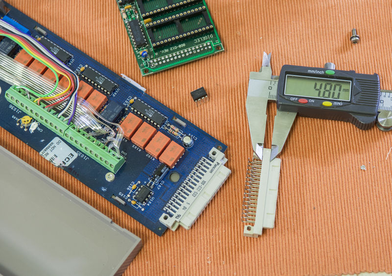
-
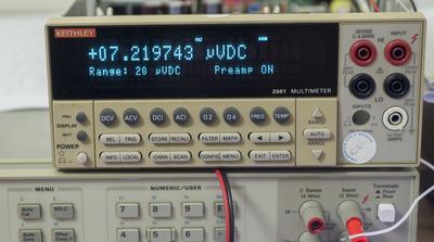
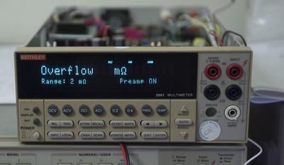
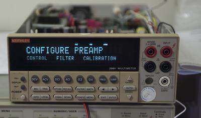
Testing I2C EEPROM with PREAMP config on addon port with K2001 B17:
-
I fired up an old A10 preamp to understand what it's noise floor is. This preamp is powered by two 12v, 1.2 AH Lead Acid batteries. Each battery feeds an LT1021-10 very low noise precision voltage reference. The outputs of the two independent regulators power the A10 preamp.
I have the A10 input shorted and the gain set to 1,000,000. So the 5nv of offset becomes 5mv. That is supplied to a K2000 for digitizing. The attached photos and plots show the noise performance over 4000 seconds, a little over an hour.
The bench temperature is measured and recorded to 0.001 deg C with an HP2804A Quartz Thermometer. Normal quartz crystals are cut to minimize frequency change with temperature. This quartz sensor is cut for a linear frequency change with temperature. There may be several degree C temperature variation around the bench but this information is supplied as a reference.
The raw (1 second sample) noise was averaged over 60 samples and displayed on the same graph. This shows the 1 minute average of noise was within 1 nVpp for over 30 minutes. That's pretty good.
I'm looking forward to comparing it to the K1801 preamp. Maybe I'll power it up with the batteries and see what happens.
-
chuckb Are you a E/E hobbist? That's a real good set up. Maybe I am missing the two VSupply to the A10 in the graph. I am sure the LT1021-10 has a very low drift, but it would be interesting to see if the drift in the A10 is correlated to the VSupply.
-
I has a similar setup with Keithley 2100 and EM Electronics N1a as preamp. Noise floor was 2 nV p-p without any filtering or averaging (time constant 0.25 sec). 300 pV p-p with a max filter setting (TC=40 sec).
-
I have collected a lot of nV equipment from ebay over the years. My day job is an EE at an aerospace company. My hobby is precision electronics. The day job does not have enough precision electronics work to satisfy me.
For voltage I have several nV preamps and several 7.5 digit and now an 8.5 digit DVM.
For frequency I have GPS stabilized Rb Frequency standards for 12 digits of stability. I got an HP 5370B frequency counter (12 digits, 20ps) for a good price from ebay a few years ago.
I shut down the air conditioner last night and ran the A10 preamp for 5 hours. Attached is the plot.
-
Thanks chuckb, we need people like you here! I am so glad you joined us.
-
zucca - Thanks for the welcome. There are not many people interested in this corner of the electronics world.
I did a little test this evening. There was a few nv shift in the A10 when I took the battery off of charge. The output of the LT1021-10 dropped 100uv when I took the battery off of charge. The gives my implementation of the A10 a power supply rejection ratio of over 90dB. It may be in the preamp and it may be in my wiring. Life is not easy in the nV world.
Micke T - Great performance from the N1a. I have an N2a but I have not had a chance to test it out yet. There is a connection for batteries but no batteries are installed. I have no manuals for this unit. One battery connector has 20v on it and the other has 6v. Any ideas on what type of battery it needs?
-
Connector measurement:
If you are looking for that connector, you can try these - the original Pancon one has been discontinued.
http://uk.farnell.com/harting/09-27-232-6801/socket-din41612-q-2-32way/dp/1313796?ost=1313796
http://uk.rs-online.com/web/p/din-41612-connectors/7706950/
I can vouch for the first one, as I'm using it in a home-made scanner card and it fits the counterpart fine, though it doesn't have the alignment notches. -
chuckb - I have a N1a Service Manual from Ernest J. Moorey, but can't find any information about batteries. The measured voltage is 9-10 V.
-
z01z, thanks for the part numbers. Digikey also has the Harting. About $10USD ea.
-
z01z, thanks for the part numbers. Digikey also has the Harting. About $10USD ea.
This Hirose is 4.13
-
Hirose must not be as proud of their connectors as Harting.