-
two LTZ1000 in "series" and attenuate to 10V?
Posted by
aronake
on 28 Mar, 2024 13:16
-
Hi,
The usual LTZ1000 10V design is to have one LTZ1000 and amplify output signal to 10V.
I am thinking of making a design with two LTZ1000 in series to get around 14V, then attenuate that down to 10V with OP amp and resistors.
My thinking is that there then would be noise from two LTZ1000 would be a bit higher than from one, but then the attenuation largely scale down the noise linearly with attenuation.
Theoretically would the noise be less than the regular multiple LTZ1000 design which seems to be to average output then scale up to 10V?
Has anyone tried a design like this?
Thoughts?
-
-
"Theoretically" the relative to the full scale random noise will go down when using multiple zeners in parallel or in series in exactly the same proportion of the square root to the devices number. So if you have 2 devices output summed in parallel or in series the noise will be lower by 3dB (1.41 times). Unfortunately the LTZ1000 is rather more difficult to arrange in series if you plan to use the internal heater and temperature control, so a parallel connection makes more sense. The LM399 on the other hand, with 3 in series for ~20V, and than divided by 2, could be an interesting arrangement... .
Cheers
Alex
-
#2 Reply
Posted by
tszaboo
on 28 Mar, 2024 14:06
-
You can also put 72 in series and divide it down with a 1:100 divider!
The reason they don't do it is simple. It's not "just a zener" it has a heating circuit, where the current has to go somewhere, and the top heater current would need to go through the bottom zener. Or you isolate the circuit, which opens up a lot of other issues about noise. Oh, and because it costs like 40 EUR per IC.
-
#3 Reply
Posted by
dietert1
on 28 Mar, 2024 20:59
-
..
Has anyone tried a design like this?
Thoughts?
I am using a double LTZ1000 reference for my DIY voltmeters. Supply voltage is 18 V, reference output voltage is 14.xx V. The two heater circuits are in series, so each one can get up to 9 V. The lower one has the notorious diode in the heater circuit in order to avoid substrate currents. And the 9 V is the output of an opamp that provides/absorbs the heater current difference. The circuit worked well from the very beginning. The board runs inside an outer oven, so one can use the LTZ heaters at rather low power. See thread about "Prema BK7 derived multimeter".
Noise will be about 30 % lower, similar to a double zener array (1/sqrt(2)).
Regards, Dieter
-
#4 Reply
Posted by
Kleinstein
on 28 Mar, 2024 21:09
-
Noise wise and for the sensitivty to the resistors there is not much difference between the 2 paths ( 2 in series and 14 ot 10 V or average from 2 and than 7 to 10). The step from 7 to 10 is rather similar to the step from 14 to 10, just the other direction. It could be a little easier to start with 14 V and go down, if a PWM type divider / DAC is used and not resistors.
Haveing 2 x LTZ1000 in series is extra effort and complications. Having 2 x Ref in parallel makes it possible to measure the difference of the references as an added self test and there is also the option to use only 1 reference with little change or as a first start.
-
#5 Reply
Posted by
KT88
on 29 Mar, 2024 00:35
-
Summing two references in series should have the same effect as paralleling them - noisewise...
As the other comments hint - it comes with some complexity and pitfalls.
A slight advantage could be expected from the input referred noise of the Opamps not being amplified but attenuated - given an ingenious circuit could leverage that advantage.
However, the gain in performance would be disappointing as the Vz remains the major source of noise and in sum the reduction of noise in comparison to paralleling them would be negligible. (rule of thumb: a source with 1/3 of the aplitude of the main source only contributes 1/10 to the overall noise).
The seebeck related errors might still sum up...
-
#6 Reply
Posted by
dietert1
on 29 Mar, 2024 11:09
-
If somebody makes an array with more parallel zeners in order to suppress zener noise, they will be approaching a situation where the amplifier deficiencies matter more.
Those 4x references like Fluke 734 or that Wavetek 7004N currently for sale at ebay for US$ 20 490 support averaging (parallel array mode). Don't know whether they can be used to generate 40 V. I remember in professional analog audio they used differential high level signals of up to +/-15 V, about a factor 100 more than the usual consumer audio.
Ideally a 4x reference should support 10 V, 20 V (2 x 2) and 40 V array modes.
Regards, Dieter
-
#7 Reply
Posted by
alm
on 29 Mar, 2024 11:35
-
If somebody makes an array with more parallel zeners in order to suppress zener noise, they will be approaching a situation where the amplifier deficiencies matter more.
Those 4x references like Fluke 734 or that Wavetek 7004N currently for sale at ebay for US$ 20 490 support averaging (parallel array mode).
I'm pretty sure the Fluke 734 is just a mechanical enclosure with the only electrical connection being mains power. But the Wavetek/Fluke 7004N and Datron 4910 can indeed do averaging using resistors (the Datron 4910 also provides a buffered average output). I believe the Wavetek/Fluke 7010N can even average 10 cells. But they average after amplification to 10V. So the op-amps are also in parallel.
Ideally a 4x reference should support 10 V, 20 V (2 x 2) and 40 V array modes.
The old
Fluke 730A quad voltage standard from the early seventies had buttons to put up to four cells in parallel or series. I'm not aware of any later standards supporting this, although nothing prevents you from making those connections yourself.
-
#8 Reply
Posted by
branadic
on 29 Mar, 2024 11:37
-
In theory Wavetek/Fluke 7004 should support 10, 20, 30 and 40 V as all references are floating, similar to F730A, where you can choose between average (parallel) or series connection.
-branadic-
-
#9 Reply
Posted by
Arhigos
on 30 Mar, 2024 11:33
-
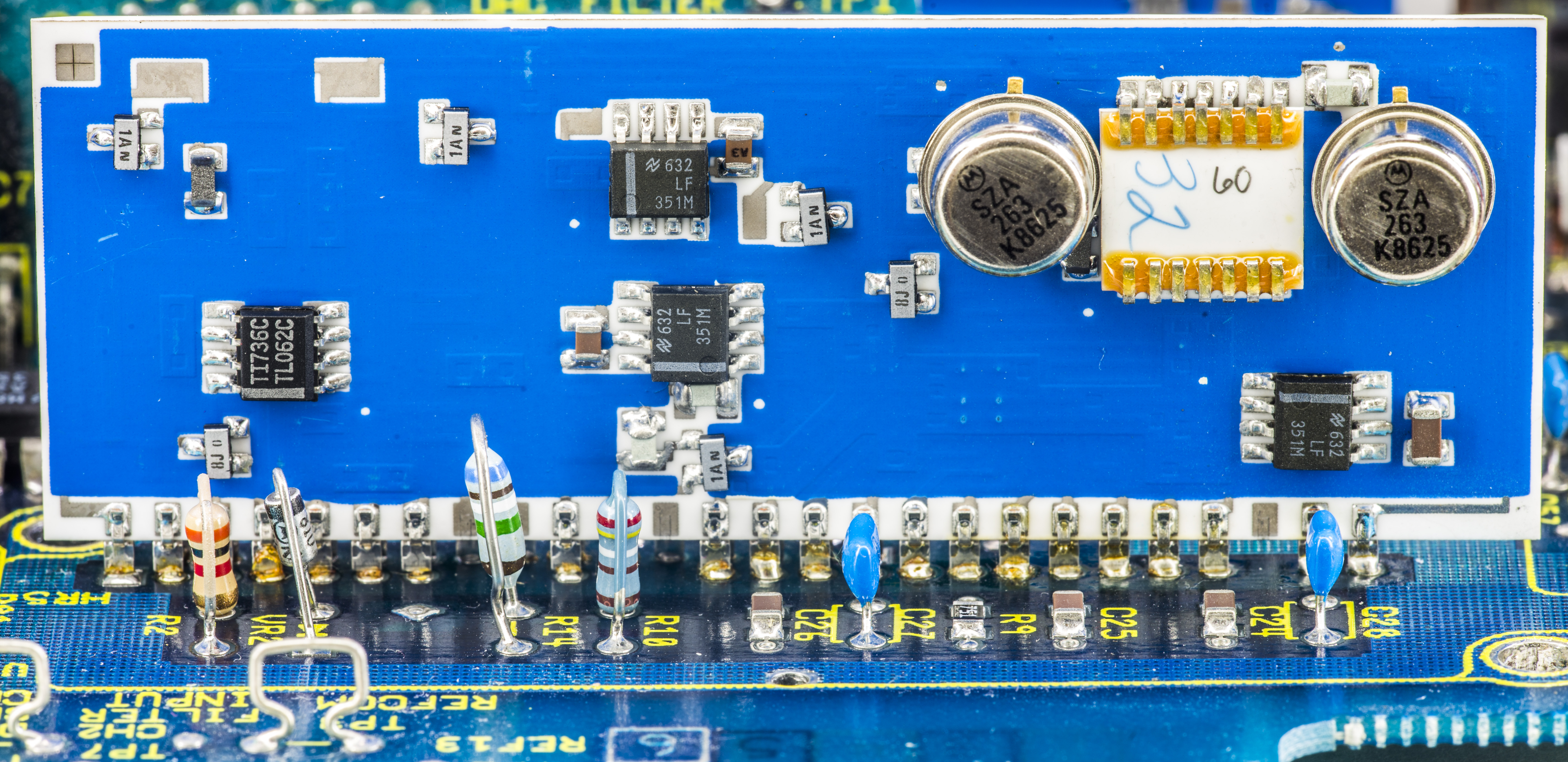
I know that fluke 57xx series are using two LTFLU(aka SZA263) chips.
But I have no idea why there s two of them

-
#10 Reply
Posted by
dietert1
on 30 Mar, 2024 12:12
-
When i made a LM399 10 V reference with time division (PWM) for the 10 to 7 V divider, i had some difficulties, since the PWM low pass filter was in the 10 V regulation loop. I got the loop stable after some iterations, but the next version had a 2x5 LM399 array with 14 V output. Then there is no regulation loop. It's just the PWM division.
Regards, Dieter
-
#11 Reply
Posted by
Dr. Frank
on 30 Mar, 2024 19:20
-
I know that fluke 57xx series are using two LTFLU(aka SZA263) chips.
But I have no idea why there s two of them
Hi, that's also used already in the Fluke 5440/5442.
From these 13V reference you can easily use a PWM, instead of first amplifying from 6.9V to 11V
the 5440 and 57x0 use ranges of 11, 22, 275 and 1100V, I.e. need D/A outputs of 0 .. 11V in each range.
That gives more stability and a less noisy reference voltage.
Frank
-
#12 Reply
Posted by
Andreas
on 31 Mar, 2024 06:04
-
Hello,
and I am pretty shure they used two with a slightly different zero TC temperature
to spread the zero TC temperature over a wider temperature range.
with best regards
Andreas
-
#13 Reply
Posted by
Mickle T.
on 31 Mar, 2024 06:16
-
AFAIR, the highest voltage reference voltage source is used in the Datron 4000A calibrator, in which two chains of 4 zener diodes (and a resistor divider) provide an output voltage of 20.5 V for a 0+-20 V hybrid PWM DAC. But it is also inferior to 8-1/2-digit voltmeter-calibrator Impulse V2-41/1, where 4 zener diodes form a voltage of 25.6 V for a multiphase PWM DAC.
-
#14 Reply
Posted by
KT88
on 31 Mar, 2024 21:09
-
I would think that possible advantages from putting heated zeners in series, probably won‘t justify the effort. Unheated ones would be a different story… It would require only one control circuit and the seebeck effect could be mitigated far more easily as the temperature gradients would be lower compared to heated ones.
A higher reference voltage in a system like a calibrator would help to reduce interferences if the reference voltage has to be distributed to multiple subsystems.
-
#15 Reply
Posted by
branadic
on 31 Mar, 2024 21:18
-
It is at least sort of easy with LMx99 and hence with ADR1399 too.
-branadic-
-
#16 Reply
Posted by
KT88
on 31 Mar, 2024 22:13
-
Neat circuit. I agree that this is easy to implement. It should work up to 4 in series….
The reason for that is the integrated heater control and the straight zener…
The LTZ/ADR1000 would need individual heater circuits. The rest of the circuit won‘t be straight forward as well…